


48FK,JK034-074 50FK,FY,JK,JY034-104 Variable-Air Volume Rooftop Units
Controls Operation,
and Troubleshooting
CONTENTS
Page
SAFETY CONSIDERATIONS . . . . . . . . . . . . . . . . . . . . . 2
GENERAL . . . . . . . . . . . . . . . . . . . . . . . . . . . . . . . . . . . 2-13
Rooftop Information . . . . . . . . . . . . . . . . . . . . . . . . . . . . 2
VAV Control System . . . . . . . . . . . . . . . . . . . . . . . . . . . 2
Processor Board . . . . . . . . . . . . . . . . . . . . . . . . . . . . . . 2
·P1 Ð SUPPLY-AIR SET POINT
·P2 Ð ECONOMIZER POSITION
·P3 Ð RESET LIMIT
·P4 Ð DEMAND LIMIT
·P5 Ð ECONOMIZER MINIMUM POSITION
·P6 Ð WARM-UP SET POINT
·P7 Ð SASP RESET TEMPERATURE
·PROCESSOR BOARD OUTPUTS
·CONFIGURATION HEADER AND DIP SWITCH
ASSEMBLY
Relay Board . . . . . . . . . . . . . . . . . . . . . . . . . . . . . . . . . . 5
Display Board . . . . . . . . . . . . . . . . . . . . . . . . . . . . . . . . . 5
Thermistors . . . . . . . . . . . . . . . . . . . . . . . . . . . . . . . . . . . 5
·T1 Ð SUPPLY-AIR TEMPERATURE THERMISTOR
·T2 Ð RETURN-AIR TEMPERATURE THERMISTOR
·T3 Ð SATURATED CONDENSING TEMPERATURE, CIRCUIT 1
·T4 Ð SATURATED CONDENSING TEMPERATURE, CIRCUIT 2
·T10 Ð RESET TEMPERATURE
Compressor Operation . . . . . . . . . . . . . . . . . . . . . . . . . 7
· CONTROL RELAY (CR)
Accessory Board . . . . . . . . . . . . . . . . . . . . . . . . . . . . . . 7
·P3 Ð RESET LIMIT
·P5 Ð ECONOMIZER MINIMUM POSITION
·P6 Ð MORNING WARM-UP TEMPERATURE
Single-Step Demand Unit . . . . . . . . . . . . . . . . . . . . . . . 7
Demand Limit Control Module (DLCM) . . . . . . . . . . . . 7
Economizer . . . . . . . . . . . . . . . . . . . . . . . . . . . . . . . . . . 10
·ENTHALPY CONTROL
·DIFFERENTIAL ENTHALPY
Variable Frequency Drive (VFD) . . . . . . . . . . . . . . . . . 12
Temperature Reset . . . . . . . . . . . . . . . . . . . . . . . . . . . . 12
CONTROLS INSTALLATION . . . . . . . . . . . . . . . . . . . 13-25
Control Wiring . . . . . . . . . . . . . . . . . . . . . . . . . . . . . . . 13
·NIGHT SETBACK THERMOSTAT
·SPACE TEMPERATURE RESET ACCESSORY
(50DJ900021)
Space Temperature Reset . . . . . . . . . . . . . . . . . . . . . . 13
·INSTALLATION
·CONFIGURATION
·OPERATING SEQUENCE
Demand Limit . . . . . . . . . . . . . . . . . . . . . . . . . . . . . . . . 18
·SINGLE-STEP DEMAND LIMIT
·TWO-STEP DEMAND LIMIT
·INSTALLATION
·CONFIGURATION
·OPERATING SEQUENCE
Control From Remote Building Management
System (BMS) . . . . . . . . . . . . . . . . . . . . . . . . . . . . . . 19
· OCCUPIED/UNOCCUPIED
Page
·NIGHT SETBACK CONTROL
·UNIT SUPPLY AIR SET POINT ADJUSTMENT
·DEMAND UNIT (1-STAGE OR 2-STAGE)
·SUPPLY DUCT PRESSURE SET POINT ADJUSTMENT
·EXTERNAL ALARM SIGNAL
·REMOTE ECONOMIZER CONTROL
Smoke Control Modes . . . . . . . . . . . . . . . . . . . . . . . . . 21
·FIRE SHUTDOWN MODE
·PRESSURIZATION MODE
·EVACUATION MODE
·SMOKE PURGE MODE
·INSTALLATION
·CONFIGURATION
·OPERATING SEQUENCE
Air Pressure Tubing . . . . . . . . . . . . . . . . . . . . . . . . . . . 23
·INLET GUIDE VANES
·VARIABLE FREQUENCY DRIVE
·MODULATING POWER EXHAUST
START-UP . . . . . . . . . . . . . . . . . . . . . . . . . . . . . . . . . 25-30 Initial Check . . . . . . . . . . . . . . . . . . . . . . . . . . . . . . . . . 25 Con®guration Header . . . . . . . . . . . . . . . . . . . . . . . . . 26 DIP Switches . . . . . . . . . . . . . . . . . . . . . . . . . . . . . . . . . 26 Adjusting Set Points . . . . . . . . . . . . . . . . . . . . . . . . . . 27 Potentiometers . . . . . . . . . . . . . . . . . . . . . . . . . . . . . . . 27
Supply Fan Control with IGV Option . . . . . . . . . . . . . 28 Supply Fan Control with VFD Option . . . . . . . . . . . . 28
Modulating Power Exhaust
(Option or Accessory) . . . . . . . . . . . . . . . . . . . . . . . 30
START UNIT . . . . . . . . . . . . . . . . . . . . . . . . . . . . . . . . 31-34
Quick Test Program . . . . . . . . . . . . . . . . . . . . . . . . . . . 31
OPERATING INFORMATION . . . . . . . . . . . . . . . . . . . 34-43
Digital Display . . . . . . . . . . . . . . . . . . . . . . . . . . . . . . . 34
·CODES 0 THROUGH 8, CAPACITY STEPS
·CODES 20 THROUGH 30 AND 88, OPERATIONAL STATUS
·CODES 51 THROUGH 87, DIAGNOSTIC
INFORMATION
Operating Sequence . . . . . . . . . . . . . . . . . . . . . . . . . . 35
·SIZE 034, 038 AND 048-088 UNITS
·SIZE 044 UNITS
·SIZE 104 UNITS
Head Pressure Control . . . . . . . . . . . . . . . . . . . . . . . . 36
Supply Fan Control with IGV . . . . . . . . . . . . . . . . . . . 38 Supply Fan Control with VFD . . . . . . . . . . . . . . . . . . . 38
Modulating Power Exhaust (Option or
Accessory Except FY,JY Units) . . . . . . . . . . . . . . . 38
Unit Staging . . . . . . . . . . . . . . . . . . . . . . . . . . . . . . . . . 38
TROUBLESHOOTING . . . . . . . . . . . . . . . . . . . . . . . . 44-57
Checking Display Codes . . . . . . . . . . . . . . . . . . . . . . . 44
Complete Unit Stoppage . . . . . . . . . . . . . . . . . . . . . . . 44
Single Circuit Stoppage . . . . . . . . . . . . . . . . . . . . . . . 44
Restart Procedure . . . . . . . . . . . . . . . . . . . . . . . . . . . . 44
Diagnostic Codes . . . . . . . . . . . . . . . . . . . . . . . . . . . . . 45
· CODES 51, 52, 55, 56: COMPRESSOR FAILURE
Manufacturer reserves the right to discontinue, or change at any time, speci®cations or designs without notice and without incurring obligations.
Book |
1 |
1 |
|
PC 111 |
Catalog No. 534-716 |
Printed in U.S.A. |
Form 48/50F,J-1T |
Pg 1 |
4-99 |
Replaces: 48/50D,F,J-1T |
Tab |
1a |
1b |
|
|
|
|
|
|
|
|
|
|
|
|
|
|
|
|
|
|
|
CONTENTS (cont)
Page
·CODES 59 AND 60: LOW-PRESSURE SWITCH
·CODES 63 AND 64: OIL PRESSURE SWITCH
·CODE 70: ILLEGAL UNIT CONFIGURATION
·CODES 71 TO 76: THERMISTOR/RESISTOR FAILURE
·CODE 81: RESET THERMISTOR OR POTENTIOMETER FAILURE
·CODE 82: LEAVING-AIR TEMPERATURE SET POINT POTENTIOMETER FAILURE
·CODE 83: ECONOMIZER FEEDBACK POTENTIOMETER FAILURE
·CODE 84: RESET LIMIT POTENTIOMETER FAILURE
·CODE 85: DEMAND LIMIT POTENTIOMETER (P4) FAILURE
·CODE 86: MINIMUM POSITION ECONOMIZER POTENTIOMETER FAILURE
·CODE 87: WARM-UP TEMPERATURE SET POINT
FAILURE
Thermistor Troubleshooting . . . . . . . . . . . . . . . . . . . . 47
Electronic Controls Checkout . . . . . . . . . . . . . . . . . . 47
·PROCESSOR BOARD CHECKOUT
·RELAY BOARD TROUBLESHOOTING
·DISPLAY BOARD CHECKOUT
·ACCESSORY BOARD CHECKOUT
·TWO-STEP DEMAND LIMIT CONTROL MODULE
(DLCM) TROUBLESHOOTING
Enthalpy Sensor Checkout . . . . . . . . . . . . . . . . . . . . . 51
Economizer Motor . . . . . . . . . . . . . . . . . . . . . . . . . . . . 52
Variable Frequency Drive . . . . . . . . . . . . . . . . . . . . . . 52
·STANDARD TRANSDUCER CONTROL
·EXTERNAL SIGNAL CONTROL
·SUPPLY FAN MOTOR OVERLOAD PROTECTION
VFD Operation . . . . . . . . . . . . . . . . . . . . . . . . . . . . . . . 54
VFD Operational Status . . . . . . . . . . . . . . . . . . . . . . . . 54
Restoring Factory VFD Defaults . . . . . . . . . . . . . . . . 54
Unit Wiring . . . . . . . . . . . . . . . . . . . . . . . . . . . . . . . . . . 54
START-UP CHECKLIST . . . . . . . . . . . . . . . . . . CL-1, CL-2
SAFETY CONSIDERATIONS
Installing, starting up, and servicing this equipment can be hazardous due to system pressures, electrical components; and equipment location (roof, elevated structures, etc.). Only trained, quali®ed installers and service mechanics should install, start up, and service this equipment.
When working on this equipment, observe precautions in the literature; on tags, stickers, and labels attached to the equipment, and any other safety precautions that apply. Follow all safety codes. Wear safety glasses and work gloves. Use care in handling, rigging, and setting this equipment, and in handling all electrical components.
Electrical shock can cause personal injury and death. Shut off all power to this equipment during installation and service. There may be more than one disconnect switch. Tag all disconnect locations to alert others not to restore power until work is completed.
This unit uses a microprocessor-based electronic control system. Do not use jumpers or other tools to short out components, or to bypass or otherwise depart from recommended procedures. Any short-to-ground of the control board or accompanying wiring may destroy the electronic modules or electrical components.
GENERAL
IMPORTANT: This literature contains controls, operation, and troubleshooting data for 48FK,JK and 50FK,FY,JK,JY variable air volume rooftop units. Use this guide in conjunction with the separate Installation Instructions literature packaged with the unit.
Carrier 48FK,JK and 50FK,FY,JK,JY units provide ventilation, cooling, and heating (when equipped) in Variable Air Volume (VAV) applications. These units contain factoryinstalled controls which provide full system management. The unit controls also perform self diagnostic tests at unit start-up, monitor operation of the unit, and provide alarms. Information on system operation and status are sent to the central processors by various sensors that are located at the unit and in the conditioned space. Each unit is equipped with a display board.
Rooftop Information Ð The rooftop controls cycle supply-fan motor, compressors, and unloaders to maintain the proper temperature conditions. The controls also cycle condenser fans to maintain suitable head pressure. Safeties are continuously monitored to prevent the unit from operating under abnormal conditions. The controls provide control of economizer and cycle or control heating as required.
The controls also allow the service person to operate a `quick test' so that all the controlled components can be checked for proper operation.
IMPORTANT: The ®eld-supplied and installed switch (or timeclock) MUST BE CLOSED to put unit into the Occupied mode. Unit WILL NOT START until this is accomplished. See base unit installation instructions literature for details.
VAV Control System Ð The 30 to 100-ton VAV rooftop units contain a microprocessor-based electronic control system that controls and monitors the rooftop unit functions.
The VAV control system is composed of several components:
·processor board
·relay board
·display board
·thermistors
·compressor operation feedback (control relay)
·accessory board
·temperature reset package*
·single-step demand limit*
·two-step demand limit control module*
*Field-installed accessories.
The VAV control system monitors and controls the following functions of the rooftop unit:
·supply-air temperature (unit capacity)
·morning warm-up or electric heat (if equipped)
·head pressure control, fan cycling
·economizer position
·diagnostic display
·unit check-out (quick test)
·supply air temperature reset (if equipped)
·demand limiting (if equipped)
Processor Board Ð The processor board, shown in Fig. 1, contains the logic and the necessary hardware to drive the outputs and the display board. The processor board is enclosed by a sheet metal cover and a heater. The heater is controlled by a thermostat to keep the processor temperature above 32 F (0° C). All electrical connections are made to the processor board through wire and ribbon cables.
2

|
|
LEGEND |
DIP |
Ð |
Dual In-Line Package |
EPROM Ð Erasable, Programmable Read-Only Memory |
||
EXV |
Ð |
Electronic Expansion Valve |
Do not remove label covering EPROM. Removal causes program to be erased.
*EPROM HT204485-1-XX where ``XX'' is the current revision number.
NOTE: Processor Board is positioned in unit with J3 and J10 connections at the bottom.
Fig. 1 Ð Processor Board
Several temperature inputs are connected to the processor. There are either 4 or 5 thermistors (depending on the ®eld-installed accessories) which input temperature data into the processor through pin terminal connector J1. See Table 1 and Fig. 2.
Several status switches are also monitored. These switches are connected to the processor at pin terminal connector J2. See Fig. 3 and Table 2.
Table 1 Ð Pin Terminal Connector J1
Thermistor Inputs
CONNECTOR J1 |
TEMPERATURE |
UNIT SIZE |
|
TERMINAL NO. |
INPUT |
034-104 |
|
1,2 |
Reset Temperature* |
T10 |
|
14,15 |
Saturated Condensing |
T4 |
|
Temp., Circuit 2 |
|||
|
|
||
16,17 |
Saturated Condensing |
T3 |
|
Temp., Circuit 1 |
|||
|
|
||
18,19 |
Return-Air Temperature |
T2 |
|
20,21 |
Supply-Air Temperature |
T1 |
LEGEND
T Ð Thermistor
*If equipped with accessory temperature reset package. NOTE: Terminal numbers 3-13 are not used on these units.
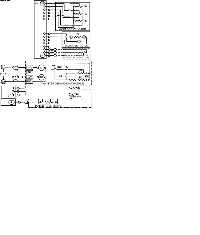
In addition to the unit status switch inputs, the processor board also accepts inputs from several potentiometers. These potentiometers control various operational characteristics of the system. Inputs are received by the processor through pin terminal connector J3. See Fig. 4.
All of the potentiometers must be set before the unit is started in order for the unit to function properly. See StartUp, Potentiometers section on page 28 for information on establishing set points. Each of the potentiometers has a valid range that is used by the control. The valid range is de®ned as the potentiometer's resistance value that the control will not consider to be in error. This is usually between 10% and 90% of the potentiometer's total resistance. The control has been programmed to accept an operational range for the potentiometer, which may not be the same as the valid range.
3
|
|
LEGEND |
|
|
CR |
Ð Control Relay |
|
LEGEND |
EC |
Ð Enthalpy Control |
|
LPS Ð Low-Pressure Switch |
|||
T Ð Thermistor |
|||
|
Fig. 3 Ð Pin Terminal Connector J2 |
||
Field Wiring |
|
||
Accessory |
|
Status Switch Inputs |
|
Fig. 2 Ð Pin Terminal Connector J1
Thermistor Inputs
Table 2 Ð Pin Terminal Connector J2
Status Switch Inputs
|
CONNECTOR J2 |
|
STATUS SWITCH |
UNIT SIZE |
|
TERMINAL NO. |
|
034-104 |
|
|
|
|
||
|
1,2 |
|
Oil Pressure, |
Jumpered |
|
|
Circuit 2 |
||
|
|
|
|
|
|
3,4 |
|
Oil Pressure, |
Jumpered |
|
|
Circuit 1 |
||
|
|
|
|
|
|
7,8 |
|
Loss Of Charge, |
LPS2 |
|
|
Circuit 2 |
||
|
|
|
|
|
|
9,10 |
|
Loss of Charge, |
LPS1 |
|
|
Circuit 1 |
||
|
|
|
|
|
|
13,14 |
|
Economizer |
EC |
|
|
Changeover |
||
|
|
|
|
|
|
15,20 |
|
Compressor Fault |
CR2 |
|
|
Signal |
||
|
|
|
|
|
|
15,24 |
|
Compressor Fault |
CR1 |
|
|
Signal |
||
|
|
|
|
|
|
LEGEND |
|
|
|
CR |
Ð Control Relay |
|
|
|
EC |
Ð Enthalpy Control |
|
|
|
LPS Ð Low-Pressure Switch
NOTE: Terminal numbers 5, 6, 11, 12, 16-19, and 21-23 are not used on these units.
|
LEGEND |
|
IN |
Ð Input |
Factory Wiring |
P |
Ð Potentiometer |
Field Wiring |
RNT Ð Return |
Accessory |
|
SW |
Ð Switch |
|
Fig. 4 Ð Pin Terminal Connector J3
Potentiometer Inputs
4
The potentiometer locations and functions are as follows:
P1 Ð SUPPLY-AIR SET POINT Ð This potentiometer is located on the display board. The supply-air set point is the cooling mode control temperature which the VAV control system will attempt to maintain at Thermistor T1 by control of economizer position and/or cycling unloaders and compressors.
P2 Ð ECONOMIZER POSITION Ð Economizer feedback potentiometer is located on the economizer motor. The microprocessor is programmed to indicate an alarm if the travel during initialization is less than 10% of the total potentiometer's resistance. An alarm condition will also be signaled if the potentiometer fails during operation, indicating that the damper blades are stuck. If either situation occurs, the processor will try to drive the economizer dampers closed.
P3 Ð RESET LIMIT Ð This potentiometer is located on the accessory board (provided standard from the factory) in the unit main control box and establishes the maximum amount of reset that can be applied to the supply-air set point (P1). Reset is limited by the P1 default of 70 F. This potentiometer is used only when accessory, ®eld-installed temperature reset is used. If temperature reset is used, DIP (dual, in-line package) switch 2 must be in the ON position.
P4 Ð DEMAND LIMIT Ð This potentiometer is located near TRAN4 in the unit control box. The demand limit potentiometer is used only if accessory, ®eld-installed demand limit is used, and if DIP switch 5 is in the ON position. For single-step demand limit, a ®eld-installed 5 to 20 Kohm potentiometer and switch must be used.
P5 Ð ECONOMIZER MINIMUM POSITION Ð This potentiometer is on the accessory board (provided standard from the factory) located in the unit main control box. This potentiometer speci®es the minimum opening position for the optional economizer. If a fault condition is detected by the processor, an alarm condition will be signaled and the economizer dampers will close.
P6 Ð WARM-UP SET POINT Ð This potentiometer is on the accessory board (provided standard from the factory) located in the unit main control box. This potentiometer establishes the set point temperature for the Morning Warm-Up function. When the temperature is reached, Morning Warm-Up is terminated and VAV operation begins. DIP switch 4 must be in the ON position if morning warm-up heat is to be used.
P7 Ð SASP (SUPPLY AIR SET POINT) RESET TEMPERATURE Ð This 10 Kohm potentiometer is used only if the accessory, ®eld-installed temperature reset package is installed. This potentiometer determines the temperature at which reset will begin. It is located on the accessory temperature reset board. DIP switch 2 must be in the ON position to enable SASP reset.
PROCESSOR BOARD OUTPUTS Ð The processor board also controls outputs through the relay board. The relay board plugs into the processor board using a ribbon cable.
In addition, the processor board controls the display board. The display board is connected to the processor board by a ribbon cable, and has an LED (light-emitting diode) display showing the status of the unit and diagnostic information.
CONFIGURATION HEADER AND DIP SWITCH ASSEMBLY Ð The processor board is programmed to control a variety of air conditioning units. To tailor the processor to the particular unit being controlled, 2 devices are used. One is the con®guration header, and the other is the DIP switch assembly.
The con®guration header (part no. 30GB660001) is a series of 8 small wires that are broken or unbroken in a pattern to indicate several unique characteristics of the unit. The con®guration header is factory set and should not be changed. Changing the factory setting may cause the unit to malfunction.
The DIP switches con®gure the unit for several ®eldinstalled options, as well as for several other options that may be unique to the unit. The DIP switches are located under a plastic enclosure which must be removed for access. The switches can be ®eld adjusted, but must be adjusted only when the unit control circuit breaker is off.
Relay Board Ð The relay board is used to control 24-v and 115-v loads. See Fig. 5. The relay board is connected to the processor board by a ribbon cable at pin J9. Electrical connections to the relay board are made through pins J5 (115 v) and J6 (24 v). The relay board has eight 24-v relays and ®ve 115-v relays. See Table 3.
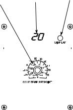
Display Board Ð The display board is located in the main unit control box and is connected to the J10 port of the processor board through a ribbon cable. The display board contains the supply-air set point potentiometer P1; a 2-digit, LED display; and the display button (see Fig. 6). The LED display is used to convey the operating information and operational error codes.
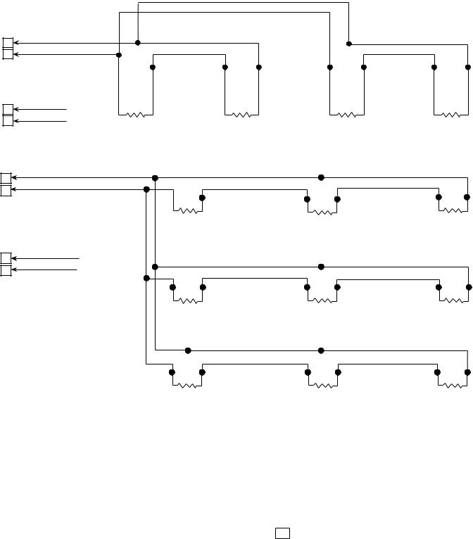
Thermistors Ð The processor uses up to 5 thermistors to sense the temperatures at various points in the system. See Table 1 and Fig. 7-14. All the thermistors have identical temperature versus resistance and voltage drop characteristics, and are monitored by the processor for a short or open circuit. The valid range for a thermistor is 362,640 to 219 ohms. Thermistor details and locations are as follows:
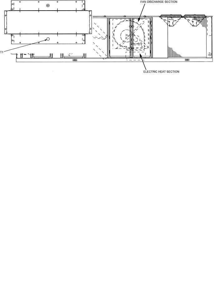
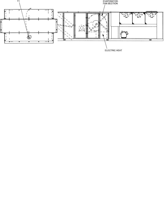
T1 Ð SUPPLY-AIR TEMPERATURE THERMISTOR Ð This thermistor is located in the unit supply fan discharge. It provides information for the processor to stage the number of capacity steps required to maintain a desired supplyair temperature.
T2 Ð RETURN-AIR TEMPERATURE THERMISTOR Ð This thermistor is located in the mixed-air portion of the unit cabinet. The thermistor's primary function is to provide morning warm-up information. This sensor will also provide differential information for the processor during cooling operation (such as the rate of change for a capacity step).
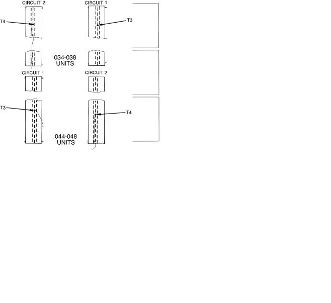
T3 Ð SATURATED CONDENSING TEMPERATURE, CIRCUIT 1 Ð This thermistor is located on the condenser coil return bend. See Fig. 13 and 14. It controls the staging of the unit condenser fans based on the condensing temperature of the refrigerant at the designated position on the condenser coil.
T4 Ð SATURATED CONDENSING TEMPERATURE, CIRCUIT 2 Ð This thermistor is located on the condenser coil return bend. See Fig. 13 and 14. It controls the staging of the unit condenser fans based on the condensing temperature of the refrigerant at the designated position on the condenser coil.
T10 Ð RESET TEMPERATURE Ð This thermistor is used only if the accessory temperature reset package is used. It provides occupied space temperature information to the processor, which determines whether or not reset is required. The thermistor is remotely mounted outside the unit in the conditioned space.
5
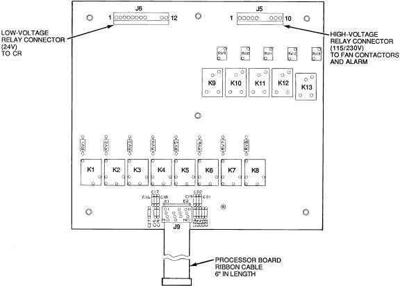
Table 3 Ð Output Pin and Terminal Assignments
OUTPUT PIN- |
NAME |
RATING |
DEVICE |
|
TERMINAL |
||||
|
|
|
||
J6-1 |
Stage 1 |
|
CR1 |
|
Compressor Relay (K1)* |
|
|||
|
|
|
||
J6-2 |
Stage 2 |
|
U2** |
|
Compressor Relay (K2)* |
|
|||
|
|
|
||
J6-3 |
Stage 3 |
|
U1 |
|
Compressor Relay (K3)* |
|
|||
|
|
|
||
J6-4 |
Stage 4 |
24 vac |
Not Used |
|
Compressor Relay (K4)² |
||||
|
|
|
||
J6-5 |
Stage 5 |
|
CR2 |
|
Compressor Relay (K5)² |
|
|||
|
|
|
||
J6-6 |
Stage 6 |
|
Not Used |
|
Compressor Relay (K6)² |
|
|||
|
|
|
||
J6-7 |
Economizer Open Relay (K7) |
|
EOR |
|
J6-8 |
Economizer Close Relay (K8) |
|
ECR |
|
J5-1 |
Supply Fan Relay (K9) |
|
IFC |
|
J5-2 |
Morning Warm-Up Relay (K10) |
|
HIR |
|
J5-3 |
Stage 1 Condenser |
|
OFC2/OFC3 ²² |
|
Fan Relay (K11) |
115 vac |
|||
|
|
|||
J5-4 |
Stage 2 Condenser |
|
OFC4 \ |
|
Fan Relay (K12) |
|
|||
|
|
|
||
J5-5 |
External Alarm Relay (K13) |
|
ALM |
|
|
|
|
|
|
LEGEND |
ALM Ð Alarm |
|
CR |
Ð Control Relay |
ECR Ð Economizer Close Relay |
|
EOR Ð Economizer Open Relay |
|
HIR |
Ð Heat Interlock Relay |
IFC |
Ð Indoor (Evaporator) Fan Contactor |
OFC |
Ð Outdoor (Condenser) Fan Contactor |
U |
Ð Unloader |
*Circuit 1. ²Circuit 2.
**U2 is not used on 044 units.
²²OFC2 on 034-048 units; OFC3 on 054-104 units. \ Used on 054-104 units only.
LEGEND
CR Ð Control Relay
JÐ Terminal Pin Connectors
KÐ Relay
Fig. 5 Ð Relay Board
6
P1 SUPPLY AIR |
TWO-DIGIT |
DISPLAY |
||||||||||
SET POINT |
DISPLAY |
BUTTON |
||||||||||
POTENTIOMETER |
|
|
|
|
|
|
|
|
|
|
||
|
|
|
|
|
|
|
|
|
|
|
|
|
|
|
|
|
|
|
|
|
|
|
|
|
|
|
|
|
|
|
|
|
|
|
|
|
|
|
|
|
|
|
|
|
|
|
|
|
|
|
|
|
|
|
|
|
|
|
|
|
|
|
|
|
|
|
|
|
|
|
|
|
|
|
|
|
|
|
|
|
|
|
|
|
|
|
|
|
|
|
|
|
|
|
|
|
|
|
|
|
|
|
|
|
|
|
|
|
|
|
|
|
|
|
|
|
|
|
|
|
|
|
|
|
|
|
|
|
|
|
|
|
|
|
|
|
|
|
|
|
|
|
|
|
|
|
|
|
|
|
|
|
|
|
|
|
|
|
|
|
|
|
|
|
|
|
|
|
Fig. 6 Ð Display/Set Point Board
Compressor Operation
CONTROL RELAY (CR) Ð This relay provides information to the processor about compressor operation (one control relay per compressor). The relay controls and protects the compressor and also controls the crankcase heater.
A control signal to check the safety statuses and to start the compressor is sent from the relay board. This signal travels through all of the safeties: the high-pressure switch, and the internal protector (where used) and on to the control relay coil. Once the control relay coil has been energized, the control relay completes a feedback circuit for the processor, informs the processor of the status of the compressor safeties, energizes the compressor contactor coil, and deenergizes the crankcase heaters. A fault will be detected by the processor if the control relay opens during operation or startup. The processor will lock the compressor or the circuit off by deenergizing the appropriate relay(s) on the relay board and energizing an alarm signal.
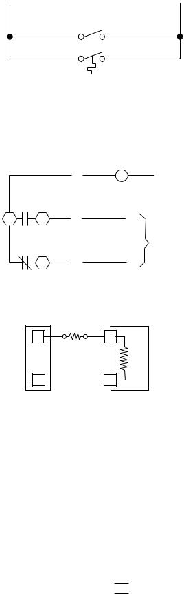
Accessory Board Ð The accessory board is standard (factory supplied) in the VAV rooftop units. See Fig. 15. This board is located in the control box of each unit. Each board has a prewired connector supplied with it to connect directly to the processor board. It has 3 potentiometers: P3, P5, and P6.
P3 Ð RESET LIMIT Ð The processor board is programmed for occupied space temperature reset. In order for reset to work, the accessory temperature reset board must be used. Potentiometer P3 is the maximum set point temperature to which the supply air can be reset.
P5 Ð ECONOMIZER MINIMUM POSITION Ð This potentiometer controls the set point for the minimum position of the economizer.
P6 Ð MORNING WARM-UP TEMPERATURE Ð This potentiometer controls the morning warm-up temperature set point.
Single-Step Demand Limit Ð The single step demand limit provides a means to limit the capacity of the VAV unit using an external switch. Single step demand limit will limit the compressor displacement based on the ratio of the wiper arm to the full scale resistance. The exact percentage of capacity reduction differs depending on the number of capacity steps.
A 3-wire, 5 to 20 Kohm, ®eld-supplied potentiometer (P4) is required for this option. The potentiometer should be wired to the processor J3 connections. In order to control the demand limit, the wiper arm of the potentiometer should be switched open and closed based on the demand limit requirement. The control switch is also ®eld-supplied and installed.
If the wiper arm wire is open, all capacity stages can be used. When the wiper arm wire is closed, the capacity is reduced by the amount set on potentiometer P4.
Demand Limit Control Module (DLCM) Ð The DLCM provides a 2-step demand limit control using an external switch. The ®rst step is between 50% and 100% of the maximum compressor displacement. See Fig. 16. The second step is between 0% and 49% of the maximum compressor displacement. The exact percentage differs depending on the number of capacity steps.
Two adjustable potentiometers are used to set the 2 demand limit points. Potentiometer P1 is used to set a demand limit between 50% and 100% of the unit capacity. Potentiometer P2 is used to set a demand limit between 0% and 49% of unit capacity.
If no power is supplied to the demand limit control module, all capacity stages can be used. When power is supplied to terminal IN1 only, the ®rst step of the demand limit control is energized and the capacity is reduced by the amount set on potentiometer P1. When power is supplied to terminal IN2 only, or to both IN1 and IN2, the capacity is reduced by the amount set on potentiometer P2.
7
GAS SECTION |
HORIZONTAL SUPPLY SECTION |
(48FK,JK ONLY) |
(50FY,JY ONLY) AND EXTENDED |
|
PLENUM SECTION (50FKX,FKY,JKX,JKY) |
Fig. 7 Ð Thermistor T1 Location, 48FK,JK, 50FY,JY and 50FKX,FKY,JKX,JKY 034-048 Units
FAN DISCHARGE/ELECTRIC HEAT SECTION
Fig. 8 Ð Thermistor T1 Location, 50FK,JK034-048 Units
8
GAS SECTION |
HORIZONTAL DISCHARGE SECTION (50FY,JY) |
(48FK,JK) |
AND EXTENDED |
|
PLENUM SECTION (50FKX,FKY,JKX,JKY) |
Fig. 9 Ð Thermistor T1 Location, 48FK,JK, 50JY and 50JKX,JKY 054-074 Units and 50FKX,FKY and 50FY054-104 Units
FAN DISCHARGE/ELECTRIC HEAT SECTION
Fig. 10 Ð Thermistor T1 Location, 50FK,JK054-074 Units
9
STANDARD |
BAG |
FILTERS |
FILTERS |
Fig. 11 Ð Thermistor T2 Location, Size 034-048 Units
STANDARD FILTERS |
BAG FILTERS |
|
(054-074 Only) |
Fig. 12 Ð Thermistor T2 Location, Size 054-104 Units
Economizer Ð Economizer control is used to control the outside and return air dampers of the unit, to satisfy space cooling demand using all outside air (when permitted), and to satisfy cooling in conjunction with compressor operation (when conditions permit). During Occupied periods without cooling demand, the outside-air dampers will be at the usercon®gured Minimum Damper Position (at P5 on accessory board). During Unoccupied periods, the outside-air dampers will be closed.
The economizer is available as a factory-installed option. The user can install an accessory differential enthalpy sensor to enhance economizer control. Refer to the installation section for ®eld wiring of the sensor.
Fig. 13 Ð Thermistor T3 and T4 Locations,
Size 034-048 Units
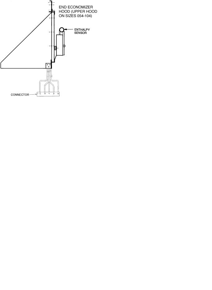
ENTHALPY CONTROL Ð Outside air enthalpy control is standard with the factory-installed economizer option. Enthalpy is sensed by a controller located behind the end outside air hood. The control can be accessed by removing the upper hood ®lter. See Fig. 17.
DIFFERENTIAL ENTHALPY Ð Added efficiencies in economizer control can be gained by installing a differential enthalpy sensor in the return air duct. When differential enthalpy control is installed, the economizer control will use the air stream with lower enthalpy (outside air or return air) to provide for lower compressor operating costs during integrated economizer cycle operation. The differential enthalpy sensor is installed in the return-air duct.
10
054 UNITS
064, 074, 078 UNITS
088, 104 UNITS
Fig. 14 Ð Thermistor T3 and T4 Locations, Size 054-104 Units
11
|
LEGEND |
ECON Ð Economizer |
|
MIN |
Ð Minimum |
P |
Ð Potentiometer |
VAV |
Ð Variable-Air Volume |
Fig. 15 Ð Accessory Relay Board
(Standard; Factory Supplied)
|
|
LEGEND |
IC |
Ð |
Integrated Circuit |
IN |
Ð |
Input |
P |
Ð Potentiometer |
|
RTN Ð Return
Fig. 16 Ð Two-Step Demand Limit Module
Fig. 17 Ð Enthalpy Sensor Location
Variable Frequency Drive (VFD) Ð The optional VFD is used to modulate supply fan air¯ow to maintain duct static pressure on VAV applications. The VFD is located in the supply fan section (see Fig. 18 and 19), and can be accessed by opening the fan section access door.
The unit is supplied with a pressure transducer capable of measuring from 0.0 to 5.0 in. wg. The pressure transducer will send a 4 to 20 mA signal to the VFD to modulate the speed of the indoor fan motor to precisely control the fan to the desired static pressure set point. The VFD is factory set at 2.5 in. wg duct static pressure. Refer to the Operating Sequence section for more information on the VFD.
The VFD has been programmed and wired at the factory for this application. No further adjustments (except for Duct Static Pressure Set Point) should be necessary at start-up. Factory jumper wire con®gurations are shown in the Supply Fan Control with VFD Option section on page 28.
A separate service manual for the factory-installed VFD is supplied with each unit. Refer to the VFD manual for more information on the VFD controls.
Temperature Reset Ð Accessory temperature reset allows the unit to automatically adjust (``reset'') the supplyair temperature set point to a higher value once most of the space cooling load has been met. When the space conditions are satis®ed, the VAV terminals will close to the minimum position. All VAV units will sense the decrease in actual supplyair temperature and the unit controls respond by reducing
Fig. 18 Ð Variable Frequency Drive,
Sizes 034-048 and 078-104
Fig. 19 Ð Variable Frequency Drive, Sizes 054-074
12

capacity stages to maintain user-established supply-air set point temperature. When VAV units are also equipped with optional supply duct pressure controls (either inlet guide vanes [IGV] or variable frequency drive package), the unit also senses an increase in duct static pressure and responds by closing IGV dampers or slowing fan wheel speed to maintain usercon®gured set points for supply duct pressure. Allowing the supply-air temperature to be reset to a higher value maintains air circulation in the space without costly overcooling.
The accessory package is required for temperature reset. The accessory includes:
·thermistor T10, to monitor space temperature
·reset temperature potentiometer P7, to establish start temperature for reset operation
·reset limit potentiometer P3, to establish maximum level of modi®ed supply-air temperature
More than one space sensor may be used if an average space temperature is desired for initiating temperature reset. Refer to installation section for sensor part number and wiring schematic.
Temperature reset will start when space temperature (at T10) drops to the set point at P7. When Temperature Reset is active, the LED (light-emitting diode) display will show
code 21 . Automatic adjustment of supply-air temperature
set point will end when modi®ed SASP equals reset limit set point at P3. (See formula for automatic modi®cation of SASP in Controls Installation, Space Temperature Reset section on this page.)
CONTROLS INSTALLATION
The VAV units may be used in applications with additional control features, options, or accessories. Refer to the appropriate accessory installation instructions for more information on installing that accessory. Unit control box component arrangement is shown in Fig. 20-22. Control options and accessories available for VAV units are:
·smoke control modes
·differential enthalpy sensor
·electric heaters (sizes 034-074 only)
·modulating power exhaust
·Motormastert I control
·space temperature reset
·night setback thermostat (®eld-supplied)
·single step demand limit
·two-step demand limit
·inlet guide vanes
·variable frequency drive
·variable frequency drive remote display kit
Control Wiring Ð A switch or timeclock (®eld supplied) must be wired in to control when unit will go into and out of Occupied mode. Connect switch or timeclock between terminals 1 and 2 on terminal block 3 (sizes 034-048) or terminal block 4 (sizes 054-104) in unit control box. See Fig. 23. The circuit potential is 24 v.
Variable air volume units equipped with warm-up heat require that room terminals be controlled to go fully open when unit goes into the Heating mode. Heating interlock relay (HIR) is provided for this function. The relay is located in the unit control box. When unit goes into Heating mode, interlock relay is energized providing switch closure or opening (depending on how ®eld power source is set up) to open the room terminals. Field connections for interlock relays are terminals 3 and 4 (for normally open contacts) and terminals 3 and 7 (for normally closed contacts) on terminal block 3 (sizes 034-048) or terminals block 4 (sizes 054-104). See Fig. 24. Note that a ®eld-supplied power source is required.
There are no required 115-volt ®eld wiring connections, therefore no provisions have been made in the unit for running 115-volt wiring. If any of the ®eld-installed options requiring 115-volt connections are desired, the unit must be modi®ed in the ®eld for 115-volt wiring.
NIGHT SETBACK THERMOSTAT Ð Wire ®eld-supplied thermostat (suitable for 24-v circuit) between terminals 1 and 2 on terminal block 3 (sizes 034-048) or terminal block 4 (sizes 054-104). This thermostat is used to bypass the timeclock occupied/unoccupied switch and is used to operate unit during unoccupied times at more economical temperatures. (See Fig. 23.)
SPACE TEMPERATURE RESET ACCESSORY (50DJ900021) Ð Consists of a thermistor (T10) and a reset board with a potentiometer (P7) that is used to set space temperature at which reset starts. Mount reset board in unit control box or other convenient place. Wire thermistor in series with P7 and connect to terminals 12 and 15 on terminal block 3 (sizes 034-048) or terminal block 4 (sizes 054-104) in unit control box. If there is a long run to conditioned space, it is necessary to splice additional wire to thermistor. The reset board has 2 pressure connectors for ®eld wiring. (See Fig. 25).
Space Temperature Reset
INSTALLATION Ð Install the accessory temperature reset package in accordance with instructions provided with the accessory kit.
Mount the reset board in the unit control box (or other suitable location) per instructions.
Locate the thermistor T10 in a suitable location in the occupied space per instructions.
Wire T10 to the reset board and to the unit control terminal block per Fig. 25. Wire the other terminal on the reset board to the unit control terminal block per Fig. 25.
If multiple sensors are required to average the space temperature, see Fig. 26. Use only Carrier Part Number HH79NZ014 sensor, in arrangements of 4 or 9 sensors, with total wiring not to exceed 1000 ft.
To enable reset function, change DIP (dual in-line package) switch 2 to position ON. (Disconnect control power before changing DIP switch positions; reconnect power after all changes have been made.)
CONFIGURATION Ð Set points for reset operation are established at potentiometers P7 and P3 (on the reset board).
Potentiometer P7 Ð Reset temperature set point (temperature at which reset function will start). Maximum of 80 F, minimum 0° F. Set below normal room cooling set point level to sense overcooling in the occupied space.
NOTE: It is difficult to accurately set the P7 potentiometer to the desired set point. Use the procedure below.
Proper setting of the P7 potentiometer may be made on a resistance basis. The microprocessor initiates reset when it detects a resistance of the thermistor plus the potentiometer of 13,084 ohm. The potentiometer set point may be calculated using the following formula:
P7R = 13,084 ± T10R
Where: |
|
P7R = |
the desired set point of the P7 potentiometer in ohms |
T10R = |
the resistance of the T10 thermistor for the desired |
|
set point |
13

14
Fig. 20 Ð Unit Control Box Arrangement, Sizes 034-048

15
Fig. 21 Ð Unit Control Box Arrangement, Sizes 054-078

16
Fig. 22 Ð Unit Control Box Arrangement, Sizes 088 and 104
034-048: TB3 |
034-048: TB3 |
||||||
054-104: TB4 |
054-104: TB4 |
||||||
|
|
|
|
|
|
|
|
|
|
1 |
|
|
2 |
|
|
|
|
|
|
|
|
|
|
|
|
|
|
|
|
|
|
|
|
|
|
OCCUPIED/UNOCCUPIED |
|||
|
|
|
|
SWITCH |
|||
NIGHT SETBACK THERMOSTAT
NOTES:
1.Occ/Unocc switch closes when occupied.
2.Night setback thermostat closes when in night setback heating.
Fig. 23 Ð Occupied/Unoccupied Switch with Night Setback Thermostat
|
|
034-048: TB3 |
|
|
||||
|
|
054-104: TB4 |
|
FIELD |
||||
|
|
|
|
|
|
|
|
SUPPLIED |
|
|
|
|
3 |
|
|
V |
POWER |
4 |
6 |
|
|
|
|
|
|
SOURCE |
|
|
|
|
|
|
|||
|
|
|
|
|
N.O. |
|||
|
|
4 |
|
|
|
|||
|
|
|
|
|
|
|
|
SIGNAL |
|
|
|
|
|
|
|
|
|
|
|
|
|
|
|
|
|
TO ROOM |
|
|
|
|
|
|
|
|
TERMINALS |
|
|
|
|
|
|
|
N.C. |
|
|
5 |
|
|
7 |
|
|
|
|
|
|
|
|
|
|
|
|
|
Fig. 24 Ð Heat Interlock Relay
034-048: TB3
054-104: TB4
T10
12
RESET
P7 BOARD
15 

Fig. 25 Ð Accessory Reset Board
EXAMPLE:
T10 desired set point is 70 F.
T10R from Table 4 for 70 F is 5929 ohms. P7R = 13,084 ± 5929
P7R = 7155 ohms
Using an ohmmeter, set the P7 potentiometer to 7155 ohms to achieve a reset initiation set point of 70 F.
Potentiometer P3 Ð Reset limit set point (maximum temperature value for modi®ed supply air set point). Maximum of 70 F, minimum 40 F. Set between leaving air set point (P1) and 70 F (maximum range permitted by control).
OPERATING SEQUENCE Ð If space temperature is above reset set point (T10 > P7), no reset will occur.
If space temperature is equal to or less that reset set point
(T10 < P7), the LED will display 20 and reset will begin.
Control will automatically adjust leaving air temperature by the following formula:
MSP = SP + [(P3 - SP) / 3] x (P7 − T10) |
|
||||
where: |
|
|
|
|
|
MSP = Modi®ed Leaving-Air Set Point |
|
||||
SP |
= Supply-Air Set Point |
|
|||
P3 |
= Maximum Supply-Air Temperature (reset limit) |
||||
P7 |
= Reset Initiation Temperature (reset set point) |
||||
T10 |
= Actual Space Temperature |
|
|||
3 |
= Ratio for reset (F) (®xed parameter) |
|
|||
|
Table 4 Ð Thermistor Resistance and |
||||
|
|
Voltage Drop Characteristics |
|||
|
|
|
|
|
|
|
TEMP |
|
RESISTANCE |
|
VOLTAGE |
|
(F) |
|
(Ohms) |
|
DROP (v) |
|
31.0 |
|
16813.8 |
|
3.582 |
|
32.0 |
|
16345.7 |
|
3.553 |
|
33.0 |
|
15892.2 |
|
3.523 |
|
34.0 |
|
15452.7 |
|
3.494 |
|
35.0 |
|
15026.7 |
|
3.464 |
|
36.0 |
|
14613.9 |
|
3.434 |
|
37.0 |
|
14213.6 |
|
3.404 |
|
38.0 |
|
13825.5 |
|
3.373 |
|
39.0 |
|
13449.2 |
|
3.343 |
|
40.0 |
|
13084.2 |
|
3.312 |
|
41.0 |
|
12730.1 |
|
3.281 |
|
42.0 |
|
12386.6 |
|
3.250 |
|
43.0 |
|
12053.3 |
|
3.219 |
|
44.0 |
|
11730.0 |
|
3.187 |
|
45.0 |
|
11416.1 |
|
3.156 |
|
46.0 |
|
11111.5 |
|
3.124 |
|
47.0 |
|
10815.8 |
|
3.093 |
|
48.0 |
|
10528.7 |
|
3.061 |
|
49.0 |
|
10250.0 |
|
3.029 |
|
50.0 |
|
9979.3 |
|
2.997 |
|
51.0 |
|
9716.5 |
|
2.965 |
|
52.0 |
|
9461.3 |
|
2.933 |
|
53.0 |
|
9213.4 |
|
2.901 |
|
54.0 |
|
8972.6 |
|
2.869 |
|
55.0 |
|
8738.6 |
|
2.837 |
|
56.0 |
|
8511.4 |
|
2.805 |
|
57.0 |
|
8290.6 |
|
2.772 |
|
58.0 |
|
8076.1 |
|
2.740 |
|
59.0 |
|
7867.7 |
|
2.708 |
|
60.0 |
|
7665.1 |
|
2.676 |
|
61.0 |
|
7468.3 |
|
2.644 |
|
62.0 |
|
7277.1 |
|
2.612 |
|
63.0 |
|
7091.2 |
|
2.581 |
|
64.0 |
|
6910.6 |
|
2.549 |
|
65.0 |
|
6735.1 |
|
2.517 |
|
66.0 |
|
6564.4 |
|
2.486 |
|
67.0 |
|
6398.6 |
|
2.454 |
|
68.0 |
|
6237.5 |
|
2.423 |
|
69.0 |
|
6080.8 |
|
2.391 |
|
70.0 |
|
5928.6 |
|
2.360 |
|
71.0 |
|
5780.6 |
|
2.329 |
|
72.0 |
|
5636.8 |
|
2.299 |
|
73.0 |
|
5497.0 |
|
2.268 |
|
74.0 |
|
5361.2 |
|
2.237 |
|
75.0 |
|
5229.1 |
|
2.207 |
|
76.0 |
|
5100.8 |
|
2.177 |
|
77.0 |
|
4976.0 |
|
2.147 |
|
78.0 |
|
4854.8 |
|
2.117 |
|
79.0 |
|
4736.9 |
|
2.088 |
|
80.0 |
|
4622.4 |
|
2.058 |
|
|
|
|
|
|
17
|
|
|
|
RED |
RED |
|
|
|
|
BLK |
BLK |
SIZES 034-048 |
|
|
|
|
|
TB3 |
RED |
|
|
RED |
RED |
12 |
|
|
|||
|
|
|
|
BLK |
|
15 |
BLK |
|
|
BLK |
|
|
|
|
|
|
|
TO ACCESSORY SPACE |
|
|
|
|
|
TEMPERATURE RESET |
|
|
|
|
|
CONTROL BOARD |
|
|
|
|
|
SIZES 054-104 |
|
|
|
|
|
TB4 |
|
|
|
|
|
12 |
|
|
|
|
|
15 |
|
SENSOR 1 |
SENSOR 2 |
SENSOR 3 |
|
|
|
||||
|
|
SPACE TEMPERATURE RESET Ð 4 SENSOR AVERAGING APPLICATION |
|||
SIZES 034-048 |
|
|
|
|
|
TB3 |
RED |
|
|
RED |
RED |
12 |
|
|
|||
BLK |
|
|
BLK |
BLK |
|
15 |
|
|
|||
|
|
|
|
|
|
TO ACCESSORY SPACE |
|
|
|
|
|
TEMPERATURE RESET |
|
|
|
|
|
CONTROL BOARD |
|
|
SENSOR 1 |
SENSOR 2 |
|
SIZES 054-104 |
|
BLK |
RED |
|
|
|
|
|
|
||
TB4 |
|
|
|
|
|
12 |
|
|
|
RED |
RED |
15 |
|
|
|
||
|
|
|
BLK |
BLK |
|
|
|
|
|
||
|
|
|
BLK |
SENSOR 4 |
SENSOR 5 |
NOTE: Sensor part number is HH79NZ014. |
RED |
|
|||
|
|
|
|||
|
|
|
|
RED |
RED |
|
|
|
|
BLK |
BLK |
|
|
|
|
SENSOR 7 |
SENSOR 8 |
SPACE TEMPERATURE RESET Ð 9 SENSOR AVERAGING APPLICATION
Fig. 26 Ð Space Temperature Sensor Averaging
SENSOR 4
SENSOR 3
SENSOR 6
SENSOR 9
Demand Limit Ð The demand limit function provides a means to limit the cooling capacity of the VAV unit using an external discrete switch function. When enabled by the closure of the external switch, the control will limit the available compressor staging capacity according to user set points established at demand limit potentiometer(s).
The unit controls support two types of demand limit: singlestep and 2-step control.
SINGLE-STEP DEMAND LIMIT Ð This function will limit the total compressor staging based on the ratio of the set point potentiometer's wiper arm position to the full scale resistance of the potentiometer. The exact percentage of capacity reduction differs depending on the number of capacity steps.
A ®eld-supplied potentiometer and control switch are required for this function. See installation section for speci- ®cation on potentiometer and ®eld wiring.
TWO-STEP DEMAND LIMIT Ð Two-step demand limit is provided with the installation of the accessory Demand Limit
Control Module kit plus installation of 2 ®eld-supplied control switches (SPST-NO each). This accessory control provides for a ®rst step reduction of 50% to 100% of the maximum compressor staging; the second step provides for reduction between 0% and 49%. The exact percentage of capacity reduction differs depending on the number of capacity steps.
When demand limit is active, the LED display will show
code 22 .
INSTALLATION
Single-Step Demand Limit Ð A 3-wire 5 to 20 K-ohm potentiometer must be ®eld-supplied and installed. A singlepole normally open switch is also required (®eld-supplied and -installed). Locate the potentiometer (designated P4) and the switch in a suitable location (external from the unit or in the unit control box).
18
 Loading...