


Humidifiers and
Humidistat
Visit www.carrier.com
Installation, Start-Up, and Operating Instructions
MODEL HUMCCLFP1025-A--
FAN-POWERED
HUMIDIFIER
|
MODEL HUMCCSFP1016-A-- |
|
MODEL HUMCCLBP2018-A-- |
FAN-POWERED |
|
HUMIDIFIER |
||
BYPASS HUMIDIFIER |
||
|
MODEL HUMCCWTR2019-A-- |
MODEL HUMCCSBP2017-A-- |
WATER-SAVER |
|
BYPASS HUMIDIFIER |
|
A98362
→ Humidifiers
NOTE: Read the entire instruction in manual applicable to specific unit before starting the installation.
This symbol → indicates a change since the last issue.
SAFETY CONSIDERATIONS
Improper installation, adjustment, alteration, service, maintenance, or use can cause explosion, fire, electrical shock, or other conditions which may cause personal injury or property damage. Consult a qualified installer, service agency, distributor, or branch for information or assistance. The qualified installer or agency must use factory-authorized kits or accessories when modifying this product. Refer to the individual instructions packaged with the kits or accessories when installing.
Follow all safety codes. Wear safety glasses and work gloves. Use quenching cloth for brazing operations. Have fire extinguisher available. Read these instructions thoroughly and follow all warnings or cautions attached to the unit. Consult local building codes and National Electrical Code (NEC) for special requirements.
Recognize safety information. This is the safety-alert symbol  . When you see this symbol on the unit and in instructions or manuals, be alert to the potential for personal injury.
Understand the signal words DANGER, WARNING, and CAUTION. These words are used with the safety-alert symbol. DANGER identifies the most serious hazards which will result in severe personal injury or death. WARNING signifies hazards which could result in personal injury or death. CAUTION is used to identify unsafe practices which would result in minor personal injury or product and property damage.
Before installing or servicing system, always turn off main power to system. There may be more than 1 disconnect switch. Turn off accessory heater power if applicable. Electrical shock can cause personal injury or death.
Unit must not be installed where freezing temperatures could occur. Do not install unit on the furnace or fan coil jacket. Do not install unit where ends of cooling coil could restrict airflow to the humidifier. Condensation damage could occur if home has closed-off, unheated rooms.
INSTALLATION OF HUMCCLBP2018-A--
BYPASS HUMIDIFIER
Carrier's HUMCCLBP2018-A-- bypass humidifier can be installed on either the supply or return plenum of a forced-air system. This unit requires an external bypass duct between the supplyand return-air ductwork.
It is recommended to install the humidifier where it can be easily serviced. If this humidifier is installed with a central cooling system the bypass duct must have a shutoff damper to close during the cooling season. Always install humidifier downstream of an electronic air cleaner.
Manufacturer reserves the right to discontinue, or change at any time, specifications or designs without notice and without incurring obligations.
Book |
1 |
4 |
PC 101 |
Catalog No. 03HU-MC1 |
Printed in U.S.A. |
Form HUM-1SI |
Pg 1 |
7-98 |
Replaces: 49-4SI |
Tab |
7a |
9a |
|
|
|
|
|
|
|
→Step 1ÐInspect Package and Check Equipment
Inspect contents of packaged humidifier. File claim with shipping company prior to installation if shipment is damaged or incomplete.
The package should contain:
1.Humidifier and media assembly
2.Humidistat
3.Template
4.Owner's Manual
5.Warranty Certificate
6.Solenoid valve with bridge rectifier
7.Saddle valve assembly with adapter
8.Four sheet metal screws
9.Foam tape
10.Water noise reducer (use for water pressure over 60 psi)
11.6-in. damper
12.Worm clamp for field-supplied drain tube
13.Humidifier maintenance instruction sticker
14.Carrier logo label
BYPASS UNITS
"N" COIL
DRILL (2) HOLES
IN DUCT
FOR #8 SHEETMETAL
SCREWS
BYPASS UNITS ONLY |
HORIZONTAL |
VERTICAL |
|
|
A98363 |
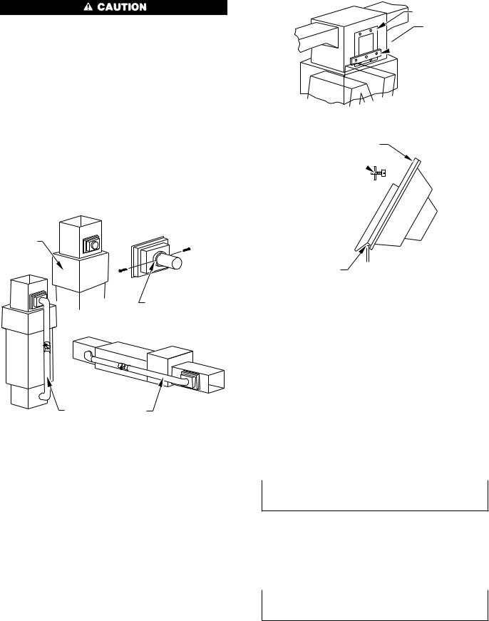
→ Fig. 1ÐInstallation of HUMCCLBP2018-A--
Bypass-Type Humidifier
Step 2ÐSelect Location (See Fig. 1.)
Humidifier may be installed on either supply or return plenum. If furnace has air conditioning coil, be sure humidifier does not interfere with coil ends. Remember to provide clearance for maintenance and evaporator pad removal.
Step 3ÐPrepare Plenum Opening (See Fig. 2.)
1.Use template for marking humidifier opening.
2.Tape in place on plenum making sure template is level.
IMPORTANT: For humidifier to operate properly it must be level and mounted on a vertical surface.
3.Drill four 1/8-in. holes in plenum.
4.Cut opening in plenum using heavy solid lines on template as a guide.
TEMPLATE
PLENUM
 LEVEL
LEVEL
A97096
Fig. 2ÐPreparing Plenum Opening
FOAM TAPE
SCREWS
NOTCH
A98364
→ Fig. 3ÐMounting the Humidifier
Step 4ÐMount the Humidifier (See Fig. 3.)
1.Attach foam tape on inside of mounting flange.
2.Hook bottom notch of humidifier on opening cut in plenum.
3.Push top of humidifier to plenum aligning screw holes with flange.
4.Align, level, and secure using top screws first.
5.Insert bottom screws and tighten all screws for air tight seal.
→Step 5ÐInstall Bypass Duct
Attach field-supplied 6-in. diameter duct, elbow, or starting collar with field-supplied 1/4-in. zip screws. Install supplied 6-in. damper in 6-in. duct connector.
IMPORTANT: On systems with central cooling, the damper should be closed during cooling season to prevent bypass air.
Do not support weight of bypass duct from humidifier Ð damage could result.
Step 6ÐInstall Drain Line
1.Use 1/2- or 5/8-in. vinyl tubing (field supplied) to connect drain on bottom of humidifier housing to an open drain.
→2. Use supplied worm clamp to hold drain tubing in position over drain fitting outlet.
Unit may leak if drain tubing is misapplied. Do not insert tubing inside of drain fitting outlet.
3.Make sure line is free of traps due to sagging and has sufficient pitch to drain.
2
HUMIDIFIER |
HUMIDISTAT |
BROWN |
24VAC |
|
|
BROWN |
FURNACE |
|
|
TRANSFORMER |
|
HUMIDIFIER |
HUMIDISTAT |
(FIELD SUPPLIED) |
|
|
RED |
|
115V |
|
BLU |
24V |
FIELD |
|
|
WIRING |
|
|
|
|
|
|
|
|
A98365 |
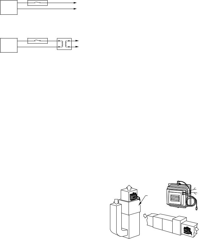
→ Fig. 4ÐInstallation of Humidistat on Bypass-Type Humidifier
Step 7ÐMake Water Connection
If garden hose is not used for water supply:
1.Mount saddle valve on water line according to instructions supplied with valve.
2.Run 1/4-in. diameter (water line grade) tubing from saddle valve to adapter on solenoid valve and tighten compression fittings.
IMPORTANT: If water pressure is higher than normal (60 psi), use noise suppression disk included in parts bag. (Read water noise reducer note located inside package for instructions.) For normal operation, saddle valve need only be opened 1 full turn to meet performance requirements.
3. Open valve and check installation for leaks.
NOTE: Saddle valve is self piercing on copper lines; 1/4-in. hole must be drilled in steel or iron pipes. Use only a grounded drill or a hand drill to avoid shock hazard. Turn off water and drain the pipe prior to drilling 1/4-in. hole.
Step 8ÐInstall Humidistat and Complete Wiring
1.Mount humidistat on inside wall, or return-air duct in accordance with section INSTALLATION OF HUMIDISTAT on page 10.
→2. Wire brown low voltage leads to furnace control board, or install a field-supplied step-down transformer 115vac/24vac 60Hz to power solenoid valve. (See Fig. 4.) Make sure bridge rectifier is attached to coil of solenoid valve.
NOTE: Wiring must comply with National Electrical Code and any local codes or ordinances that may apply.
Step 9ÐStart-Up
1.Open saddle valve to permit water flow to the solenoid.
2.Check all connections for water leaks.
3.Set thermostat to call for heat. Set humidistat for highest humidity setting making sure contacts are closed. After a few minutes of operation, check the drain connection for leaks and to see if water is flowing through humidifier.
4.Reverse thermostat and humidistat settings to insure proper shutdown.
5.Reset thermostat to normal setting. Reset humidistat to recommended setting.
Step 10ÐFinal Steps
Attach humidifier maintenance instruction sticker to a visible location.
1.Inform homeowner of proper operation, maintenance, and humidistat setting.
a.If unit is installed during cooling season, close bypass damper, set humidistat for summer setting (OFF or lowest setting).
b.If installed during heating season, set unit for normal operation.
INSTALLATION OF HUMCCLFP1025-A--
FAN POWERED HUMIDIFIER
Carrier's HUMCCLFP1025-A-- fan powered humidifier can only be installed on the supply plenum of a forced-air system. This unit requires an external 115-vac (fused) plug-in receptacle near the equipment for proper operation.
It is recommended to install the humidifier where it can be easily serviced. Pad access can be easily obtained from either the top or bottom of unit. Always install humidifier downstream of an electronic air cleaner.
→Step 1ÐInspect Package and Check Equipment
Inspect the contents of packaged humidifier. File claim with shipping company prior to installation if shipment is damaged or incomplete.
The package should contain:
1.Humidifier and media assembly
2.Humidistat
3.Template
4.Owner's Manual
5.Warranty Certificate
6.Solenoid valve
7.Saddle valve assembly with adapter
8.Four sheet metal screws
9.Foam tape
10.Water noise reducer (use for water pressure over 60 psi)
11.Worm clamp for field-supplied drain tube
12.Humidifier maintenance instruction sticker
13.Carrier logo label
RED
"N" COIL |
BLUE |
VERTICAL |
HORIZONTAL |
A98366
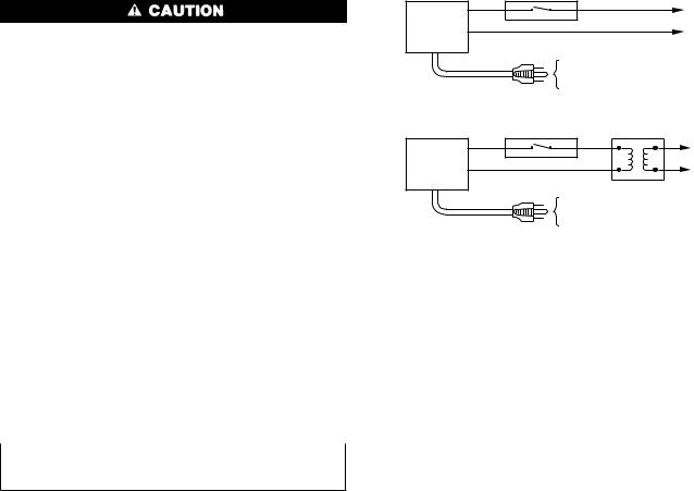
→ Fig. 5ÐInstallation of HUMCCLFP1025-A--
Fan-Type Humidifier
Step 2ÐSelect Location (See Fig. 5.)
Humidifier must be installed on supply plenum only. If furnace has air conditioning coil, be sure humidifier does not interfere with coil ends.
3
Remember to provide clearance for maintenance and evaporator pad removal. To access pad remove top or bottom cover to expose assembly (turn knob counter-clockwise).
Step 3ÐPrepare Plenum Opening (See Fig. 2.)
1.Use template for marking humidifier opening.
2.Tape in place on plenum making sure template is level.
IMPORTANT: For humidifier to operate properly it must be level and mounted on a vertical surface.
3.Drill four 1/8-in. holes in plenum.
4.Cut opening in plenum using heavy solid lines on template as a guide.
Step 4ÐMount the Humidifier (See Fig. 3.)
1.Attach foam tape on inside of mounting flange.
2.Hook bottom notch of humidifier on opening cut in plenum.
3.Push top of humidifier to plenum aligning screw holes with flange.
4.Align, level, and secure using top screws first.
5.Insert bottom screws and tighten all screws for air tight seal.
→Step 5ÐInstall Drain Line
1.Use 1/2- or 5/8-in. vinyl tubing (field supplied) to connect drain on bottom of humidifier housing to an open drain.
2.Use supplied worm drain clamp to hold drain tubing in position over drain fitting outlet.
Unit may leak if drain tubing is misapplied. Do not insert tubing inside of drain fitting outlet.
3.Make sure line is free of traps due to sagging and has sufficient pitch to drain.
Step 6ÐMake Water Connection
If garden hose is not used for water supply:
1.Mount saddle valve on water line according to instructions supplied with saddle valve.
2.Run 1/4-in. diameter (water line grade) tubing from saddle valve to adapter on solenoid valve and tighten compression fittings.
IMPORTANT: If water pressure is higher than normal (60 psi), use noise suppression disk included in parts bag. (Read water noise reducer note located inside package for instructions). For normal operation, saddle valve need only be opened 1 full turn to meet performance requirements.
3. Open valve and check installation for leaks.
NOTE: Saddle valve is self piercing on copper lines; 1/4-in. hole must be drilled in steel or iron pipes. Use only a grounded drill or a hand drill to avoid shock hazard. Turn off water and drain the pipe prior to drilling 1/4-in. hole.
Step 7ÐInstall Humidistat and Complete Wiring
1.Mount humidistat on inside wall, or return-air duct in accordance with section INSTALLATION OF HUMIDISTAT on page 10.
2.Wire red and blue low voltage. (See Fig. 6.)
3.Plug power cord in to 115-vac 60Hz source.
NOTE: Wiring must comply with National Electrical Code and any local codes or ordinances that may apply.
Step 8ÐStart-Up
1.Open saddle valve to permit water flow to the solenoid.
2.Check all connections for water leaks.
HUMIDIFIER |
HUMIDISTAT |
RED |
24VAC |
|
|
BLU |
FURNACE |
115V FIELD WIRING FAN TYPE UNITS ONLY
|
|
TRANSFORMER |
|
HUMIDIFIER |
HUMIDISTAT |
(FIELD SUPPLIED) |
|
|
RED |
|
115V |
|
BLU |
24V |
FIELD |
|
|
WIRING |
|
|
|
|
115V FIELD WIRING FAN TYPE UNITS ONLY
A96010
Fig. 6ÐInstallation of Humidistat on Fan-Type Humidifier
3.Set thermostat to call for heat. Set humidistat for highest humidity setting making sure contacts are closed. After a few minutes of operation, check the drain connection for leaks and to see if water is flowing through humidifier.
4.Reverse thermostat and humidistat settings to insure proper shutdown.
5.Reset thermostat to normal setting. Reset humidistat to recommended setting.
Step 9ÐFinal Steps
Attach humidifier maintenance instruction sticker to a visible location.
1.Inform homeowner of proper operation, maintenance, and humidistat setting.
a.If unit is installed during cooling season set humidistat for summer setting (OFF or lowest setting).
b.If installed during heating season, set unit for normal operation.
INSTALLATION OF HUMCCSFP1016-A--
FAN POWERED HUMIDIFIER
Carrier's HUMCCSFP1016-A-- fan powered humidifier can only be installed on the supply plenum of a forced-air system. This unit requires an external 115-vac (fused) plug-in receptacle near the equipment for proper operation.
It is recommended to install the humidifier where it can be easily serviced. Pad access door can be easily converted from right to the left hand side. Always install humidifier downstream of an electronic air cleaner.
→Step 1ÐInspect Package and Check Equipment
Inspect contents of packaged humidifier. File claim with shipping company prior to installation, if shipment is damaged or incomplete.
The package should contain:
1.Humidifier and media assembly
2.Humidistat
3.Template
4.Owner's Manual
5.Warranty Certificate
6.Solenoid valve
4
 Loading...