


HRVCCLHA, HRVCCSVU, HRVCCLVU
HRVCCSVA, HRVCCSHA
HEAT RECOVERY VENTILATOR
Owner’s Information Manual
HRVCCLHA Conventional Unit |
HRVCCSVU Compact Unit |
HRVCCLVU High Efficiency Unit |
HRVCCSVA Unit (Top Port) |
HRVCCSHA Unit (Side Port) |
Fig. 1 - Heat Recovery Ventilators
NOTE TO EQUIPMENT OWNER:
For your convenience, please record the model and serial numbers of your new equipment in the spaces provided. This information, along with the installation data and dealer contact information, will be helpful should your system require maintenance or service.
HEAT RECOVERY VENTILATOR
Model # _____________________________________
Serial # ______________________________________
ACCESSORIES (List type and model #)
_____________________________________________
_____________________________________________
INSTALLATION INFORMATION:
Date Installed ________________________________
DEALERSHIP CONTACT INFORMATION:
Company Name_______________________________
Address______________________________________
_____________________________________________
Phone Number _______________________________
NOTE TO INSTALLER:
This manual must be left with the equipment owner.
1
|
80 |
70 |
|
|
|
|
60 |
AIR EXCHANGE |
ON |
||
|
|
||||
|
|
|
ECHANGE´ |
D´AIR |
MARCHE |
|
|
|
50 |
|
|
OFF LOW HIGH |
|
|
|
|
|
MAX |
|
|
40 |
|
|
|
|
|
|
|
|
MIN |
|
|
|
|
|
INTERMITTENT |
20 |
30 |
|
|
|
|
25 |
|
|
|
|
|
|
|
|
|
|
|
% D´ HUMIDITE´ RELATIVE HUMIDITY |
|
|
||
|
|
|
OFF |
LOW |
|
ARRET |
BASSE HAUTE |
|
ARRET |
BASSE |
|
|
|
|
INTERMITTENT |
||
|
% HUM. RELATIVE HUM. |
EXT. TEMP. EXT. |
|
|
|
|
|
55% |
10°C/50°F |
|
|
|
|
45% |
0°C/32°F |
|
|
|
|
35% |
–10°C/14°F |
|
|
|
|
30% |
–20°C/–4°F |
|
|
|
|
|
MODE |
AIR EXCHANGE |
|
|
|
ECHANGE´ D´AIR |
|
|
|
|
% HUM. RELATIVE HUM. |
EXT. TEMP. EXT. |
|
50 |
40 |
55% |
10°C/50°F |
45% |
0°C/32°F |
||
60 |
30 |
35% |
–10°C/14°F |
|
|
30% |
–20°C/–4°F |
70 |
|
25 |
|
80 |
|
20 |
|
|
|
|
|
% D´HUMIDITE RELATIVE HUMIDITY
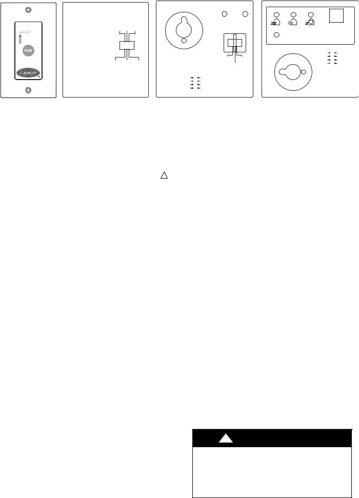
OneTouchTM Control |
Basic Control |
Standard Control |
Automatic Control |
|
|
|
(Not compatible with the following series: |
|
|
|
HRVCCSHA and HRVCCSVA) |
|
|
Fig. 2 - Controls |
A05360 |
|
|
|
SAFETY CONSIDERATIONS
Recognize safety information. This is the safety-alert symbol ! When you see this symbol on the unit and in instructions or manuals, be alert to the potential for personal injury.
Understand these signal words; DANGER, WARNING, and CAUTION. These words are used with the safety-alert symbol. DANGER identifies the most serious hazards which will result in severe personal injury or death. WARNING signifies hazards which could result in personal injury or death. CAUTION is used to identify unsafe practices which may result in minor personal injury or product and property damage. NOTE is used to highlight suggestions which will result in enhanced installation, reliability, or operation.
OPERATING YOUR HEAT RECOVERY
VENTILATOR (HRV) WITH ONETOUCHt CONTROL:
Press “PUSH” until the desired ventilation operation is selected. There are three selections: High, Low, Intermittent. The power indicator light indicates which mode has been selected.
High: This mode is recommended for the removal of excess pollutants and humidity. The ventilator will operate at its maximum speed continuously. The power indicator light will be lit red when this mode is selected.
Low: This mode is recommended for normal daily operation. The ventilator will operate at its minimum speed continuously. The power indicator light will be lit yellow when this mode is selected.
Intermittent: This mode is recommended when the inside air is too dry in the heating season or too humid in the cooling season. The ventilator will operate at its minimum speed for 20 minutes per hour and be off for 40 minutes per hour. The power indicator light will be lit green when this mode is selected.
Off: To turn the ventilator off, press “Push” until the power indicator light is turned off.
OPERATING YOUR HEAT RECOVERY VENTILATOR (HRV) WITH BASIC, STANDARD AND AUTOMATIC CONTROL
Your HRV is designed to operate as an integral part of your total heating and cooling system. With the exception of high capacity models, which are available with standard controls only, all HRVs offer 4 control options (See Fig. 2).
SBasic Controls: Allow the user to manually set the unit to lowor high-fan speed as required to maximize comfort. Controls may be unit mounted.
SStandard Controls: Offer automatic dehumidistat control and the option to select low speed or intermittent fan during heating season.
SAutomatic Controls: In addition to the operational features found with standard controls, automatic controls feature a recirculation mode. Not for use with forced-air HVAC systems.
Fan Speed Control—Enables user to modulate fan speed from low to high.
Dehumidistat Control—Allows the user to select the relative humidity level at which the unit would change fan speed to avoid condensation problems while heating during the winter months. (See Table 1).
Continuous Mode—If the relative humidity inside the building is lower than selected, air exchange would occur with the outside at low speed. If the relative humidity level inside the building is higher than selected, air exchange would occur outside at high speed. This ensures continuous air exchange for constant air quality.
Intermittent Mode—If the relative humidity inside the building is lower than selected, no air exchange would occur, and the system would turn off. If the relative humidity inside the building is higher than selected, air exchange would occur with outside at high speed. This ensures minimum air exchange level when the building is unoccupied to minimize operating cost.
Recirculation Mode—If the relative humidity inside the building is lower than selected, indoor air would be circulated and filtered at high speed. If the relative humidity inside the house is higher an selected, air exchange would occur with outside at high speed. This ensures continuous movement and filtration of air for maximum comfort.
!WARNING
ELECTRICAL SHOCK HAZARD
Failure to follow this warning could result in personal injury or death.
Before servicing system, always turn off main power to system. Turn off accessory heater power if applicable. There may be more than 1 disconnect switch.
2
 Loading...