


19XR 50/60 Hz Hermetic Centrifugal Liquid Chillers with HFC-134a
Installation Instructions
SAFETY CONSIDERATIONS
Centrifugal liquid chillers are designed to provide safe and reliable service when operated within design speci- ®cations. When operating this equipment, use good judgment and safety precautions to avoid damage to equipment and property or injury to personnel.
Be sure you understand and follow the procedures and safety precautions contained in the machine instructions, as well as those listed in this guide.
DO NOT VENT refrigerant relief devices within a building. Outlet from rupture disc or relief valve must be vented outdoors in accordance with the latest edition of ANSI/ASHRAE 15 (American National Standards Institute/American Society of Heating, Refrigeration and Air-Conditioning Engineers) (Safety Code for Mechanical Refrigeration). The accumulation of refrigerant in an enclosed space can displace oxygen and cause asphyxiation.
PROVIDE adequate ventilation in accordance with ANSI/ ASHRAE 15, especially for enclosed and low overhead spaces. Inhalation of high concentrations of vapor is harmful and may cause heart irregularities, unconsciousness, or death. Intentional misuse can be fatal. Vapor is heavier than air and reduces the amount of oxygen available for breathing. Product causes eye and skin irritation. Decomposition products are hazardous.
DO NOT USE OXYGEN to purge lines or to pressurize a machine for any purpose. Oxygen gas reacts violently with oil, grease, and other common substances.
DO NOT USE air to leak test. Use only refrigerant or dry nitrogen.
NEVER EXCEED speci®ed test pressures. VERIFY the allowable test pressure by checking the instruction literature and the design pressures on the equipment nameplate.
DO NOT VALVE OFF any safety device.
BE SURE that all pressure relief devices are properly installed and functioning before operating any machine.
RISK OF INJURY OR DEATH by electrocution. High voltage is present on motor leads even though the motor is not running when a solid state or inside-delta mechanical starter is used. Open the power supply disconnect before touching motor leads or terminals.
DO NOT WELD OR FLAMECUT any refrigerant line or vessel until all refrigerant (liquid and vapor) has been removed from chiller. Traces of vapor should be displaced with dry air or nitrogen and the work area should be well ventilated. Refrigerant in contact with an open ¯ame produces toxic gases.
DO NOT USE eyebolts or eyebolt holes to rig machine sections or the entire assembly.
DO NOT work on high-voltage equipment unless you are a quali®ed electrician.
DO NOT WORK ON electrical components, including control panels, switches, starters, or oil heater until you are sure ALL POWER IS OFF and no residual voltage can leak from capacitors or solid-state components.
LOCK OPEN AND TAG electrical circuits during servicing. IF WORK IS INTERRUPTED, con®rm that all circuits are deenergized before resuming work.
AVOID SPILLING liquid refrigerant on skin or getting it into the eyes. USE SAFETY GOGGLES. Wash any spills from the skin with soap and water. If liquid refrigerant enters the eyes, IMMEDIATELY FLUSH EYES with water and consult a physician.
NEVER APPLY an open ¯ame or live steam to a refrigerant cylinder. Dangerous over pressure can result. When it is necessary to heat refrigerant, use only warm (110 F [43 C]) water.
DO NOT REUSE disposable (nonreturnable) cylinders or attempt to re®ll them. It is DANGEROUS AND ILLEGAL. When cylinder is emptied, evacuate remaining gas pressure, loosen the collar, and unscrew and discard the valve stem. DO NOT INCINERATE.
CHECK THE REFRIGERANT TYPE before adding refrigerant to the machine. The introduction of the wrong refrigerant can cause machine damage or malfunction.
Operation of this equipment with refrigerants other than those cited herein should comply with ANSI/ASHRAE15 (latest edition). Contact Carrier for further information on use of this machine with other refrigerants.
DO NOT ATTEMPT TO REMOVE ®ttings, covers, etc., while machine is under pressure or while machine is running. Be sure pressure is at 0 psig (0 kPa) before breaking any refrigerant connection.
CAREFULLY INSPECT all relief valves, rupture discs, and other relief devices AT LEAST ONCE A YEAR. If machine operates in a corrosive atmosphere, inspect the devices at more frequent intervals.
DO NOT ATTEMPT TO REPAIR OR RECONDITION any relief valve when corrosion or build-up of foreign material (rust, dirt, scale, etc.) is found within the valve body or mechanism. Replace the valve.
DO NOT install relief devices in series or backwards.
USE CARE when working near or in line with a compressed spring. Sudden release of the spring can cause it and objects in its path to act as projectiles.
DO NOT STEP on refrigerant lines. Broken lines can whip about and release refrigerant, causing personal injury.
DO NOT climb over a machine. Use platform, catwalk, or staging. Follow safe practices when using ladders.
USE MECHANICAL EQUIPMENT (crane, hoist, etc.) to lift or move inspection covers or other heavy components. Even if components are light, use mechanical equipment when there is a risk of slipping or losing your balance.
BE AWARE that certain automatic start arrangements CAN ENGAGE THE STARTER, TOWER FAN, OR PUMPS. Open the disconnect ahead of the starter, tower fan, and pumps. Shut off the machine or pump before servicing equipment.
USE only repaired or replacement parts that meet the code requirements of the original equipment.
DO NOT VENT OR DRAIN waterboxes containing industrial brines, liquid, gases, or semisolids without the permission of your process control group.
DO NOT LOOSEN waterbox cover bolts until the waterbox has been completely drained.
DOUBLE-CHECK that coupling nut wrenches, dial indicators, or other items have been removed before rotating any shafts.
DO NOT LOOSEN a packing gland nut before checking that the nut has a positive thread engagement.
PERIODICALLY INSPECT all valves, ®ttings, and piping for corrosion, rust, leaks, or damage.
PROVIDE A DRAIN connection in the vent line near each pressure relief device to prevent a build-up of condensate or rain water.
Manufacturer reserves the right to discontinue, or change at any time, speci®cations or designs without notice and without incurring obligations.
Book |
2 |
|
PC 211 |
Catalog No. 531-940 |
Printed in U.S.A. |
Form 19XR-2SI |
Pg 1 |
10-97 |
Replaces: 19XR-1SI |
Tab |
5a |
|
|
|
|
|
|
|
|
|
|
|
|
|
|
|
|
|
|
CONTENTS
Page
SAFETY CONSIDERATIONS . . . . . . . . . . . . . . . . . . 1
INTRODUCTION . . . . . . . . . . . . . . . . . . . . . . . . . . . . . 2
General . . . . . . . . . . . . . . . . . . . . . . . . . . . . . . . . . . . . . 2
Job Data . . . . . . . . . . . . . . . . . . . . . . . . . . . . . . . . . . . . 2
INSTALLATION . . . . . . . . . . . . . . . . . . . . . . . . . . . . . 2-35
Receiving the Machine . . . . . . . . . . . . . . . . . . . . . . . 2
·INSPECT SHIPMENT
·IDENTIFY MACHINE
·PROVIDE MACHINE PROTECTION
Rigging the Machine . . . . . . . . . . . . . . . . . . . . . . . . . 2
·RIG MACHINE ASSEMBLY
·RIG MACHINE COMPONENTS
Install Machine Supports . . . . . . . . . . . . . . . . . . . . 17
·INSTALL STANDARD ISOLATION
·INSTALL ACCESSORY ISOLATION
·INSTALL SPRING ISOLATION
Connect Piping . . . . . . . . . . . . . . . . . . . . . . . . . . . . . 19
·INSTALL WATER PIPING TO HEAT EXCHANGERS
·INSTALL VENT PIPING TO
RELIEF VALVES
Make Electrical Connections . . . . . . . . . . . . . . . . 28
·CONNECT CONTROL INPUTS
·CONNECT CONTROL OUTPUTS
·CONNECT STARTER
·CARRIER COMFORT NETWORK INTERFACE
Install Field Insulation . . . . . . . . . . . . . . . . . . . . . . 35
INSTALLATION START-UP REQUEST
CHECKLIST . . . . . . . . . . . . . . . . . . . . . . . . CL-1, CL-2
INTRODUCTION
General Ð The 19XR machine is factory assembled, wired, and leak tested. Installation (not by Carrier) consists primarily of establishing water and electrical services to the machine. The rigging, installation, ®eld wiring, ®eld piping, and insulation of waterbox covers are the responsibility of the contractor and/or customer. Carrier has no installation responsibilities for the equipment.
Job Data
Necessary information consists of:
·job contract or speci®cations
·machine location prints
·rigging information
·piping prints and details
·®eld wiring drawings
·starter manufacturer's installation details
·Carrier certi®ed print
INSTALLATION
Receiving the Machine
INSPECT SHIPMENT
Do not open any valves or loosen any connections. The standard 19XR machine is shipped with a full refrigerant charge. Some machines may be shipped with a nitrogen holding charge as an option.
1.Inspect for shipping damage while machine is still on shipping conveyance. If machine appears to be damaged or has been torn loose from its anchorage, have it examined by transportation inspectors before removal. Forward claim papers directly to transportation company. Manufacturer is not responsible for any damage incurred in transit.
2.Check all items against shipping list. Immediately notify the nearest Carrier representative if any item is missing.
3.To prevent loss or damage, leave all parts in original packages until beginning installation. All openings are closed with covers or plugs to prevent dirt and debris from entering machine components during shipping. A full operating oil charge is placed in the oil sump before shipment.
IDENTIFY MACHINE Ð The machine model number, serial number, and heat exchanger sizes are stamped on machine identi®cation nameplate (Fig. 1 and 2). Check this information against shipping papers and job data.
PROVIDE MACHINE PROTECTION Ð Protect machine and starter from construction dirt and moisture. Keep protective shipping covers in place until machine is ready for installation.
If machine is exposed to freezing temperatures after water circuits have been installed, open waterbox drains and remove all water from cooler and condenser. Leave drains open until system is ®lled.
Rigging the Machine Ð The 19XR machine can be rigged as an entire assembly. It also has ¯anged connections that allow the compressor, cooler, and condenser sections to be separated and rigged individually.
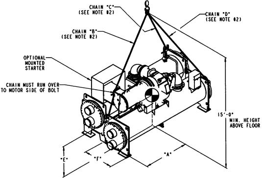
RIG MACHINE ASSEMBLY Ð See rigging instructions on label attached to machine. Also refer to rigging guide (Fig. 3 and 4), physical data in Fig. 5, and Tables 1-8B. Lift machine only from the points indicated in rigging guide. Each lifting cable or chain must be capable of supporting the entire weight of the machine.
Lifting machine from points other than those speci®ed may result in serious damage to the unit and personal injury. Rigging equipment and procedures must be adequate for machine weight. See Fig. 3 and 4 for machine weights.
NOTE: These weights are broken down into component sections for use when installing the unit in sections. For the complete machine weight, add all component sections and refrigerant charge together. See Tables 4-8B for machine component weights.
IMPORTANT: Ensure that rigging cable is over the guide bolt or cable hook on the motor end cover before lifting if cooler size is 10 through 67.
2

Fig. 1 Ð Model Number Identi®cation
3
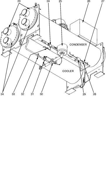
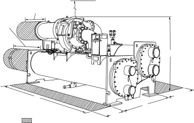
FRONT TOP VIEW
1Ð Oil Level Sight Glass
2Ð Diffuser Actuator (Hidden/19XR5 Only)
3Ð Discharge Isolation Valve
4Ð Condenser Pumpout Connection
5Ð Condenser Safety Relief Valves
6Ð Three-Way Condenser Relief Valve
7Ð Hot Gas Bypass Line
8Ð Condenser Waterbox Nozzles
9Ð Cooler Waterbox Nozzles
10Ð Cooler Safety Relief Valves
11Ð Cooler Pumpout Connection
12Ð Machine Identi®cation Nameplate
13Ð Control Panel
14Ð Refrigerant Charging Valve
15Ð Guide Vane Actuator
16Ð Compressor/Transmission
17Ð Oil Drain/Charging Valve
18Ð Oil Pump
19Ð Auxillary Power Panel
20Ð Oil Filter Isolation Valve
21Ð Oil Filter
22Ð Motor
BOTTOM REAR VIEW
23Ð Waterbox Vents
24Ð Oil Reclaim Filter
25Ð Float Chamber
26Ð Unit Mounted Starter
27Ð Refrigerant Filter/Drier Isolation Valves
28Ð Sight Glass/Moisture Indicator
29Ð Refrigerant Filter/Drier
30Ð Cooler Liquid Line Isolation Valve
31Ð Hot Gas Bypass Valve (Option)
32Ð Hot Gas Bypass Isolation Valve (Option)
33Ð Oil Reclaim Filter Isolation Valve
34Ð Waterbox Vents
Fig. 2 Ð Typical 19XR Installation
4
COMPRESSOR |
COOLER |
MAXIMUM |
VESSEL |
DIM. ``A'' |
CHAIN LENGTH |
DIM. ``E'' |
DIM. ``F'' |
|||
FRAME SIZE* |
SIZE |
WEIGHT (lb) |
LENGTH |
``B'' |
``C'' |
``D'' |
||||
|
|
|
||||||||
|
10-12 |
18,500 |
108 |
4879 |
128-79 |
138-09 |
138-09 |
28-39 |
28-69 |
|
2 |
15-17 |
19,000 |
128 |
5899 |
138-69 |
138-29 |
138-39 |
|||
|
|
|||||||||
|
20-22 |
19,500 |
108 |
4879 |
128-79 |
138-09 |
138-09 |
38-19 |
28-49 |
|
2 or 3 |
30-32 |
21,000 |
128 |
5899 |
138-69 |
138-29 |
138-39 |
38-69 |
28-69 |
|
35-37 |
22,500 |
148 |
7849 |
148-29 |
138-49 |
138-49 |
||||
|
|
|
||||||||
|
40-42 |
29,700 |
128 |
5899 |
128-89 |
128-89 |
138-49 |
|
|
|
3 |
45-47 |
31,800 |
148 |
68-109 |
138-19 |
138-29 |
138-89 |
38-29 |
28-79 |
|
50-52 |
32,200 |
128 |
5899 |
128-79 |
128-99 |
138-59 |
||||
|
|
|
||||||||
|
55-57 |
33,200 |
148 |
68-109 |
138-19 |
188-39 |
158-99 |
|
|
|
|
50-52 |
32,530 |
128 |
5899 |
138-19 |
128-99 |
138-49 |
|
|
|
4 |
55-57 |
34,230 |
148 |
6829 |
138-79 |
138-19 |
148-49 |
38-49 |
28-89 |
|
60-62 |
39,950 |
128 |
5899 |
138-19 |
128-99 |
138-49 |
||||
|
|
|
||||||||
|
65-67 |
36,950 |
148 |
6829 |
138-79 |
138-19 |
148-49 |
|
|
|
|
|
|
|
|
|
|
|
|
|
|
*The ®rst digit of the 3-digit compressor code indicates the frame size of the compressor.
MACHINE RIGGING GUIDE
NOTES:
1.Each cable must be capable of supporting the entire weight of the machine. See chart for maximum weights.
2.Chain lengths shown are typical for 158 lifting height. Some minor adjustments may be required.
Fig. 3 Ð Machine Rigging Guide (Cooler Size 10 Through 67)
5
COMPRESSOR |
COOLER |
MAXIMUM |
VESSEL |
DIM. ``A'' |
DIM. ``B'' |
DIM. ``C'' |
CHAIN LENGTH |
|||
FRAME SIZE* |
SIZE |
WEIGHT (lb) |
LENGTH |
``D'' |
``E'' |
``F'' |
||||
|
|
|
||||||||
4 |
70-72 |
40,410 |
148 |
6869 |
38-49 |
38-59 |
118-69 |
128-59 |
128-99 |
|
75-77 |
44,210 |
168 |
7859 |
38-59 |
38-59 |
128-09 |
138-39 |
138-69 |
||
|
||||||||||
|
70-72 |
45,600 |
148 |
6829 |
38-69 |
38-79 |
118-69 |
128-59 |
128-99 |
|
5 |
75-77 |
49,400 |
168 |
68-119 |
38-69 |
38-69 |
128-09 |
138-39 |
138-69 |
|
80-82 |
54,900 |
148 |
6829 |
38-69 |
38-79 |
118-69 |
128-59 |
128-99 |
||
|
||||||||||
|
85-87 |
58,300 |
168 |
68-119 |
38-69 |
38-69 |
128-09 |
138-39 |
138-69 |
|
|
|
|
|
|
|
|
|
|
|
|
*The ®rst digit of the 3-digit compressor code indicates the frame size of the compressor.
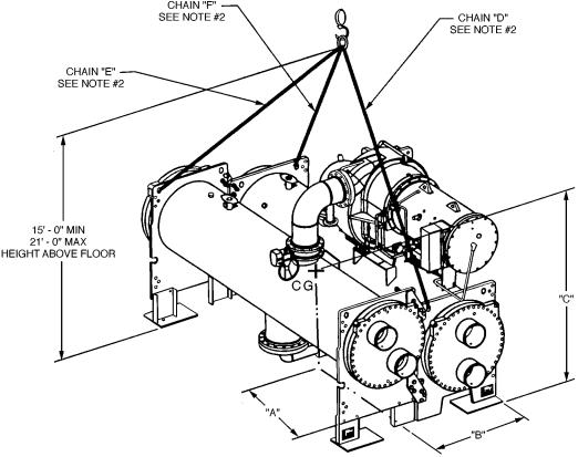
CG Ð Center of Gravity
MACHINE RIGGING GUIDE
NOTES:
1.Each chain must be capable of supporting the entire weight of the machine. See chart for maximum weights.
2.Chain lengths shown are typical for 158 lifting height. Some minor adjustments may be required.
3.Dimensions ``A'' and ``B'' de®ne distance from machine center of gravity to tube sheet outermost surfaces. Dimension ``C'' de®nes distance from machine center of gravity to ¯oor.
Fig. 4 Ð Machine Rigging Guide (Cooler Size 70 Through 87)
6
TUBE REMOVAL |
|
|
SPACE FOR |
|
|
EITHER END |
|
|
10'-0" (3048 mm) |
MOTOR SERVICE |
3'0" (915 mm) |
(SIZES 10-12, 20-22) |
||
12'-3 1/2" (3747 mm) |
CLEARANCE |
RECOMMENDED OVERHEAD |
(SIZES 15-17) |
4'0"- (1219 mm) |
SERVICE CLEARANCE |
12'-3 1/2" (3747 mm) |
|
|
(SIZES 30-32, 40-42, |
|
|
50-52, 60-62) |
|
|
14'-3" (4343 mm) |
|
|
(SIZES 35-37, 45-47, |
|
|
55-57, 65-67) |
|
|
14'-0" (4267 mm) |
|
|
(SIZES 70-72, |
|
|
80-82) |
|
|
16'-0" (4877 mm) |
|
|
(SIZES 75-77, |
|
|
85-87) |
|
|
C
|
2'-61/8" MIN |
A |
(362 mm) |
|
B |
2' MIN (610 mm)
SERVICE AREA
Fig. 5 Ð 19XR Dimensions (Refer to Tables 1 Through 3)
Table 1 Ð 19XR Dimensions (Nozzle-In-Head Waterbox)
HEAT EXCHANGER |
|
A (Length, with Nozzle-in-Head Waterbox) |
|
B (Width) |
C (Height) |
||||||
|
2-Pass* |
|
1 or 3 Pass² |
||||||||
SIZE |
|
|
|
|
|
|
|||||
|
ft-in. |
|
mm |
ft-in. |
|
mm |
ft-in. |
mm |
ft-in. |
mm |
|
10 to 12 |
11- |
37¤8 |
|
3451 |
11-103¤4 |
|
3626 |
4-113¤4 |
1518 |
6- 11¤4 |
1861 |
15 to 17 |
13- |
73¤8 |
|
4150 |
14- 21¤4 |
|
4324 |
4-113¤4 |
1518 |
6- 11¤4 |
1861 |
20 to 22 |
11- |
51¤8 |
|
3483 |
12- 01¤2 |
|
3670 |
5- 53¤4 |
1670 |
6- 31¤4 |
1911 |
30 to 32 |
13- |
81¤4 |
|
4172 |
14- 31¤4 |
|
4350 |
5- 53¤4 |
1670 |
6- 95¤8 |
2073 |
35 to 37 |
15- |
43¤4 |
|
4693 |
15-113¤4 |
|
4870 |
5- 53¤4 |
1670 |
6- 95¤8 |
2073 |
40 to 42 |
13-11 |
|
4242 |
14- 61¤4 |
|
4426 |
6- 2 |
1880 |
7- 03¤4 |
2153 |
|
45 to 47 |
15- |
71¤2 |
|
4763 |
16- 23¤4 |
|
4947 |
6- 2 |
1880 |
7- 03¤4 |
2153 |
50 to 52 |
13-111¤4 |
|
4248 |
14- 63¤4 |
|
4439 |
6- 61¤2 |
1994 |
7- 27¤8 |
2207 |
|
55 to 57 |
15- |
73¤4 |
|
4769 |
16- 31¤4 |
|
4959 |
6- 61¤2 |
1994 |
7- 27¤8 |
2207 |
60 to 62 |
13-113¤4 |
|
4261 |
14- 71¤4 |
|
4451 |
6-101¤2 |
2096 |
7- 47¤8 |
2257 |
|
65 to 67 |
15- |
81¤4 |
|
4782 |
16- 33¤4 |
|
4972 |
6-101¤2 |
2096 |
7- 47¤8 |
2257 |
70 to 72 |
16- |
4 |
|
4978 |
17- 01¤2 |
|
5194 |
7-111¤2 |
2426 |
9- 91¤2 |
2985 |
75 to 77 |
18- |
4 |
|
5588 |
19- 01¤2 |
|
5804 |
7-111¤2 |
2426 |
9- 91¤2 |
2985 |
80 to 82 |
16- |
43¤4 |
|
4997 |
17- 11¤2 |
|
5220 |
8-103¤4 |
2711 |
9-111¤4 |
3029 |
85 to 87 |
18- |
43¤4 |
|
5607 |
19- 11¤2 |
|
5829 |
8-103¤4 |
2711 |
9-111¤4 |
3029 |
*Assumes both cooler and condenser nozzles on same end of chiller.
²1 or 3 pass length applies if either (or both) cooler or condenser i s a 1 or 3 pass design.
NOTES:
1.Service access should be provided per American Society of Heating, Refrigeration, and Air Conditioning Engineers (ASHRAE) 15, latest edition, National Fire Protection Association (NFPA) 70, and local safety code.
2.Allow at least 3 ft (915 mm) overhead clearance for service rigging.
3.Certi®ed drawings available upon request.
7
Table 2 Ð 19XR Dimensions (Marine Waterbox)
|
|
|
A (Length, Marine Waterbox Ð |
|
|
||
HEAT EXCHANGER |
|
|
|
not shown) |
|
|
|
SIZE |
2-Pass* |
|
|
|
1 or 3 Pass² |
||
|
ft-in. |
|
mm |
|
ft-in. |
|
mm |
10 to 12 |
NA |
|
NA |
|
NA |
|
NA |
15 to 17 |
NA |
|
NA |
|
NA |
|
NA |
20 to 22 |
12- 65¤8 |
|
3826 |
|
14- 3 |
|
4343 |
30 to 32 |
14- 9 |
|
4496 |
|
16- 43¤4 |
|
4997 |
35 to 37 |
16- 51¤2 |
|
5017 |
|
18- 11¤4 |
|
5518 |
40 to 42 |
15- 01¤4 |
|
4591 |
|
16- 83¤4 |
|
5099 |
45 to 47 |
16- 83¤4 |
|
5099 |
|
18- 51¤4 |
|
5620 |
50 to 52 |
15- 01¤4 |
|
4591 |
|
16- 83¤4 |
|
5099 |
55 to 57 |
16- 83¤4 |
|
5099 |
|
18- 51¤4 |
|
5620 |
60 to 62 |
15- 03¤4 |
|
4591 |
|
16- 91¤4 |
|
5111 |
65 to 67 |
16- 91¤4 |
|
5112 |
|
18- 53¤4 |
|
5632 |
70 to 72 |
17- 8 |
|
5385 |
|
19-101¤2 |
|
6058 |
75 to 77 |
19- 8 |
|
5994 |
|
21-101¤2 |
|
6668 |
80 to 82 |
17- 81¤2 |
|
5398 |
|
20- 1 |
|
6121 |
85 to 87 |
19- 81¤2 |
|
6007 |
|
22- 1 |
|
6731 |
*Assumes both cooler and condenser nozzles on same end of chiller. ²1 or 3 pass length applies if cooler i s a 1 or 3 pass design.
NOTES:
1.Service access should be provided per American Society of Heating, Refrigeration, and Air Conditioning Engineers (ASHRAE) 15, latest edition, National Fire Protection Association (NFPA) 70, and local safety code.
2.Allow at least 3 ft (915 mm) overhead clearance for service rigging.
3.Certi®ed drawings available upon request.
Table 3 Ð 19XR Nozzle Size
|
|
|
NOZZLE SIZE (in.) |
|
|
|
FRAME |
|
|
(Nominal Pipe Size) |
|
|
|
SIZE |
|
Cooler |
|
|
Condenser |
|
|
1-Pass |
2-Pass |
3-Pass |
1-Pass |
2-Pass |
3-Pass |
1 |
8 |
6 |
6 |
8 |
6 |
6 |
2 |
10 |
8 |
6 |
10 |
8 |
6 |
3 |
10 |
8 |
6 |
10 |
8 |
6 |
4 |
10 |
8 |
6 |
10 |
8 |
6 |
5 |
10 |
8 |
6 |
10 |
10 |
8 |
6 |
10 |
10 |
8 |
10 |
10 |
8 |
7 |
14 |
12 |
10 |
14 |
12 |
12 |
8 |
14 |
14 |
12 |
14 |
14 |
12 |
8
Table 4 Ð 19XR Compressor Weights
|
|
ENGLISH |
|
SI |
||
MOTOR |
Total Compressor Weight* |
Total Compressor Weight* |
||||
CODE |
|
(lb) |
|
(kg) |
||
|
60 Hz |
|
50 Hz |
60 Hz |
|
50 Hz |
BD |
3,755 |
|
3,755 |
1703 |
|
1703 |
BE |
3,805 |
|
3,805 |
1726 |
|
1726 |
BF |
3,870 |
|
3,870 |
1755 |
|
1755 |
BG |
3,950 |
|
3,950 |
1792 |
|
1792 |
BH |
3,950 |
|
3,950 |
1792 |
|
1792 |
CD |
4,659 |
|
4,756 |
2134 |
|
2153 |
CE |
4,685 |
|
4,771 |
2155 |
|
2165 |
CL |
4,710 |
|
4,842 |
2137 |
|
2167 |
CM |
4,737 |
|
4,868 |
2149 |
|
2209 |
CN |
4,751 |
|
4,883 |
2156 |
|
2215 |
CP |
4,806 |
|
4,898 |
2181 |
|
2212 |
CQ |
4,874 |
|
4,898 |
2211 |
|
2212 |
DB |
6,112 |
|
6,158 |
2772 |
|
2793 |
DC |
6,138 |
|
6,224 |
2822 |
|
2823 |
DD |
6,216 |
|
6,262 |
2819 |
|
2840 |
DE |
6,224 |
|
6,351 |
2823 |
|
2881 |
DF |
6,274 |
|
6,412 |
2846 |
|
2908 |
DG |
6,364 |
|
6,466 |
2886 |
|
2933 |
DH |
6,412 |
|
6,868 |
2908 |
|
3115 |
DJ |
6,466 |
|
6,977 |
2933 |
|
3165 |
EH |
8,025 |
|
11,135 |
3640 |
|
5051 |
EJ |
11,085 |
|
11,265 |
5028 |
|
5110 |
EK |
11,160 |
|
11,282 |
5062 |
|
5118 |
EL |
11,181 |
|
11,435 |
5072 |
|
5187 |
EM |
11,271 |
|
11,435 |
5113 |
|
5187 |
EN |
11,335 |
|
11,635 |
5142 |
|
5278 |
EP |
11,434 |
|
11,605 |
5186 |
|
5264 |
|
|
|
|
|
|
|
*Compressor weight is comprised of compressor, stator, rotor, end bell, suction elbow, and discharge elbow.
NOTE: For medium voltage motors (over 600 v), add 490 lb (222 kg).
Table 5 Ð 19XR Component Weights
|
FRAME 2 |
FRAME 3 |
FRAME 4 |
FRAME 5 |
||||
COMPONENT |
COMPRESSOR |
COMPRESSOR |
COMPRESSOR |
COMPRESSOR |
||||
|
lb |
kg |
lb |
kg |
lb |
kg |
lb |
kg |
Suction Elbow |
50 |
23 |
54 |
24 |
175 |
79 |
210 |
95 |
Discharge Elbow |
60 |
27 |
46 |
21 |
157 |
71 |
140 |
63 |
Control Cabinet* |
30 |
14 |
30 |
14 |
30 |
14 |
30 |
14 |
Optional Unit-Mounted Starter² |
800 |
363 |
800 |
363 |
800 |
363 |
800 |
363 |
Optional Isolation Valves |
115 |
52 |
115 |
52 |
115 |
52 |
115 |
52 |
*Included in total cooler weight.
²Weight of optional factory-mounted starter is not included and must be added to the heat exchanger weight.
9
Table 6 Ð 19XR Heat Exchanger Data
|
|
|
ENGLISH |
|
|
|
|
|
SI |
|
|
|
|
|
Dry Rigging Weight |
|
Machine Charge |
|
Dry Rigging Weight |
|
Machine Charge |
||||||
|
|
(lb) |
|
|
|
(kg) |
|
||||||
CODE |
|
|
|
|
|
|
|
|
|
|
|
||
Cooler |
Condenser |
Refrigerant |
Water Volume |
Cooler |
Condenser |
Refrigerant |
|
Water |
|||||
|
|
||||||||||||
|
Weight |
|
(gal) |
Weight |
Volume |
||||||||
|
Only |
Only |
|
Only |
Only |
||||||||
|
Cooler |
Condenser |
Cooler |
Condenser |
Cooler |
Condenser |
Cooler |
|
Condenser |
||||
|
|
|
|
|
|
||||||||
10 |
2,742 |
2,704 |
290 |
200 |
34 |
42 |
1244 |
1227 |
132 |
91 |
129 |
|
158 |
11 |
2,812 |
2,772 |
310 |
200 |
37 |
45 |
1276 |
1257 |
141 |
91 |
140 |
|
170 |
12 |
2,883 |
2,857 |
330 |
200 |
40 |
49 |
1308 |
1296 |
150 |
91 |
152 |
|
185 |
15 |
3,003 |
2,984 |
320 |
250 |
39 |
48 |
1362 |
1354 |
145 |
113 |
149 |
|
183 |
16 |
3,089 |
3,068 |
340 |
250 |
43 |
52 |
1401 |
1392 |
154 |
113 |
163 |
|
198 |
17 |
3,176 |
3,173 |
370 |
250 |
47 |
57 |
1441 |
1439 |
168 |
113 |
178 |
|
216 |
20 |
3,442 |
3,523 |
345 |
225 |
48 |
48 |
1561 |
1598 |
156 |
102 |
183 |
|
181 |
21 |
3,590 |
3,690 |
385 |
225 |
55 |
55 |
1628 |
1674 |
175 |
102 |
207 |
|
210 |
22 |
3,746 |
3,854 |
435 |
225 |
62 |
63 |
1699 |
1748 |
197 |
102 |
234 |
|
239 |
30 |
4,137 |
3,694 |
350 |
260 |
55 |
55 |
1877 |
1676 |
159 |
118 |
208 |
|
210 |
31 |
4,319 |
3,899 |
420 |
260 |
64 |
65 |
1959 |
1769 |
190 |
118 |
242 |
|
246 |
32 |
4,511 |
4,100 |
490 |
260 |
72 |
74 |
2046 |
1860 |
222 |
118 |
271 |
|
282 |
35 |
4,409 |
4,606 |
400 |
310 |
61 |
62 |
2000 |
2089 |
181 |
141 |
232 |
|
233 |
36 |
4,617 |
4,840 |
480 |
310 |
70 |
72 |
2094 |
2195 |
218 |
141 |
266 |
|
273 |
37 |
4,835 |
5,069 |
550 |
310 |
80 |
83 |
2193 |
2299 |
249 |
141 |
301 |
|
314 |
40 |
5,898 |
6,054 |
560 |
280 |
89 |
96 |
2675 |
2746 |
254 |
127 |
338 |
|
365 |
41 |
6,080 |
6,259 |
630 |
280 |
97 |
106 |
2757 |
2839 |
286 |
127 |
368 |
|
400 |
42 |
6,244 |
6,465 |
690 |
280 |
105 |
114 |
2832 |
2933 |
313 |
127 |
396 |
|
433 |
45 |
6,353 |
6,617 |
640 |
330 |
98 |
106 |
2881 |
3001 |
290 |
150 |
372 |
|
403 |
46 |
6,561 |
6,851 |
720 |
330 |
108 |
117 |
2976 |
3108 |
327 |
150 |
407 |
|
442 |
47 |
6,748 |
7,085 |
790 |
330 |
116 |
127 |
3060 |
3214 |
358 |
150 |
438 |
|
481 |
50 |
7,015 |
7,285 |
750 |
400 |
115 |
128 |
3181 |
3304 |
340 |
181 |
435 |
|
483 |
51 |
7,262 |
7,490 |
840 |
400 |
126 |
137 |
3293 |
3397 |
381 |
181 |
477 |
|
518 |
52 |
7,417 |
7,683 |
900 |
400 |
133 |
136 |
3364 |
3484 |
408 |
181 |
502 |
|
552 |
55 |
7,559 |
7,990 |
870 |
490 |
127 |
142 |
3428 |
3624 |
395 |
222 |
481 |
|
536 |
56 |
7,839 |
8,214 |
940 |
490 |
139 |
152 |
3555 |
3725 |
426 |
222 |
527 |
|
575 |
57 |
8,016 |
8,434 |
980 |
490 |
147 |
162 |
3635 |
3825 |
445 |
222 |
557 |
|
613 |
60 |
8,270 |
8,286 |
940 |
420 |
144 |
159 |
3751 |
3758 |
426 |
190 |
546 |
|
601 |
61 |
8,462 |
8,483 |
980 |
420 |
153 |
168 |
3838 |
3847 |
445 |
190 |
578 |
|
636 |
62 |
8,617 |
8,676 |
1020 |
420 |
160 |
177 |
3908 |
3935 |
463 |
190 |
604 |
|
669 |
65 |
8,943 |
9,204 |
1020 |
510 |
160 |
176 |
4056 |
4174 |
463 |
231 |
605 |
|
668 |
66 |
9,161 |
9,428 |
1060 |
510 |
169 |
187 |
4155 |
4276 |
481 |
231 |
641 |
|
707 |
67 |
9,338 |
9,648 |
1090 |
510 |
177 |
197 |
4235 |
4376 |
494 |
231 |
671 |
|
745 |
70 |
12,395 |
13,139 |
1220 |
780 |
224 |
209 |
5622 |
5960 |
553 |
354 |
848 |
|
791 |
71 |
12,821 |
13,568 |
1340 |
780 |
243 |
229 |
5816 |
6154 |
608 |
354 |
919 |
|
867 |
72 |
13,153 |
13,969 |
1440 |
780 |
257 |
248 |
5966 |
6336 |
653 |
354 |
974 |
|
937 |
75 |
13,293 |
14,211 |
1365 |
925 |
245 |
234 |
6030 |
6446 |
619 |
420 |
927 |
|
885 |
76 |
13,780 |
14,702 |
1505 |
925 |
266 |
257 |
6251 |
6669 |
683 |
420 |
1009 |
|
971 |
77 |
14,159 |
15,160 |
1625 |
925 |
283 |
278 |
6423 |
6877 |
737 |
420 |
1072 |
|
1052 |
80 |
16,156 |
15,746 |
1500 |
720 |
285 |
264 |
7328 |
7142 |
680 |
327 |
1080 |
|
1000 |
81 |
16,530 |
16,176 |
1620 |
720 |
302 |
284 |
7498 |
7337 |
735 |
327 |
1143 |
|
1075 |
82 |
16,919 |
16,606 |
1730 |
720 |
319 |
304 |
7674 |
7532 |
785 |
327 |
1208 |
|
1150 |
85 |
17,296 |
17,001 |
1690 |
860 |
313 |
295 |
7845 |
7712 |
767 |
390 |
1183 |
|
1118 |
86 |
17,723 |
17,492 |
1820 |
860 |
331 |
318 |
8039 |
7934 |
826 |
390 |
1254 |
|
1205 |
87 |
18,169 |
17,984 |
1940 |
860 |
351 |
341 |
8241 |
8158 |
880 |
390 |
1329 |
|
1291 |
|
|
|
|
|
|
|
|
|
|
|
|
|
|
*Rigging weights are for standard tubes of standard wall thickness (Turbo-B3 and Spike®n 2, 0.025-in. [0.635 mm] wall).
NOTES:
1.Cooler includes the control panel (LID), suction elbow, and 1¤2 the distribution piping weight.
2.Condenser includes ¯oat valve and sump, discharge elbow, and 1¤2 the distribution piping weight.
3.For special tubes refer to the 19XR Computer Selection Program.
4.All weights for standard 2 pass NIH (nozzle-in-head) design.
10
Table 7 Ð 19XR Additional Data for Marine Waterboxes*
HEAT EXCHANGER |
|
ENGLISH |
|
|
SI |
|
|
FRAME, PASS |
Psig |
Rigging Weight |
Water Volume |
kPa |
Rigging Weight |
Water Volume |
|
(lb) |
(gal) |
(kg) |
(L) |
||||
|
|
|
|||||
FRAME 2, 1 AND 2 PASS |
150 |
730 |
84 |
1034 |
331 |
318 |
|
FRAME 2, 2 PASS |
150 |
365 |
42 |
1034 |
166 |
159 |
|
FRAME 3, 1 AND 2 PASS |
150 |
730 |
84 |
1034 |
331 |
317 |
|
FRAME 3, 2 PASS |
150 |
365 |
42 |
1034 |
166 |
159 |
|
FRAME 4, 1 AND 3 PASS |
150 |
1060 |
123 |
1034 |
481 |
465 |
|
FRAME 4, 2 PASS |
150 |
530 |
61 |
1034 |
240 |
231 |
|
FRAME 5, 1 AND 3 PASS |
150 |
1240 |
139 |
1034 |
562 |
526 |
|
FRAME 5, 2 PASS |
150 |
620 |
69 |
1034 |
281 |
263 |
|
FRAME 6, 1 AND 3 PASS |
150 |
1500 |
162 |
1034 |
680 |
612 |
|
FRAME 6, 2 PASS |
150 |
750 |
81 |
1034 |
340 |
306 |
|
FRAME 7, 1 AND 3 PASS |
150 |
2010 |
326 |
1034 |
912 |
1234 |
|
FRAME 7, 2 PASS |
150 |
740 |
163 |
1034 |
336 |
617 |
|
FRAME 8, 1 AND 3 PASS |
150 |
1855 |
406 |
1034 |
841 |
1537 |
|
FRAME 8, 2 PASS |
150 |
585 |
203 |
1034 |
265 |
768 |
|
FRAME 2, 1 AND 3 PASS |
300 |
860 |
84 |
2068 |
390 |
318 |
|
FRAME 2, 2 PASS |
300 |
430 |
42 |
2068 |
195 |
159 |
|
FRAME 3, 1 AND 3 PASS |
300 |
860 |
84 |
2068 |
390 |
317 |
|
FRAME 3, 2 PASS |
300 |
430 |
42 |
2068 |
195 |
159 |
|
FRAME 4, 1 AND 3 PASS |
300 |
1210 |
123 |
2068 |
549 |
465 |
|
FRAME 4, 2 PASS |
300 |
600 |
61 |
2068 |
272 |
231 |
|
FRAME 5, 1 AND 3 PASS |
300 |
1380 |
139 |
2068 |
626 |
526 |
|
FRAME 5, 2 PASS |
300 |
690 |
69 |
2068 |
313 |
263 |
|
FRAME 6, 1 AND 3 PASS |
300 |
1650 |
162 |
2068 |
748 |
612 |
|
FRAME 6, 2 PASS |
300 |
825 |
81 |
2068 |
374 |
306 |
|
FRAME 7, 1 AND 3 PASS |
300 |
3100 |
326 |
2068 |
1406 |
1234 |
|
FRAME 7, 2 PASS |
300 |
2295 |
163 |
2068 |
1041 |
617 |
|
FRAME 8, 1 AND 3 PASS |
300 |
2745 |
405 |
2068 |
1245 |
1533 |
|
FRAME 8, 2 PASS |
300 |
1630 |
203 |
2068 |
739 |
768 |
|
|
|
|
|
|
|
|
*Add to heat exchanger data for total weights or volumes.
NOTES:
1.Weight adder shown is the same for cooler and condenser of equal frame size.
2.For the total weight of a vessel with a marine waterbox, add these values to the heat exchanger weights (or volumes).
11
Table 8A Ð 19XR Waterbox Cover Weights
ENGLISH (lb)
HEAT |
WATERBOX |
FRAME 1 |
FRAME 2 |
|
|
FRAME 3 |
||||||
EXCHANGER |
DESCRIPTION |
Standard |
Flanged |
Standard |
Flanged |
|
Standard |
Flanged |
||||
Nozzles |
Nozzles |
|
Nozzles |
|||||||||
|
|
|
|
|
|
|
|
|||||
|
NIH, 1 Pass Cover, 150 psig |
177 |
|
204 |
|
320 |
|
|
350 |
320 |
350 |
|
|
NIH, 2 Pass Cover, 150 psig |
185 |
|
218 |
|
320 |
|
|
350 |
320 |
350 |
|
|
NIH, 3 Pass Cover, 150 psig |
180 |
|
196 |
|
300 |
|
|
340 |
300 |
340 |
|
COOLER/ |
NIH/MWB End Cover, 150 psig |
136 |
|
136 |
|
300 |
|
|
300 |
300 |
300 |
|
CONDENSER |
NIH, 1 Pass Cover, 300 psig |
248 |
|
301 |
|
411 |
|
|
486 |
411 |
486 |
|
|
NIH, 2 Pass Cover, 300 psig |
255 |
|
324 |
|
411 |
|
|
518 |
411 |
518 |
|
|
NIH, 3 Pass Cover, 300 psig |
253 |
|
288 |
|
433 |
|
|
468 |
433 |
468 |
|
|
NIH/MWB End Cover, 300 psig |
175 |
|
175 |
|
400 |
|
|
400 |
400 |
400 |
|
|
|
|
|
|
|
|
|
|
|
|
|
|
|
|
|
|
|
|
|
|
|
|
|||
HEAT |
WATERBOX |
FRAME 4 |
FRAME 5 |
|
|
FRAME 6 |
||||||
EXCHANGER |
DESCRIPTION |
Standard |
Flanged |
Standard |
Flanged |
|
Standard |
Flanged |
||||
Nozzles |
Nozzles |
|
Nozzles |
|||||||||
|
|
|
|
|
|
|
|
|||||
|
NIH, 1 Pass Cover, 150 psig |
485 |
|
521 |
|
616 |
|
|
652 |
802 |
838 |
|
|
NIH, 2 Pass Cover, 150 psig |
487 |
|
540 |
|
590 |
|
|
663 |
770 |
843 |
|
|
NIH, 3 Pass Cover, 150 psig |
504 |
|
520 |
|
629 |
|
|
655 |
817 |
843 |
|
COOLER/ |
NIH/MWB End Cover, 150 psig |
379 |
|
379 |
|
428 |
|
|
428 |
583 |
583 |
|
CONDENSER |
NIH, 1 Pass Cover, 300 psig |
593 |
|
668 |
|
764 |
|
|
655 |
880 |
956 |
|
|
NIH, 2 Pass Cover, 300 psig |
594 |
|
700 |
|
761 |
|
|
839 |
844 |
995 |
|
|
NIH, 3 Pass Cover, 300 psig |
621 |
|
656 |
|
795 |
|
|
838 |
901 |
952 |
|
|
NIH/MWB End Cover, 300 psig |
569 |
|
569 |
|
713 |
|
|
713 |
833 |
833 |
|
|
|
|
|
|
|
|
|
|
|
|
|
|
|
|
|
|
|
|
|
|
|
|
|||
HEAT |
WATERBOX |
FRAME 7 COOLER |
|
FRAME 7 CONDENSER |
|
|
|
|||||
EXCHANGER |
DESCRIPTION |
Standard |
|
Flanged |
|
Standard |
|
Flanged |
|
|
|
|
Nozzles |
|
|
Nozzles |
|
|
|
|
|||||
|
|
|
|
|
|
|
|
|
|
|
||
|
NIH, 1 Pass Cover, 150 psig |
1392 |
|
1469 |
|
1205 |
|
|
1282 |
|
|
|
|
NIH, 2 Pass Cover, 150 psig |
1345 |
|
1461 |
|
1163 |
|
|
1279 |
|
|
|
|
NIH, 3 Pass Cover, 150 psig |
1434 |
|
1471 |
|
1222 |
|
|
1280 |
|
|
|
COOLER/ |
NIH/MWB End Cover, 150 psig |
1022 |
|
1022 |
|
920 |
|
|
920 |
|
|
|
CONDENSER |
NIH, 1 Pass Cover, 300 psig |
1985 |
|
2150 |
|
1690 |
|
|
1851 |
|
|
|
|
NIH, 2 Pass Cover, 300 psig |
1934 |
|
2174 |
|
1628 |
|
|
1862 |
|
|
|
|
NIH, 3 Pass Cover, 300 psig |
2009 |
|
2090 |
|
1714 |
|
|
1831 |
|
|
|
|
NIH/MWB End Cover, 300 psig |
1567 |
|
1567 |
|
1923 |
|
|
1923 |
|
|
|
|
|
|
|
|
|
|
|
|
|
|||
|
|
|
|
|
|
|
||||||
HEAT |
WATERBOX |
FRAME 8 COOLER |
|
FRAME 8 CONDENSER |
|
|
|
|||||
EXCHANGER |
DESCRIPTION |
Standard |
|
Flanged |
|
Standard |
|
Flanged |
|
|
|
|
Nozzles |
|
|
Nozzles |
|
|
|
|
|||||
|
|
|
|
|
|
|
|
|
|
|
||
|
NIH, 1 Pass Cover, 150 psig |
1831 |
|
1909 |
|
1682 |
|
|
1760 |
|
|
|
|
NIH, 2 Pass Cover, 150 psig |
1739 |
|
1893 |
|
1589 |
|
|
1744 |
|
|
|
|
NIH, 3 Pass Cover, 150 psig |
1851 |
|
1909 |
|
1702 |
|
|
1761 |
|
|
|
COOLER/ |
NIH/MWB End Cover, 150 psig |
1480 |
|
1480 |
|
1228 |
|
|
1228 |
|
|
|
CONDENSER |
NIH, 1 Pass Cover, 300 psig |
2690 |
|
2854 |
|
2394 |
|
|
2549 |
|
|
|
|
NIH, 2 Pass Cover, 300 psig |
2595 |
|
2924 |
|
2269 |
|
|
2578 |
|
|
|
|
NIH, 3 Pass Cover, 300 psig |
2698 |
|
2861 |
|
2417 |
|
|
2529 |
|
|
|
|
NIH/MWB End Cover, 300 psig |
1440 |
|
1440 |
|
1767 |
|
|
1767 |
|
|
|
|
|
|
|
|
|
|
|
|
|
|
|
|
LEGEND |
|
|
|
|
|
|
|
|
|
|
|
|
NIH Ð Nozzle-in-Head
MWB Ð Marine Waterbox
NOTE: Weight for NIH 2-Pass Cover, 150 psig is included in the heat exchanger weights shown in Table 6.
RIG MACHINE COMPONENTS Ð Refer to instructions below, Fig. 6-9, and Carrier Certi®ed Prints for machine component disassembly.
IMPORTANT: Only a quali®ed service technician should perform this operation.
Do not attempt to disconnect ¯anges while the machine is under pressure. Failure to relieve pressure can result in personal injury or damage to the unit.
Before rigging the compressor, disconnect all wires entering the power panel.
12
 Loading...