


GEMINI™ SELECT
38APS025-050,38APD025-100 Air-Cooled Condensing Units
with PURON® Refrigerant (R-410A)
50/60 Hz
Installation Instructions
CONTENTS
Page
SAFETY CONSIDERATIONS . . . . . . . . . . . . . . . . . . . . . . 1
INSTALLATION . . . . . . . . . . . . . . . . . . . . . . . . . . . . . . . . 1-34
Step 1 — Inspect Shipment . . . . . . . . . . . . . . . . . . . . . . 1
Step 2 — Rig and Place Unit . . . . . . . . . . . . . . . . . . . . . 1
•DOMESTIC UNITS
•EXPORT UNITS
•PLACING UNITS
Step 3 — Make Refrigerant Piping
Connections . . . . . . . . . . . . . . . . . . . . . . . . . . . . . . . . . . 17
•SIZE REFRIGERANT LINES
•LIQUID LINE SOLENOID VALVE
•THERMOSTATIC EXPANSION VALVES
•LIQUID LINE FILTER DRIER
•LONG LINE APPLICATIONS
•HOT GAS BYPASS
•FINAL CONNECTION AND LEAK TEST
•EVACUATION AND DEHYDRATION
Step 4 — Make Electrical Connections . . . . . . . . . . 26
•POWER SUPPLY
•POWER WIRING
•CONTROL POWER
•FIELD CONTROL WIRING
Step 5 — Install Accessories . . . . . . . . . . . . . . . . . . . . 34
•LOW-AMBIENT OPERATION
•MISCELLANEOUS ACCESSORIES
SAFETY CONSIDERATIONS
Installing, starting up, and servicing this equipment can be hazardous due to system pressures, electrical components, and equipment location (roofs, elevated structures, etc.).
Only trained, qualified installers and service mechanics should install, start up, and service this equipment.
Untrained personnel can perform basic maintenance functions, such as cleaning coils. All other operations should be performed by trained service personnel.
When working on the equipment, observe precautions in the literature, and on tags, stickers, and labels attached to the equipment and any other safety precautions that may apply.
•Follow all safety codes.
•Wear safety glasses and work gloves.
•Use care in handling, rigging, and setting bulky equipment.
 WARNING
Open all remote disconnects before servicing this equipment. Failure to do so could result in personal injury from electric shock.
 CAUTION
Puron refrigerant (R-410A) systems operate at higher pressures than standard R-22 systems. Do not use R-22 service equipment or components on Puron refrigerant equipment. If service equipment is not rated for Puron refrigerant, equipment damage or personal injury may result.
INSTALLATION
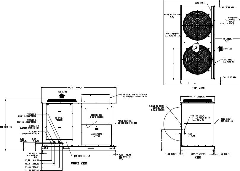
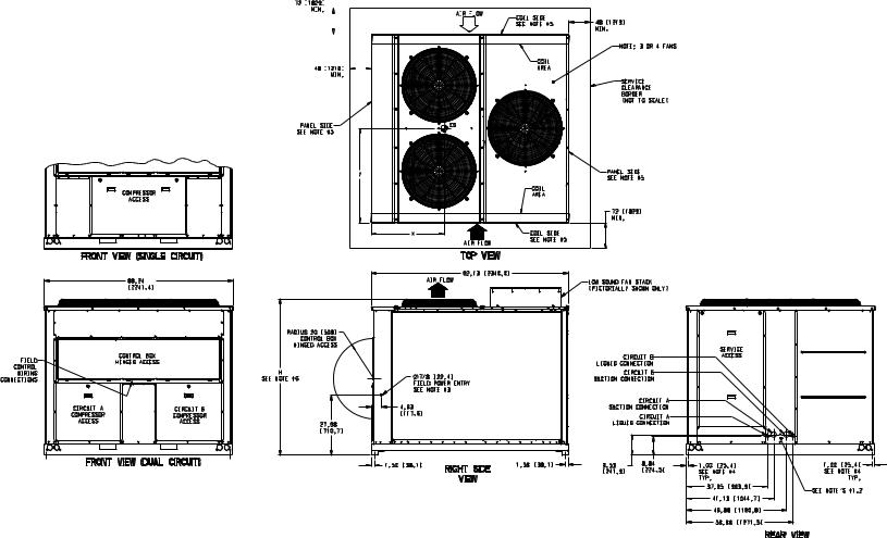
Step 1 — Inspect Shipment — Inspect unit for damage upon arrival. If damage is found, immediately file a claim with the shipping company. Verify proper unit delivery by checking unit nameplate data and the model number nomenclature shown in Fig. 1. See Tables 1-4 for unit physical data.
Step 2 — Rig and Place Unit — All units are designed for overhead rigging, and it is important that this method be used. Lifting holes are provided in the frame base rails. It is recommended to use shackles in the lifting holes (see rigging label on the unit and Table 5, and Fig. 2 and 3 for rigging weights and center of gravity). All panels must be in place when rigging.
IMPORTANT: To maintain unit stability while lifting, use 4 cables, chains or straps of equal length. Attach one end of each cable to shackle attachment point and the other end of each cable to the overhead rigging point.
Use spreader bars or frame to keep the cables, chains, and straps clear of the unit sides. Leave standard coil protection packaging in place during rigging to provide protection to coils. Remove and discard all coil protection after rigging cables are detached.
 CAUTION
All panels must be in place when rigging. Failure to comply could result in equipment damage.
 CAUTION
For unit sizes 025 to 060 when handling with a forklift, handle only through fork pocket holes. Failure to follow this caution could result in equipment damage or personal injury.
 CAUTION
For unit sizes 070 to 100, do not forklift the unit unless unit is attached to a skid designed for forklifting. Failure to follow this caution could result in equipment damage or personal injury.
Manufacturer reserves the right to discontinue, or change at any time, specifications or designs without notice and without incurring obligations.
Catalog No. 04-53380002-01 |
Printed in U.S.A. |
Form 38AP-1SI |
Pg 1 |
8-09 |
Replaces: New |
DOMESTIC UNITS — Standard 38AP unit packaging consists of coil protection only. Skids are not provided. If overhead rigging is not available at the jobsite, place the unit on a skid or pad before dragging or rolling. When rolling, use a minimum of 3 rollers. When dragging, pull the pad or skid. Do not apply force to the unit. When in final position, raise from above to lift unit off the pad or skid.
EXPORT UNITS — All export units are mounted on skids with vertical coil protection. Leave the unit on the skid until it is in final position. While on the skid, the unit can be rolled or skidded. Apply force to the skid, not to the unit. Use a minimum of 3 rollers when rolling. When in final position, raise from above to remove the skid.
PLACING UNITS — When considering location of the unit, be sure to consult National Electrical Code (NEC, U.S.A.) and local code requirements. Allow sufficient space for airflow, wiring, piping, and service. The placement area must be level and strong enough to support the operating weight of the unit. (See Table 5.) When unit is in proper location, use of mounting holes in base rails is recommended for securing unit to supporting structure. For mounting unit on vibration isolators,
4 x 24 in. perimeter support ASTM “C” channels between unit and the isolators are recommended with a minimum of 4 channels per unit. Fasteners for mounting unit are field supplied. See Fig. 4.
Refer to Fig. 5-8 for airflow clearances. Recommended minimum clearances are 6 ft (1829 mm) for unrestricted airflow and service on sides of unit, 4 ft (1219 mm) on ends, and unrestricted clear air space above the unit. Provide ample space to connect liquid and suction lines to indoor unit. For multiple units, allow 10 ft (3048 mm) separation between airflow surfaces. If walls surround the unit, wall height should not exceed the top of the unit fan discharge. Installation in a pit is not recommended.
IMPORTANT: Be sure to mount unit level to ensure proper oil return to compressors.
Refer to Fig. 9 for outdoor fan and compressor layout.
Refer to Fig. 10 and 11 for unit piping installation. See Table 6 for refrigerant specialties part numbers.
38AP D 025 6 4 A 1 0 0 5 0
38AP – Split System Condensing Unit
Refrigeration Circuit Options*
D – Dual Refrigeration Circuit
S – Single Refrigeration Circuit
Nominal Capacity – Tons (kW) |
|
|
|
|
||||||
025 |
– |
25 |
(88) |
050 |
– |
50 (176) |
090 |
– |
90 |
(317) |
027 |
– |
27 |
(95) |
060 |
– |
60 (211) |
100 |
– |
100 |
(352) |
030 |
– |
30 (106) |
070 |
– |
70 (246) |
|
|
|
|
|
040 |
– |
40 (141) |
080 |
– |
80 (281) |
|
|
|
|
|
Power Supply 1 – 575-3-60 2 – 380-3-60
5– 280/230-3-60
6– 460-3-60
9 – 380/415-3-50
Condenser Coil/Low Sound Options
4– MCHX, No Sound Treatment
5– E-coat, MCHX, No Sound Treatment C – MCHX, Low Sound Fan(s)
D – E-coat MCHX, Low Sound Fan(s)
H – MCHX, Low Sound Fan(s), Compressor Blankets
J – E-coat MCHX, Low Sound Fan(s), Compressor Blankets
Revision Level |
a38-7100.eps |
A – Current Revision Level |
|
LEGEND
EMM — Energy Management Module
MCHX — Microchannel Heat Exchanger
*38APS units available in sizes 025-050 only.
Packaging/Security Options
0 – Std Packaging
8 – Std Packaging, Bottom Skid
J – Bottom Skid, Top Crate, Bag
Controls/Communications Options
2 |
– |
Scrolling Marquee |
3 |
– |
EMM, Scrolling Marquee |
5 |
– |
No Display |
Electrical Options
0– Single Point Power, Terminal Block
1– Single Point Power,
Non-Fused Disconnect
Ambient/Capacity Control/
Interrupt Options
0– Std Ambient, Std Compressor, Std Interrupt
2– Std Ambient, Digital Compressor, Std Interrupt
3– Std Ambient, Std Compressor, High Interrupt
5– Std Ambient, Digital Compressor, High Interrupt
6– Low Ambient, Std Compressor, Std Interrupt
8– Low Ambient, Digital Compressor, Std Interrupt
9– Low Ambient, Std Compressor, High Interrupt
C– Low Ambient, Digital Compressor, High Interrupt
Line Length Options
1– Standard Line Length
2– Long Line Length Check Valves
Fig. 1 — Model Number Nomenclature
2
Table 1 — 38AP025-050 Unit Physical Data — English
|
|
38AP UNIT SIZE |
025 |
|
|
027 |
|
|
030 |
|
040 |
|
|
|
|
|
050 |
|
|
|
|||||
NOMINAL CAPACITY, 50/60Hz (tons) |
21/25 |
|
23/27 |
|
|
25/30 |
|
33/40 |
|
|
|
42/50 |
|
||||||||||||
CIRCUIT |
|
Dual |
|
Single |
|
Dual |
|
|
Single |
|
Dual |
|
Single |
|
Dual |
|
|
Single |
|
|
Dual |
|
|
Single |
|
OPERATING WEIGHTS (lb) |
|
|
|
|
|
|
|
|
|
|
|
|
|
|
|
|
|
|
|
|
|
|
|
||
Standard |
|
1095 |
|
1077 |
|
1258 |
|
|
1240 |
|
1264 |
|
1246 |
|
2094 |
|
|
1968 |
|
|
2120 |
|
|
1977 |
|
|
|
|
|
|
|
|
|
|
|
||||||||||||||||
With Low Sound Option |
1131 |
|
1113 |
|
1294 |
|
|
1276 |
|
1300 |
|
1282 |
|
2148 |
|
|
2022 |
|
|
2174 |
|
|
2031 |
||
APPROXIMATE REFRIGERANT CHARGE, |
28 |
|
24 |
|
30 |
|
|
26 |
|
30 |
|
26 |
|
52 |
|
|
40 |
|
|
52 |
|
|
40 |
||
TYPICAL (lb)* |
|
|
|
|
|
|
|
|
|
|
|
|
|
|
|
|
|
|
|
|
|
|
|
||
NITROGEN SHIPPING CHARGE |
|
|
|
|
|
|
|
|
|
15 psig |
|
|
|
|
|
|
|
|
|
|
|
||||
COMPRESSOR |
11 (2) |
|
11 (2) |
|
13 (2) |
|
|
13 (2) |
|
15 (2) |
|
15 (2) |
|
10 (2)/ |
|
|
13 (3) |
|
|
11 (2)/ |
|
|
15 (3) |
||
hp (Qty) (CKT A/CKT B) |
|
|
|
|
|
|
|
|
|
|
|
|
|
8.5 (2) |
|
|
|
|
|
13 (2) |
|
|
|
||
CAPACITY STEPS |
|
|
|
|
|
|
|
|
|
|
|
|
|
|
|
|
|
|
|
|
|
|
|
||
Standard |
|
2 |
|
2 |
|
2 |
|
|
2 |
|
2 |
|
2 |
|
4 |
|
|
3 |
|
|
4 |
|
|
3 |
|
|
|
|
|
|
|
|
|
|
|
||||||||||||||||
Digital Option |
22 |
|
22 |
|
22 |
|
|
22 |
|
22 |
|
22 |
|
44 |
|
|
33 |
|
|
44 |
|
|
33 |
||
CRANKCASE HEATER (W) (each compressor) |
|
|
|
|
|
|
|
|
|
|
90 |
|
|
|
|
|
|
|
|
|
|
|
|||
CONDENSER FANS |
|
|
|
|
|
|
|
|
|
|
|
|
|
|
|
|
|
|
|
|
|
|
|
||
Standard |
|
|
|
|
|
|
|
|
|
|
Propeller Type - Direct Drive |
|
|
|
|
|
|
|
|||||||
Quantity |
|
2 |
|
2 |
|
2 |
|
|
2 |
|
2 |
|
2 |
|
3 |
|
|
3 |
|
|
3 |
|
|
3 |
|
RPM |
|
|
|
|
|
|
|
|
|
|
|
1140 (60 Hz), 950 (50 Hz) |
|
|
|
|
|
|
|
||||||
Diameter (in.) |
|
|
|
|
|
|
|
|
|
|
30 |
|
|
|
|
|
|
|
|
|
|
|
|||
Total Watts (60 Hz) |
3300 |
|
3300 |
|
3300 |
|
|
3300 |
|
3300 |
|
3300 |
|
4200 |
|
|
4200 |
|
|
4200 |
|
|
4200 |
||
Total Watts (50 Hz) |
2750 |
|
2750 |
|
2750 |
|
|
2750 |
|
2750 |
|
2750 |
|
3500 |
|
|
3500 |
|
|
3500 |
|
|
3500 |
||
Low Noise |
|
|
|
|
|
|
|
|
Shrouded Axial Fan - Direct Drive |
|
|
|
|
|
|
|
|||||||||
Quantity |
|
2 |
|
2 |
|
2 |
|
|
2 |
|
2 |
|
2 |
|
3 |
|
|
3 |
|
|
3 |
|
|
3 |
|
RPM |
|
|
|
|
|
|
|
|
|
|
|
850 (60 Hz), 700 (50 Hz) |
|
|
|
|
|
|
|
||||||
Diameter (in.) |
|
|
|
|
|
|
|
|
|
|
30 |
|
|
|
|
|
|
|
|
|
|
|
|||
Total Watts (60 Hz) |
2750 |
|
2750 |
|
2750 |
|
|
2750 |
|
2750 |
|
2750 |
|
3500 |
|
|
3500 |
|
|
3500 |
|
|
3500 |
||
Total Watts (50 Hz) |
2300 |
|
2300 |
|
2300 |
|
|
2300 |
|
2300 |
|
2300 |
|
2900 |
|
|
2900 |
|
|
2900 |
|
|
2900 |
||
CONDENSER COIL |
|
|
|
|
|
|
|
|
|
MCHX Type |
|
|
|
|
|
|
|
|
|
|
|
||||
No. Coils per Circuit |
|
|
|
1 |
|
|
|
|
|
|
|
|
|
|
1 |
|
|
|
|||||||
|
|
|
|
|
|
|
|
|
|
|
|
|
|
||||||||||||
sq ft |
|
|
27.1 |
|
27.1 |
|
33.9 |
|
|
33.9 |
|
33.9 |
|
33.9 |
|
67.8 |
|
|
67.8 |
|
|
67.8 |
|
|
67.8 |
TEMPERATURE RELIEF |
|
|
|
|
Fusible Plug on Liquid Lines of Each Circuit - 210 F |
|
|
|
|
|
|
||||||||||||||
CONNECTIONS (in.) ODF (CKT A/CKT B) |
|
|
|
|
|
|
|
|
|
|
|
|
|
|
|
|
|
|
|
|
|
|
|
||
Suction Line |
13/8 / 13/8 |
|
15/8 |
|
13/8 / 13/8 |
|
|
15/8 |
|
13/8 / 13/8 |
|
15/8 |
|
15/8 / 15/8 |
|
|
21/8 |
|
|
15/8 / 15/8 |
|
|
21/8 |
||
|
|
|
|
|
|
|
|
|
|||||||||||||||||
Liquid Line |
5/8 / 5/8 |
|
5/8 |
|
5/8 / 5/8 |
|
|
5/8 |
|
5/8 / 5/8 |
|
7/8 |
|
5/8 / 5/8 |
|
|
7/8 |
|
|
5/8 / 5/8 |
|
|
7/8 |
||
MAXIMUM HEIGHT FOR 3° F SUBCOOLING |
75 |
|
75 |
|
75 |
|
|
75 |
|
75 |
|
75 |
|
75 |
|
|
75 |
|
|
75 |
|
|
75 |
||
(ft)† |
|
|
|
|
|
|
|
|
|
|
|
|
|
|
|
|
|
|
|
|
|
|
|
|
|
CAPACITY PER CIRCUIT (%) (CKT A/CKT B) |
50/50 |
|
100 |
|
50/50 |
|
|
100 |
|
50/50 |
|
100 |
|
54/46 |
|
|
100 |
|
|
48/52 |
|
|
100 |
||
MINIMUM UNIT CAPACITY (%) |
50 |
|
50 |
|
50 |
|
|
50 |
|
50 |
|
50 |
|
23 |
|
|
33 |
|
|
23 |
|
|
33 |
||
|
|
LEGEND |
|
|
|
|
|
|
|
|
|
|
|
|
|
|
|
|
|
|
|
|
|
|
|
MCHX |
— |
Microchannel Heat Exchanger |
|
|
|
|
|
|
|
|
|
|
|
|
|
|
|
|
|
|
|
|
|
|
|
ODF |
— |
Outside Diameter, Female |
|
|
|
|
|
|
|
|
|
|
|
|
|
|
|
|
|
|
|
|
|
|
|
*Typical operating charge with 25 ft of interconnecting piping. Operating charge is approximate for maximum system capacity. Unit is factory supplied with nitrogen holding charge. Refrigerant charge for dual circuit units is the total for both circuits.
†Maximum vertical separation between evaporator coil and condensing unit if condensing unit is below the evaporator.
3
Table 2 — 38AP060-100 Unit Physical Data — English
|
|
38AP UNIT SIZE |
060 |
|
070 |
|
|
080 |
|
|
090 |
|
100 |
NOMINAL CAPACITY, 50/60Hz (tons) |
50/60 |
|
58/70 |
|
|
67/80 |
|
|
75/90 |
|
83/100 |
||
CIRCUIT |
|
Dual |
|
Dual |
|
|
Dual |
|
|
Dual |
|
Dual |
|
OPERATING WEIGHTS (lb) |
|
|
|
|
|
|
|
|
|
|
|
||
Standard |
|
2227 |
|
2450 |
|
|
2610 |
|
|
2835 |
|
2844 |
|
With Low Sound Option |
2299 |
|
2522 |
|
|
2700 |
|
|
2943 |
|
2952 |
||
APPROXIMATE REFRIGERANT CHARGE, |
60 |
|
70 |
|
|
78 |
|
|
96 |
|
100 |
||
TYPICAL (lb)* |
|
|
|
|
|
|
|
|
|
|
|
||
NITROGEN SHIPPING CHARGE |
|
|
|
|
|
15 psig |
|
|
|
||||
COMPRESSOR |
13 (2)/15 (2) |
|
15 (2)/11 (3) |
|
|
15 (2)/15 (3) |
|
|
13 (3)/15 (3) |
|
15 (3)/15 (3) |
||
hp (Qty) (CKT A/CKT B) |
|
|
|
|
|
|
|
|
|
|
|
||
CAPACITY STEPS |
|
|
|
|
|
|
|
|
|
|
|
||
Standard |
|
4 |
|
5 |
|
|
5 |
|
|
6 |
|
6 |
|
Digital Option |
44 |
|
55 |
|
|
55 |
|
|
66 |
|
66 |
||
CRANKCASE HEATER (W) (each compressor) |
|
|
|
90 |
|
|
|
|
|
||||
CONDENSER FANS |
|
|
|
|
|
|
|
|
|
|
|
||
Standard |
|
|
|
|
Propeller Type - Direct Drive |
|
|
|
|||||
Quantity |
|
4 |
|
4 |
|
|
5 |
|
|
6 |
|
6 |
|
|
|
|
|
|
|||||||||
RPM |
|
|
|
|
|
1140 (60 Hz), 950 (50 Hz) |
|
|
|
||||
Diameter (in.) |
|
|
|
30 |
|
|
|
|
|
||||
Total Watts (60 Hz) |
6200 |
|
6000 |
|
|
7500 |
|
|
9000 |
|
9000 |
||
|
|
|
|
||||||||||
Total Watts (50 Hz) |
5150 |
|
5000 |
|
|
6250 |
|
|
7500 |
|
7500 |
||
Low Noise |
|
|
|
|
Shrouded Axial Fan - Direct Drive |
|
|
|
|||||
Quantity |
|
4 |
|
4 |
|
|
5 |
|
|
6 |
|
6 |
|
|
|
|
|
|
|||||||||
RPM |
|
|
|
|
|
850 (60 Hz), 700 (50 Hz) |
|
|
|
||||
Diameter (in.) |
|
|
|
30 |
|
|
|
|
|
||||
Total Watts (60 Hz) |
5200 |
|
5000 |
|
|
6250 |
|
|
7500 |
|
7500 |
||
Total Watts (50 Hz) |
4300 |
|
4150 |
|
|
5200 |
|
|
6250 |
|
6250 |
||
CONDENSER COIL |
|
|
|
|
|
MCHX Type |
|
|
|
||||
No. Coils per Circuit |
1 |
|
2 |
|
|
2 to 3 |
|
|
3 |
|
3 |
||
|
|
|
|
||||||||||
sq ft |
|
|
67.8 |
|
99.6 |
|
|
124.5 |
|
|
149.4 |
|
149.4 |
TEMPERATURE RELIEF |
|
|
Fusible Plug on Liquid Lines of Each Circuit - 210 F |
|
|
||||||||
CONNECTIONS (in.) ODF (CKT A/CKT B) |
|
|
|
|
|
|
|
|
|
|
|
||
Suction Line |
15/8 / 15/8 |
|
15/8 / 21/8 |
|
|
15/8 / 21/8 |
|
|
21/8 / 21/8 |
|
21/8 / 25/8 |
||
Liquid Line |
5/8 / 7/8 |
|
7/8 / 7/8 |
|
|
7/8 / 7/8 |
|
|
7/8 / 7/8 |
|
7/8 / 7/8 |
||
MAXIMUM HEIGHT FOR 3° F SUBCOOLING |
75 |
|
75 |
|
|
75 |
|
|
75 |
|
75 |
||
(ft)† |
|
|
|
|
|
|
|
|
|
|
|
|
|
CAPACITY PER CIRCUIT (%) (CKT A/CKT B) |
46/54 |
|
47/53 |
|
|
40/60 |
|
|
46/54 |
|
50/50 |
||
MINIMUM UNIT CAPACITY (%) |
23 |
|
24 |
|
|
20 |
|
|
15 |
|
17 |
||
|
|
LEGEND |
|
|
|
|
|
|
|
|
|
|
|
MCHX |
— |
Microchannel Heat Exchanger |
|
|
|
|
|
|
|
|
|
|
|
ODF |
— |
Outside Diameter, Female |
|
|
|
|
|
|
|
|
|
|
|
*Typical operating charge with 25 ft of interconnecting piping. Operating charge is approximate for maximum system capacity. Unit is factory supplied with nitrogen holding charge. Refrigerant charge for dual circuit units is the total for both circuits.
†Maximum vertical separation between evaporator coil and condensing unit if condensing unit is below the evaporator.
4

Table 3 — 38AP025-050 Unit Physical Data — SI
|
|
|
|
38AP UNIT SIZES |
025 |
|
|
027 |
|
|
030 |
|
|
040 |
|
|
|
050 |
|
||||||||
|
|
NOMINAL CAPACITY 50/60 Hz (kW) |
74/88 |
|
81/95 |
|
|
88/106 |
|
|
116/141 |
|
|
148/176 |
|||||||||||||
|
|
CIRCUIT |
|
Dual |
|
Single |
|
Dual |
|
|
Single |
|
Dual |
|
|
Single |
|
|
Dual |
|
Single |
|
|
Dual |
|
Single |
|
|
|
OPERATING WEIGHTS (kg) |
|
|
|
|
|
|
|
|
|
|
|
|
|
|
|
|
|
|
|
|
|
|
|
||
|
|
Standard |
|
497 |
|
489 |
|
571 |
|
|
562 |
|
573 |
|
|
565 |
|
|
950 |
|
893 |
|
|
961 |
|
897 |
|
|
|
|
|
|
|
|
|
|
|
|
|
||||||||||||||||
|
|
With Low Sound Option |
513 |
|
505 |
|
587 |
|
|
579 |
|
590 |
|
|
582 |
|
|
974 |
|
917 |
|
|
986 |
|
921 |
||
|
|
APPROXIMATE REFRIGERANT CHARGE, |
12.7 |
|
10.9 |
|
13.6 |
|
|
11.8 |
|
13.6 |
|
|
11.8 |
|
|
23.6 |
|
18.1 |
|
|
23.6 |
|
18.1 |
||
|
|
TYPICAL (kg)* |
|
|
|
|
|
|
|
|
|
|
|
|
|
|
|
|
|
|
|
|
|
|
|
||
|
|
NITROGEN SHIPPING CHARGE |
|
|
|
|
|
|
|
|
|
1.03 bar |
|
|
|
|
|
|
|
|
|||||||
|
|
COMPRESSOR |
8.2 (2) |
|
8.2 (2) |
|
9.7 (2) |
|
|
9.7 (2) |
|
11.2 (2) |
|
|
11.2 (2) |
|
|
7.5 (2)/ |
|
9.7 (3) |
|
|
8.2 (2)/ |
|
11.2 (3) |
||
|
|
kW (Qty) (CKT A/CKT B) |
|
|
|
|
|
|
|
|
|
|
|
|
|
|
|
6.3 (2) |
|
|
|
|
9.7 (2) |
|
|
||
|
|
CAPACITY STEPS |
|
|
|
|
|
|
|
|
|
|
|
|
|
|
|
|
|
|
|
|
|
|
|
||
|
|
Standard |
|
2 |
|
2 |
|
2 |
|
|
2 |
|
2 |
|
|
2 |
|
|
4 |
|
3 |
|
|
4 |
|
3 |
|
|
|
|
|
|
|
|
|
|
|
|
|
||||||||||||||||
|
|
Digital Option |
22 |
|
22 |
|
22 |
|
|
22 |
|
22 |
|
|
22 |
|
|
44 |
|
33 |
|
|
44 |
|
33 |
||
|
|
CRANKCASE HEATER (W) (each compressor) |
|
|
|
|
|
|
|
|
|
|
90 |
|
|
|
|
|
|
|
|
|
|
||||
|
|
CONDENSER FANS |
|
|
|
|
|
|
|
|
|
|
|
|
|
|
|
|
|
|
|
|
|
|
|
||
|
|
Standard |
|
|
|
|
|
|
|
|
|
Propeller Type - Direct Drive |
|
|
|
|
|
|
|||||||||
|
|
Quantity |
|
2 |
|
2 |
|
2 |
|
|
2 |
|
2 |
|
|
2 |
|
|
3 |
|
3 |
|
|
3 |
|
3 |
|
|
|
r/s |
|
|
|
|
|
|
|
|
|
|
|
19 (60 Hz), 16 (50 Hz) |
|
|
|
|
|
|
|
|
|||||
|
|
Diameter (mm) |
|
|
|
|
|
|
|
|
|
|
762 |
|
|
|
|
|
|
|
|
|
|
||||
|
|
Total Watts (60 Hz) |
3300 |
|
3300 |
|
3300 |
|
|
3300 |
|
3300 |
|
|
3300 |
|
|
4200 |
|
4200 |
|
|
4200 |
|
4200 |
||
|
|
Total Watts (50 Hz) |
2750 |
|
2750 |
|
2750 |
|
|
2750 |
|
2750 |
|
|
2750 |
|
|
3500 |
|
3500 |
|
|
3500 |
|
3500 |
||
|
|
Low Noise |
|
|
|
|
|
|
|
|
Shrouded Axial Fan - Direct Drive |
|
|
|
|
|
|
||||||||||
|
|
Quantity |
|
2 |
|
2 |
|
2 |
|
|
2 |
|
2 |
|
|
2 |
|
|
3 |
|
3 |
|
|
3 |
|
3 |
|
|
|
|
|
|
|
|
|
|
|
|
|
||||||||||||||||
|
|
r/s |
|
|
|
|
|
|
|
|
|
|
|
14 (60 Hz), 12 (50 Hz) |
|
|
|
|
|
|
|
|
|||||
|
|
Diameter (mm) |
|
|
|
|
|
|
|
|
|
|
762 |
|
|
|
|
|
|
|
|
|
|
||||
|
|
Total Watts (60 Hz) |
2750 |
|
2750 |
|
2750 |
|
|
2750 |
|
2750 |
|
|
2750 |
|
|
3500 |
|
3500 |
|
|
3500 |
|
3500 |
||
|
|
|
|
|
|
|
|
|
|
|
|||||||||||||||||
|
|
Total Watts (50 Hz) |
2300 |
|
2300 |
|
2300 |
|
|
2300 |
|
2300 |
|
|
2300 |
|
|
2900 |
|
2900 |
|
|
2900 |
|
2900 |
||
|
|
CONDENSER COIL |
|
|
|
|
|
|
|
|
|
MCHX Type |
|
|
|
|
|
|
|
|
|||||||
|
|
No. Coils per Circuit |
|
|
|
1 |
|
|
|
|
|
|
|
|
|
|
|
1 |
|
|
|||||||
|
|
|
|
|
|
|
|
|
|
|
|
|
|
|
|
|
|||||||||||
|
|
sq m |
|
|
2.5 |
|
2.5 |
|
3.2 |
|
|
3.2 |
|
3.2 |
|
|
3.2 |
|
|
6.3 |
|
6.3 |
|
|
6.3 |
|
6.3 |
|
|
TEMPERATURE RELIEF |
|
|
|
|
Fusible Plug on Liquid Lines of Each Circuit - 99 C |
|
|
|
|
|
|||||||||||||||
|
|
CONNECTIONS (in.) ODF (CKT A/CKT B) |
|
|
|
|
|
|
|
|
|
|
|
|
|
|
|
|
|
|
|
|
|
|
|
||
|
|
Suction Line |
13/8 / 13/8 |
|
15/8 |
|
13/8 / 13/8 |
|
|
15/8 |
|
13/8 / 13/8 |
|
|
15/8 |
|
|
15/8 / 15/8 |
|
21/8 |
|
|
15/8 / 15/8 |
|
21/8 |
||
|
|
|
|
|
|
|
|
|
|
|
|||||||||||||||||
|
|
Liquid Line |
5/8 / 5/8 |
|
5/8 |
|
5/8 / 5/8 |
|
|
5/8 |
|
5/8 / 5/8 |
|
|
7/8 |
|
|
5/8 / 5/8 |
|
7/8 |
|
|
5/8 / 5/8 |
|
7/8 |
||
|
|
MAXIMUM HEIGHT FOR 1.7° C |
23 |
|
23 |
|
23 |
|
|
23 |
|
23 |
|
|
23 |
|
|
23 |
|
23 |
|
|
23 |
|
23 |
||
|
|
SUBCOOLING (m)† |
|
|
|
|
|
|
|
|
|
|
|
|
|
|
|
|
|
|
|
|
|
|
|
||
|
|
CAPACITY PER CIRCUIT (%) (CKT A/CKT B) |
50/50 |
|
100 |
|
50/50 |
|
|
100 |
|
50/50 |
|
|
100 |
|
|
54/46 |
|
100 |
|
|
48/52 |
|
100 |
||
|
|
MINIMUM UNIT CAPACITY (%) |
50 |
|
50 |
|
50 |
|
|
50 |
|
50 |
|
|
50 |
|
|
23 |
|
33 |
|
|
23 |
|
33 |
||
|
|
|
|
|
|
|
|
|
|
|
|
|
|
|
|||||||||||||
|
|
|
|
LEGEND |
|
|
|
|
|
|
|
|
|
|
|
|
|
|
|
|
|
|
|
|
|
|
|
|
|
MCHX |
— |
Microchannel Heat Exchanger |
|
|
|
|
|
|
|
|
|
|
|
|
|
|
|
|
|
|
|
|
|
|
|
|
|
ODF |
— |
Outside Diameter, Female |
|
|
|
|
|
|
|
|
|
|
|
|
|
|
|
|
|
|
|
|
|
|
|
*Typical operating charge with 7.62 m of interconnecting piping. Operating charge is approximate for maximum system capacity. Unit is factory supplied with nitrogen holding charge. Refrigerant charge for dual circuit units is the total for both circuits.
†Maximum vertical separation between evaporator coil and condensing unit if condensing unit is below the evaporator.
5

Table 4 — 38AP060-100 Unit Physical Data — SI
|
|
|
|
38AP UNIT SIZES |
060 |
|
070 |
|
|
080 |
|
|
090 |
|
100 |
|
|
NOMINAL CAPACITY 50/60 Hz (kW) |
176/211 |
|
204/246 |
|
|
236/281 |
|
|
264/317 |
|
292/352 |
||
|
|
CIRCUIT |
|
Dual |
|
Dual |
|
|
Dual |
|
|
Dual |
|
Dual |
|
|
|
OPERATING WEIGHTS (kg) |
|
|
|
|
|
|
|
|
|
|
|
||
|
|
Standard |
|
1010 |
|
1111 |
|
|
1184 |
|
|
1286 |
|
1290 |
|
|
|
With Low Sound Option |
1043 |
|
1144 |
|
|
1225 |
|
|
1335 |
|
1339 |
||
|
|
APPROXIMATE REFRIGERANT CHARGE, |
27.2 |
|
31.8 |
|
|
35.4 |
|
|
43.5 |
|
45.4 |
||
|
|
TYPICAL (kg)* |
|
|
|
|
|
|
|
|
|
|
|
||
|
|
NITROGEN SHIPPING CHARGE |
|
|
|
|
|
1.03 bar |
|
|
|
||||
|
|
COMPRESSOR |
9.7 (2)/11.2 (2) |
|
11.2 (2)/8.2 (3) |
|
|
11.2 (2)/11.2 (3) |
|
|
9.7 (3)/11.2 (3) |
|
11.2 (3)/11.2 (3) |
||
|
|
kW (Qty) (CKT A/CKT B) |
|
|
|
|
|
|
|
|
|
|
|
||
|
|
CAPACITY STEPS |
|
|
|
|
|
|
|
|
|
|
|
||
|
|
Standard |
|
4 |
|
5 |
|
|
5 |
|
|
6 |
|
6 |
|
|
|
Digital Option |
44 |
|
55 |
|
|
55 |
|
|
66 |
|
66 |
||
|
|
CRANKCASE HEATER (W) (each compressor) |
|
|
|
90 |
|
|
|
|
|
||||
|
|
CONDENSER FANS |
|
|
|
|
|
|
|
|
|
|
|
||
|
|
Standard |
|
|
|
|
Propeller Type - Direct Drive |
|
|
|
|||||
|
|
Quantity |
|
4 |
|
4 |
|
|
5 |
|
|
6 |
|
6 |
|
|
|
|
|
|
|
|
|||||||||
|
|
r/s |
|
|
|
|
|
|
|
19 (60 Hz), 16 (50 Hz) |
|
|
|
|
|
|
|
Diameter (mm) |
|
|
|
762 |
|
|
|
|
|
||||
|
|
Total Watts (60 Hz) |
6200 |
|
6000 |
|
|
7500 |
|
|
9000 |
|
9000 |
||
|
|
|
|
|
|
||||||||||
|
|
Total Watts (50 Hz) |
5150 |
|
5000 |
|
|
6250 |
|
|
7500 |
|
7500 |
||
|
|
Low Noise |
|
|
|
Shrouded Axial Fan - Direct Drive |
|
|
|||||||
|
|
Quantity |
|
4 |
|
4 |
|
|
5 |
|
|
6 |
|
6 |
|
|
|
|
|
|
|
|
|||||||||
|
|
r/s |
|
|
|
|
|
|
|
14 (60 Hz), 12 (50 Hz) |
|
|
|
||
|
|
Diameter (mm) |
|
|
|
762 |
|
|
|
|
|
||||
|
|
Total Watts (60 Hz) |
5200 |
|
5000 |
|
|
6250 |
|
|
7500 |
|
7500 |
||
|
|
Total Watts (50 Hz) |
4300 |
|
4150 |
|
|
5200 |
|
|
6250 |
|
6250 |
||
|
|
CONDENSER COIL |
|
|
|
|
|
MCHX Type |
|
|
|
||||
|
|
No. Coils per Circuit |
1 |
|
2 |
|
|
2 - 3 |
|
|
3 - 3 |
|
3 - 3 |
||
|
|
|
|
|
|
||||||||||
|
|
sq m |
|
|
6.3 |
|
9.3 |
|
|
11.6 |
|
|
13.9 |
|
13.9 |
|
|
TEMPERATURE RELIEF |
|
|
Fusible Plug on Liquid Lines of Each Circuit - 99 C |
|
|
||||||||
|
|
CONNECTIONS (in.) ODF (CKT A/CKT B) |
|
|
|
|
|
|
|
|
|
|
|
||
|
|
Suction Line |
15/8 / 15/8 |
|
15/8 / 21/8 |
|
|
15/8 / 21/8 |
|
|
21/8 / 21/8 |
|
21/8 / 25/8 |
||
|
|
Liquid Line |
5/8 / 7/8 |
|
7/8 / 7/8 |
|
|
7/8 / 7/8 |
|
|
7/8 / 7/8 |
|
7/8 / 7/8 |
||
|
|
|
|
|
|
|
|
||||||||
|
|
MAXIMUM HEIGHT FOR 1.7° C |
23 |
|
23 |
|
|
23 |
|
|
23 |
|
23 |
||
|
|
SUBCOOLING (m)† |
|
|
|
|
|
|
|
|
|
|
|
||
|
|
|
|
|
|
|
|
|
|
|
|
|
|||
|
|
CAPACITY PER CIRCUIT (%) (CKT A/CKT B) |
46/54 |
|
47/53 |
|
|
40/60 |
|
|
46/54 |
|
50/50 |
||
|
|
MINIMUM UNIT CAPACITY (%) |
23 |
|
24 |
|
|
20 |
|
|
15 |
|
17 |
||
|
|
|
|
LEGEND |
|
|
|
|
|
|
|
|
|
|
|
|
|
MCHX |
— |
Microchannel Heat Exchanger |
|
|
|
|
|
|
|
|
|
|
|
|
|
ODF |
— |
Outside Diameter, Female |
|
|
|
|
|
|
|
|
|
|
|
*Typical operating charge with 7.62 m of interconnecting piping. Operating charge is approximate for maximum system capacity. Unit is factory supplied with nitrogen holding charge. Refrigerant charge for dual circuit units is the total for both circuits.
†Maximum vertical separation between evaporator coil and condensing unit if condensing unit is below the evaporator.
6
Table 5 — Operational Corner Weights with Refrigerant Charge (Approximate)
38APS Unit (lb) |
38APS Unit (kg) |
38APS |
TOTAL |
OPERATIONAL CORNER WEIGHT |
||||
UNIT |
|
|
|
|
||
WEIGHT |
A |
B |
C |
D |
||
SIZE |
||||||
|
|
|
|
|
||
025 |
1089 |
356 |
253 |
200 |
281 |
|
027 |
1255 |
396 |
291 |
240 |
327 |
|
030 |
1261 |
399 |
293 |
241 |
328 |
|
040 |
1998 |
619 |
616 |
380 |
382 |
|
050 |
2007 |
623 |
620 |
381 |
383 |
|
|
38APD Unit (lb) |
|
|
|||
|
|
|
||||
38APD |
TOTAL |
OPERATIONAL CORNER WEIGHT |
||||
UNIT |
WEIGHT |
A |
B |
C |
D |
|
SIZE |
||||||
|
|
|
|
|
||
025 |
1107 |
360 |
258 |
204 |
285 |
|
027 |
1273 |
401 |
296 |
245 |
331 |
|
030 |
1279 |
404 |
297 |
245 |
333 |
|
040 |
2124 |
672 |
671 |
390 |
390 |
|
050 |
2150 |
683 |
684 |
392 |
391 |
|
060 |
2257 |
706 |
705 |
422 |
423 |
|
070 |
2494 |
723 |
620 |
532 |
620 |
|
080 |
2665 |
791 |
679 |
552 |
643 |
|
090 |
2901 |
759 |
750 |
692 |
700 |
|
100 |
2910 |
759 |
750 |
696 |
705 |
|
38APS |
TOTAL |
OPERATIONAL CORNER WEIGHT |
||||
UNIT |
|
|
|
|
||
WEIGHT |
A |
B |
C |
D |
||
SIZE |
||||||
|
|
|
|
|
||
025 |
494 |
161 |
115 |
91 |
127 |
|
027 |
569 |
180 |
132 |
109 |
148 |
|
030 |
572 |
181 |
133 |
109 |
149 |
|
040 |
906 |
281 |
280 |
173 |
173 |
|
050 |
910 |
282 |
281 |
173 |
174 |
|
|
38APD Unit (kg) |
|
|
|||
|
|
|
||||
38APD |
TOTAL |
OPERATIONAL CORNER WEIGHT |
||||
UNIT |
WEIGHT |
A |
B |
C |
D |
|
SIZE |
||||||
|
|
|
|
|
||
025 |
502 |
163 |
117 |
93 |
129 |
|
027 |
577 |
182 |
134 |
111 |
150 |
|
030 |
580 |
183 |
135 |
111 |
151 |
|
040 |
963 |
305 |
305 |
177 |
177 |
|
050 |
975 |
310 |
310 |
178 |
178 |
|
060 |
1024 |
320 |
320 |
192 |
192 |
|
070 |
1131 |
328 |
281 |
241 |
281 |
|
080 |
1209 |
359 |
308 |
250 |
292 |
|
090 |
1316 |
344 |
340 |
314 |
318 |
|
100 |
1320 |
344 |
340 |
316 |
320 |
|
B |
|
C |
B |
C |
B |
|
|
C |
|
a38-7114 |
|
|
COMP |
|
|
COMP |
COMP |
|
|
|
COMP COMP COMP |
|
|
|
|
|
CONTROL BOX |
COMP COMP |
|
CONTROL BOX |
|
CONTROL BOX |
COMP COMP |
COMP COMP |
A |
D |
A |
D |
A |
D |
|
TOP VIEW, |
|
TOP VIEW, SIZES 040 TO 060 |
|
TOP VIEW, SIZES 070 TO 100 |
|
SIZES 025 TO 030 |
|
|
|
|
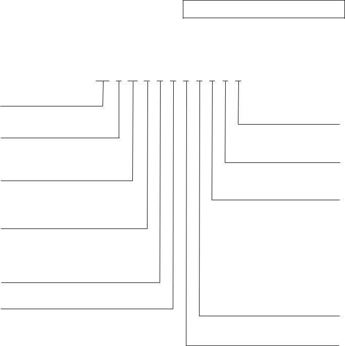
Fig. 2 — Corner Weights
7

a38-7115 |
SIZES 025 TO 060
a38-7116 |
SIZES 070 TO 100
Fig. 3 — Rigging Labels
a38-7130
LEGEND
ASTM — American Society for Testing and Materials
4 x 24 in. ASTM “C” CHANNEL
Fig. 4 — Perimeter Support Channel
8
9
|
|
STANDARD |
CENTER OF GRAVITY, |
HEIGHT, |
POWER ENTRY, |
SERVICE VALVE |
|||
UNIT |
in. (mm) |
in. (mm) |
in. (mm) |
CONNECTIONS, in. (mm) |
|||||
|
|
WEIGHT, lb (kg) |
X |
Y |
H |
P |
Suction |
Liquid |
|
|
|
|
|||||||
|
38APS025 |
1077 (489) |
17.8 (452) |
36.9 (937) |
61.0 (1549) |
24.9 (632) |
15/8 (41) |
5/8 (16) |
|
|
38APD025 |
1095 (497) |
17.8 (452) |
37.0 (940) |
13/8 (35) |
5/8 (16) |
|||
|
|
|
|||||||
Standard |
38APS027 |
1240 (563) |
18.2 (462) |
37.6 (955) |
|
|
15/8 (41) |
5/8 (16) |
|
38APD027 |
1258 (571) |
18.2 (462) |
37.6 (955) |
73.1 (1857) |
36.9 (937) |
13/8 (35) |
5/8 (16) |
||
|
|||||||||
|
38APS030 |
1246 (565) |
18.2 (462) |
37.5 (953) |
15/8 (41) |
7/8 (22) |
|||
|
|
|
|||||||
|
38APD030 |
1264 (573) |
18.2 (462) |
37.6 (955) |
|
|
13/8 (35) |
5/8 (16) |
|
|
38APS025 |
1113 (505) |
17.8 (452) |
36.9 (937) |
66.5 (1689) |
24.9 (632) |
15/8 (41) |
5/8 (16) |
|
|
38APD025 |
1131 (513) |
17.8 (452) |
37.0 (940) |
13/8 (35) |
5/8 (16) |
|||
|
|
|
|||||||
Low Sound |
38APS027 |
1276 (579) |
18.2 (462) |
37.6 (955) |
|
|
15/8 (41) |
5/8 (16) |
|
38APD027 |
1294 (587) |
18.2 (462) |
37.6 (955) |
78.6 (1996) |
36.9 (937) |
13/8 (35) |
5/8 (16) |
||
|
|||||||||
|
38APS030 |
1282 (582) |
18.2 (462) |
37.5 (953) |
15/8 (41) |
7/8 (22) |
|||
|
|
|
|||||||
|
38APD030 |
1300 (590) |
18.2 (462) |
37.6 (955) |
|
|
13/8 (35) |
5/8 (16) |
|
NOTES:
1.Be sure to use a wet rag to remove all valve cores before brazing field piping.
2.Do not cap or otherwise obstruct the liquid line temperature relief.
3.A 7/8 in. (22.4 mm) diameter hole is provided for locating field power wiring. Actual hole size required depends on field wire sizing.
4.A 0.437 in. (11.1 mm) diameter hole is used for mounting unit.
5.Unit must have clearances as follows: Top - Do not restrict.
Coil End - 72 in. (1829) from solid surface.
Panel Side - 48 in. (1219) per NEC (National Electrical Code, U.S.A. Standard).
6.Unit height dimension for standard and low sound unit with stack fan option.
7.Installation in a pit is not recommended.
8.Unit can be handled using the fork truck lift pockets.
9.Dimensions shown in inches (mm).
7101-a38
Fig. 5 — 38AP Unit Dimensions, Sizes 025-030
|
|
|
STANDARD |
CENTER OF GRAVITY, |
|
|
HEIGHT, |
|
|
SERVICE VALVE |
||||||||||||||||||||
UNIT |
|
in. (mm) |
|
|
|
in. (mm) |
|
|
CONNECTIONS, in. (mm) |
|||||||||||||||||||||
|
|
|
WEIGHT, lb (kg) |
X |
|
Y |
|
|
|
|
|
|
H |
|
|
Suction |
Liquid |
|||||||||||||
|
|
|
|
|
|
|
|
|
|
|
|
|
|
|||||||||||||||||
|
|
38APS040 |
1968 |
(893) |
35.0 (869) |
44.0 |
(1118) |
|
|
|
|
|
|
|
|
|
|
|
|
|
|
|
21/8 (54) |
7/8 (22) |
|
|||||
|
|
38APD040 |
2094 |
(950) |
33.7 (856) |
44.1 |
(1120) |
|
|
|
|
|
|
|
|
|
|
|
|
|
|
|
15/8 (41) |
5/8 (16) |
|
|||||
Standard |
|
38APS050 |
1977 |
(897) |
34.9 (886) |
44.0 |
(1118) |
73.0 (1854) |
|
21/8 (54) |
7/8 (22) |
|
||||||||||||||||||
|
|
38APD050 |
2120 |
(961) |
33.4 (848) |
44.1 |
(1120) |
|
|
|
|
|
|
|
|
|
|
|
|
|
|
|
15/8 (41) |
5/8 (16) |
|
|||||
|
|
38APD060 |
2227 (1010) |
34.4 (874) |
44.1 |
(1120) |
|
|
|
|
|
|
|
|
|
|
|
|
|
|
|
15/8 (41) |
5/8 (16) |
|
||||||
|
|
38APS040 |
2022 |
(917) |
35.0 (869) |
44.0 |
(1118) |
|
|
|
|
|
|
|
|
|
|
|
|
|
|
|
21/8 (54) |
7/8 (22) |
|
|||||
|
|
38APD040 |
2148 |
(974) |
33.7 (856) |
44.1 |
(1120) |
|
|
|
|
|
|
|
|
|
|
|
|
|
|
|
15/8 (41) |
5/8 (16) |
|
|||||
Low Sound |
|
38APS050 |
2031 |
(921) |
34.9 (886) |
44.0 |
(1118) |
78.5 (1994) |
|
21/8 (54) |
7/8 (22) |
|
||||||||||||||||||
|
|
38APD050 |
2174 |
(986) |
33.4 (848) |
44.1 |
(1120) |
|
|
|
|
|
|
|
|
|
|
|
|
|
|
|
15/8 (41) |
5/8 (16) |
|
|||||
|
|
38APD060 |
2299 (1043) |
34.4 (874) |
44.1 |
(1120) |
|
|
|
|
|
|
|
|
|
|
|
|
|
|
|
15/8 (41) |
5/8 (16) |
|
||||||
|
|
|
|
|
|
|
|
|
|
|
|
|
|
|
|
|
|
|
|
|
|
|
|
|
|
|
|
|
|
|
|
|
|
|
|
|
|
|
|
|
|
|
|
|
|
|
|
|
|
|
|
|
|
|
|
|
|
|
|
|
|
|
|
|
|
|
|
|
|
|
|
|
|
|
|
|
|
|
|
|
|
|
|
|
|
|
|
|
|
|
|
|
|
|
|
|
|
|
|
|
|
|
|
|
|
|
|
|
|
|
|
|
|
|
|
|
|
|
|
|
|
|
|
|
|
|
|
|
|
|
|
|
|
|
|
|
|
|
|
|
|
|
|
|
|
|
|
|
|
|
|
|
|
|
NOTES:
1.Be sure to use a wet rag to remove all valve cores before brazing field piping.
2.Do not cap or otherwise obstruct the liquid line temperature relief.
3.A 7/8 in. (22.4 mm) diameter hole is provided for locating field power wiring. Actual hole size required depends on field wire sizing.
4.A 0.437 in. (11.1 mm) diameter hole is used for mounting unit.
5.Unit must have clearances as follows: Top - Do not restrict.
Coil End - 72 in. (1829) from solid surface.
Panel Side - 48 in. (1219) per NEC (National Electrical Code, U.S.A. Standard).
6.Unit height dimension for standard and low sound unit with stack fan option.
7.Installation in a pit is not recommended.
8.Unit can be handled using the fork truck lift pockets.
9.Dimensions shown in inches (mm).
10.Sizes 040 and 050 units have 3 condenser fans. Size 060 units have 4 condenser fans.
7102-a38
10
Fig. 6 — 38AP Unit Dimensions, Sizes 040-060
|
|
|
|
CENTER OF GRAVITY, |
HEIGHT, |
SERVICE VALVE CONNECTIONS, |
|||||
|
|
STANDARD |
|
in. (mm) |
|
||||||
UNIT |
|
in. (mm) |
|
in. (mm) |
|
|
|||||
|
|
WEIGHT, lb (kg) |
|
|
|
|
|
Suction |
Liquid |
||
|
|
|
|
|
X |
|
Y |
H |
Circuit A |
Circuit B |
|
|
|
|
|
|
|
|
|||||
Standard |
38APD070 |
2450 |
(1111) |
50.9 |
(1293) |
40.6 |
(1031) |
73.0 (1854) |
21/8 (54) |
15/8 (41) |
7/8 (22) |
Low Sound |
38APD070 |
2522 |
(1144) |
50.9 |
(1293) |
40.6 |
(1031) |
78.5 (1994) |
21/8 (54) |
15/8 (41) |
7/8 (22) |
NOTES:
1.Be sure to use a wet rag to remove all valve cores before brazing field piping.
2.Do not cap or otherwise obstruct the liquid line temperature relief.
3.A 7/8 in. (22.4 mm) diameter hole is provided for locating field power wiring. Actual hole size required depends on field wire sizing.
4.A 0.437 in. (11.1 mm) diameter hole is used for mounting unit.
5.Unit must have clearances as follows: Top - Do not restrict.
Coil, Panel and Rear Side - 72 in. (1829) from solid surface.
6.Unit height dimension for standard and low sound unit with stack fan option.
7.Installation in a pit is not recommended.
8.Unit can be handled using crane.
9.Dimensions shown in inches (mm).
11 |
7103-a38 |
Fig. 7 — 38AP Unit Dimensions, Size 070
 Loading...