


GEMINI™ SELECT 38APS025-050,38APD025-100 Commercial Air-Cooled Condensing Units with COMFORTLINK™ Controls 50/60 Hz
Controls, Start-Up, Operation,
Service, and Troubleshooting
CONTENTS
Page
SAFETY CONSIDERATIONS . . . . . . . . . . . . . . . . . . . . .1,2
GENERAL . . . . . . . . . . . . . . . . . . . . . . . . . . . . . . . . . . . . . . . . 2
CONTROLS . . . . . . . . . . . . . . . . . . . . . . . . . . . . . . . . . . . 2-20
General . . . . . . . . . . . . . . . . . . . . . . . . . . . . . . . . . . . . . . . . . . 2
Conventions Used in This Manual. . . . . . . . . . . . . . . . 2
Display Module Usage . . . . . . . . . . . . . . . . . . . . . . . . . . 17
•SCROLLING MARQUEE DISPLAY
•ACCESSORY NAVIGATOR™ DISPLAY MODULE
Main Base Board (MBB) . . . . . . . . . . . . . . . . . . . . . . . . . 18
Current Sensor Board (CSB) . . . . . . . . . . . . . . . . . . . . 18
Energy Management Module (EMM) . . . . . . . . . . . . . 18
Compressor Expansion Module (CXB) . . . . . . . . . . 19
AUX Board (AUX). . . . . . . . . . . . . . . . . . . . . . . . . . . . . . . . 19
Enable/Off/Remote Contact Switch. . . . . . . . . . . . . . 19
Emergency On/Off Switch . . . . . . . . . . . . . . . . . . . . . . . 19
Board Addresses. . . . . . . . . . . . . . . . . . . . . . . . . . . . . . . . 19
Control Module Communication. . . . . . . . . . . . . . . . . 19
Carrier Comfort Network® (CCN) Interface. . . . . . . 20
OPERATING DATA. . . . . . . . . . . . . . . . . . . . . . . . . . . . 20-33
Sensors . . . . . . . . . . . . . . . . . . . . . . . . . . . . . . . . . . . . . . . . . 20
•RETURN AIR TEMPERATURE (RAT) ACCESSORY
•SUPPLY AIR TEMPERATURE (SAT) ACCESSORY
•COMPRESSOR RETURN GAS TEMPERATURE SENSOR (RGT)
•OUTDOOR-AIR TEMPERATURE SENSOR (OAT)
•DISCHARGE TEMPERATURE THERMISTOR (DTT)
•SPACE TEMPERATURE SENSOR (SPT)
Fan Status Input. . . . . . . . . . . . . . . . . . . . . . . . . . . . . . . . . 23 Thermostat Input. . . . . . . . . . . . . . . . . . . . . . . . . . . . . . . . 23
Pressure Transducer Inputs. . . . . . . . . . . . . . . . . . . . . 23 Energy Management Module . . . . . . . . . . . . . . . . . . . . 23
Control. . . . . . . . . . . . . . . . . . . . . . . . . . . . . . . . . . . . . . . . . . 23 Head Pressure Control . . . . . . . . . . . . . . . . . . . . . . . . . . 26 Service Test. . . . . . . . . . . . . . . . . . . . . . . . . . . . . . . . . . . . . 28 Operating Modes. . . . . . . . . . . . . . . . . . . . . . . . . . . . . . . . 28
Operation of Machine Based on Control
Method . . . . . . . . . . . . . . . . . . . . . . . . . . . . . . . . . . . . . . . 28 Set Point Adjustment. . . . . . . . . . . . . . . . . . . . . . . . . . . . 29 Demand Limit . . . . . . . . . . . . . . . . . . . . . . . . . . . . . . . . . . . 31
•DEMAND LIMIT (2-Stage Switch Controlled)
•EXTERNALLY POWERED DEMAND LIMIT (4 to 20 mA Controlled)
•DEMAND LIMIT (CCN Loadshed Controlled)
Cooling Set Point (4 to 20 mA) . . . . . . . . . . . . . . . . . . 32
Digital Scroll Option. . . . . . . . . . . . . . . . . . . . . . . . . . . . . 32
PRE-START-UP . . . . . . . . . . . . . . . . . . . . . . . . . . . . . . . . . . 33 System Check. . . . . . . . . . . . . . . . . . . . . . . . . . . . . . . . . . . 33
START-UP . . . . . . . . . . . . . . . . . . . . . . . . . . . . . . . . . . . . 33-49 Preliminary Charge. . . . . . . . . . . . . . . . . . . . . . . . . . . . . . 33 Adjust Refrigerant Charge . . . . . . . . . . . . . . . . . . . . . . 34
Check Compressor Oil Level . . . . . . . . . . . . . . . . . . . . 47
Final Checks . . . . . . . . . . . . . . . . . . . . . . . . . . . . . . . . . . . . 47
Page
Oil Charge . . . . . . . . . . . . . . . . . . . . . . . . . . . . . . . . . . . . . . 47
Actual Start-Up. . . . . . . . . . . . . . . . . . . . . . . . . . . . . . . . . . 47
OPERATION. . . . . . . . . . . . . . . . . . . . . . . . . . . . . . . . . . . . . 48
Operating Limitations . . . . . . . . . . . . . . . . . . . . . . . . . . . 48
•AMBIENT LIMITATIONS
•VOLTAGE (ALL UNITS)
Operation Sequence . . . . . . . . . . . . . . . . . . . . . . . . . . . . 48
SERVICE . . . . . . . . . . . . . . . . . . . . . . . . . . . . . . . . . . . . . 49-59
Electronic Components . . . . . . . . . . . . . . . . . . . . . . . . . 49
• CONTROL COMPONENTS
Thermistors . . . . . . . . . . . . . . . . . . . . . . . . . . . . . . . . . . . . . 49
Pressure Transducers. . . . . . . . . . . . . . . . . . . . . . . . . . . 54
Condenser Fans . . . . . . . . . . . . . . . . . . . . . . . . . . . . . . . . 54
Motormaster® V Controller . . . . . . . . . . . . . . . . . . . . . . 54
•GENERAL OPERATION
•CONFIGURATION
•DRIVE PROGRAMMING
•EPM CHIP
•LOSS OF CCN COMMUNICATIONS
•TROUBLESHOOTING
•REPLACING DEFECTIVE MODULES
Compressors . . . . . . . . . . . . . . . . . . . . . . . . . . . . . . . . . . . 59
MAINTENANCE . . . . . . . . . . . . . . . . . . . . . . . . . . . . . . .59,60
Recommended Maintenance Schedule . . . . . . . . . . 59
Microchannel Heat Exchanger (MCHX) Condenser
Coil Maintenance and Cleaning
Recommendations . . . . . . . . . . . . . . . . . . . . . . . . . . . 60
TROUBLESHOOTING . . . . . . . . . . . . . . . . . . . . . . . . 60-66
Complete Unit Stoppage and Restart. . . . . . . . . . . . 60
•GENERAL POWER FAILURE
•UNIT ENABLE-OFF-REMOTE CONTACT SWITCH IS OFF
•FAN STATUS INPUT OPEN
•OPEN 24-V CONTROL CIRCUIT BREAKER(S)
•COOLING LOAD SATISFIED
•THERMISTOR FAILURE
•COMPRESSOR SAFETIES
Alarms and Alerts . . . . . . . . . . . . . . . . . . . . . . . . . . . . . . . 61
APPENDIX A — DISPLAY TABLES . . . . . . . . . . . 67-78
APPENDIX B — CCN TABLES . . . . . . . . . . . . . . . . 79-84
START-UP CHECKLIST FOR 38AP SPLIT SYSTEM CONDENSING UNIT . . . . . . . . . . . . . . . . . . . .CL-1-CL-5
SAFETY CONSIDERATIONS
Installing, starting up, and servicing this equipment can be hazardous due to system pressures, electrical components, and equipment location (roof, elevated structures, mechanical rooms, etc.). Only trained, qualified installers and service mechanics should install, start up, and service this equipment.
Manufacturer reserves the right to discontinue, or change at any time, specifications or designs without notice and without incurring obligations.
Catalog No. 04-53380003-01 |
Printed in U.S.A. |
Form 38AP-1T |
Pg 1 |
210 11-09 |
Replaces: New |
When working on this equipment, observe precautions in the literature, and on tags, stickers, and labels attached to the equipment, and any other safety precautions that apply. Follow all safety codes. Wear safety glasses and work gloves. Use care in handling, rigging, and setting this equipment, and in handling all electrical components.
 WARNING
Electrical shock can cause personal injury and death. Shut off all power to this equipment during installation and service. There may be more than one disconnect switch. Tag all disconnect locations to alert others not to restore power until work is completed.
 WARNING
DO NOT VENT refrigerant relief valves within a building. Outlet from relief valves must be vented outdoors in accordance with the latest edition of ANSI/ASHRAE (American National Standards Institute/American Society of Heating, Refrigeration and Air Conditioning Engineers) 15 (Safety Code for Mechanical Refrigeration). The accumulation of refrigerant in an enclosed space can displace oxygen and cause asphyxiation. Provide adequate ventilation in enclosed or low overhead areas. Inhalation of high concentrations of vapor is harmful and may cause heart irregularities, unconsciousness or death. Misuse can be fatal. Vapor is heavier than air and reduces the amount of oxygen available for breathing. Product causes eye and skin irritation. Decomposition products are hazardous.
 WARNING
DO NOT attempt to unbraze factory joints when servicing this equipment. Compressor oil is flammable and there is no way to detect how much oil may be in any of the refrigerant lines. Cut lines with a tubing cutter as required when performing service. Use a pan to catch any oil that may come out of the lines and as a gage for how much oil to add to system. DO NOT re-use compressor oil.
 CAUTION
This unit uses a microprocessor-based electronic control system. Do not use jumpers or other tools to short out components, or to bypass or otherwise depart from recommended procedures. Any short-to-ground of the control board or accompanying wiring may destroy the electronic modules or electrical components.
 CAUTION
Puron® refrigerant (R-410A) systems operate at higher pressures than standard R-22 systems. Do not use R-22 service equipment or components on Puron refrigerant equipment. If service equipment is not rated for Puron refrigerant, equipment damage or personal injury may result.
 CAUTION
Refrigerant charge must be removed slowly to prevent loss of compressor oil that could result in compressor failure.
GENERAL
This publication contains Controls Start-Up, Service, Operation, and Troubleshooting information for the Gemini™ Select 38AP condensing units with ComfortLink controls. See Table 1 for unit size information.
|
Table 1 — Unit Sizes |
||
|
|
|
|
38AP UNIT SIZE |
NOMINAL CAPACITY, |
||
TONS, 60 Hz |
|||
|
|
||
025 |
|
25 |
|
027 |
|
27 |
|
030 |
|
30 |
|
040 |
|
40 |
|
050 |
|
50 |
|
060 |
|
60 |
|
070 |
|
70 |
|
080 |
|
80 |
|
090 |
|
90 |
|
100 |
|
100 |
|
CONTROLS
General — The 38AP air-cooled condensing unit contains the ComfortLink™ electronic control system that controls and monitors all operations of the unit.
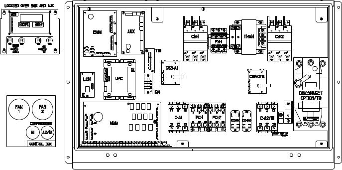
The control system is composed of several components as listed in the sections below. See Fig. 1-3 for typical control box drawing. See Fig. 4-17 for power and control wiring.
Conventions Used in This Manual — The following conventions for discussing configuration points for the local display (scrolling marquee or Navigator™ accessory) will be used in this manual.
Point names will be written with the mode name first, then any sub-modes, then the point name, each separated by an arrow symbol ( . Names will also be shown in bold and italics. As an example, the Lead/Lag Circuit Select Point, which is located in the Configuration mode, Option sub-mode, would be written as Configuration OPT2 LLCS.
This path name will show the user how to navigate through the local display to reach the desired configuration. The user would scroll through the modes and sub-modes using the  and
and  keys. The arrow symbol in the path name represents pressing ENTER to move into the next level of the menu structure.
When a value is included as part of the path name, it will be shown at the end of the path name after an equals sign. If the value represents a configuration setting, an explanation will be shown in parenthesis after the value. As an example,
Configuration OPT2 LLCS = 2 (Circuit A leads).
Pressing the ESCAPE and ENTER keys simultaneously will scroll an expanded text description of the point name or
value across the display. The expanded description is shown in the local display tables but will not be shown with the path names in text.
The CCN (Carrier Comfort Network®) point names are also referenced in the local display tables for users configuring the unit with CCN software instead of the local display. The CCN tables are located in Appendix B of the manual.
2
|
LEGEND |
AUX |
— Auxiliary |
C |
— Contactor |
CB |
— Circuit Breaker |
CCHR |
— Crankcase Heater Relay |
CSB |
— Current Sensor Board |
EMM |
— Energy Management Module |
EQUIP GND — Equipment Ground |
|
FB |
— Fuse Block |
FC |
— Fan Contactor |
LON |
— Local Operating Network |
MBB |
— Main Base Board |
SW |
— Switch |
TB |
— Terminal Block |
TRAN |
— Transformer |
UPC |
— Unitary Protocol Converter |
Fig. 1 — Component Arrangement — Unit Sizes 025-030
3
|
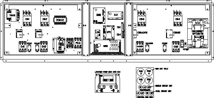
LEGEND |
AUX |
— Auxiliary |
C |
— Contactor |
CB |
— Circuit Breaker |
CCH |
— Crankcase Heater Relay |
CSB |
— Current Sensor Board |
EMM |
— Energy Management Module |
EQUIP GND — Equipment Ground |
|
FC |
— Fan Contactor |
FCB |
— Fan Circuit Breaker |
LON |
— Local Operating Network |
MBB |
— Main Base Board |
MM |
— Motormaster® |
SW |
— Switch |
TB |
— Terminal Block |
TRAN |
— Transformer |
UPC |
— Unitary Protocol Converter |
Fig. 2 — Component Arrangement — Unit Sizes 040-060
4
|
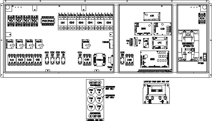
LEGEND |
AUX |
— Auxiliary |
C |
— Contactor |
CB |
— Circuit Breaker |
CCH |
— Crankcase Heater Relay |
CSB |
— Current Sensor Board |
CXB |
— Compressor Expansion Board |
EMM |
— Energy Management Module |
EQUIP GND — Equipment Ground |
|
FC |
— Fan Contactor |
FCB |
— Fan Circuit Breaker |
LON |
— Local Operating Network |
MBB |
— Main Base Board |
SW |
— Switch |
TB |
— Terminal Block |
TRAN |
— Transformer |
UPC |
— Unitary Protocol Converter |
Fig. 3 — Component Arrangement — Unit Sizes 070-100
5
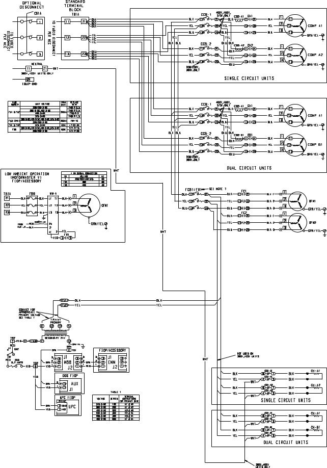
Fig. 4 — Power Wiring Schematic — 38APS,APD025-030
6
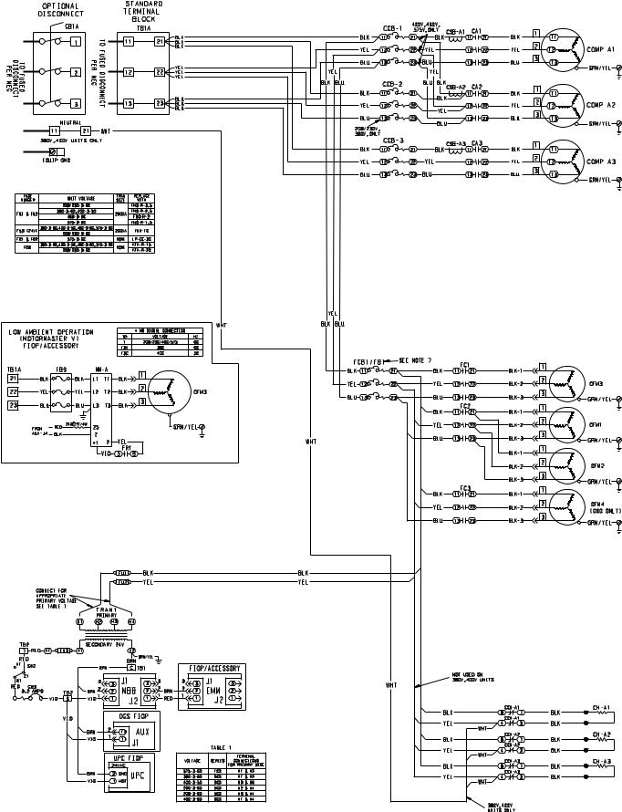
Fig. 5 — Power Wiring Schematic — 38APS040,050
7
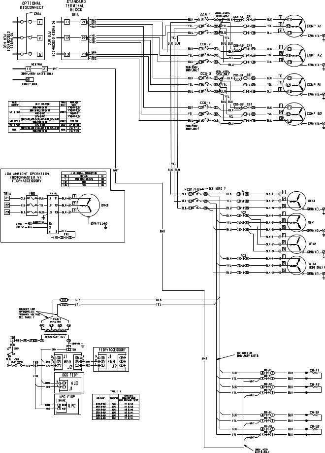
Fig. 6 — Power Wiring Schematic — 38APD040-060
8

Fig. 7 — Power Wiring Schematic — 38APD070-100 |
9
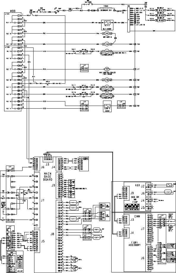
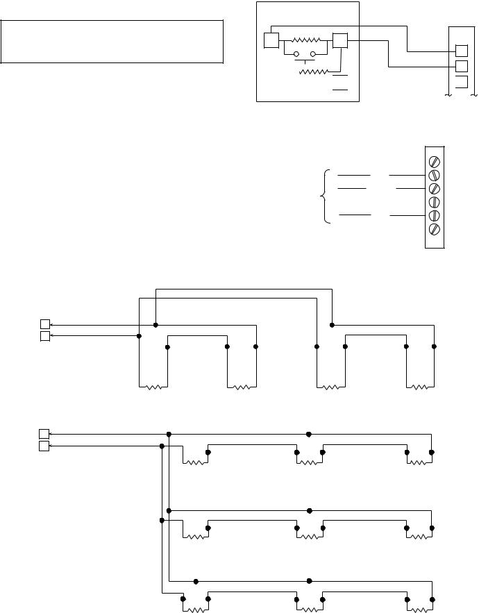
Fig. 8 — Control Wiring Schematic — 38APS025-050
10
Fig. 9 — Control Wiring Schematic — 38APD025-060
11
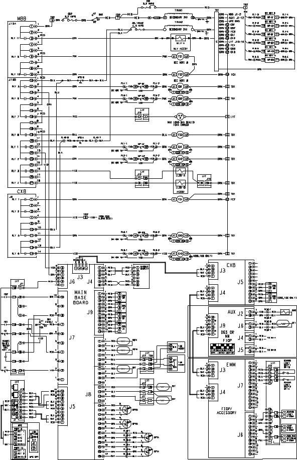
Fig. 10 — Control Wiring Schematic — 38APD070-100
12
Legend and Notes for Fig. 4-10
|
LEGEND |
ACCSY |
— Accessory |
ALM |
— Alarm |
AMPS |
— Amperes |
AUX |
— Auxiliary |
C |
— Contactor |
CB |
— Circuit Breaker |
CCB |
— Compressor Circuit Breaker |
CCH |
— Crankcase Heater Relay |
CH |
— Crankcase Heater |
COMP |
— Compressor |
CSB |
— Current Sensor Board |
CXB |
— Compressor Expansion Module |
DGS |
— Digital Scroll |
DPT |
— Discharge Pressure Transducer |
DTT |
— Discharge Temperature Thermistor |
DUS |
— Digital Unloaded Solenoid |
EMM |
— Energy Management Module |
EQUIP GND |
— Equipment Ground |
FB |
— Fuse Block |
FC |
— Fan Contactor |
FCB |
— Fan Circuit Breaker |
FIOP |
— Factory-Installed Option |
FR |
— Fan Relay |
FS |
— Fan Status |
FU |
— Fuse |
GND |
— Ground |
HPS |
— High Pressure Switch |
LLSV |
— Liquid Line Solenoid Valve |
LVT |
— Low Voltage Terminal |
MBB |
— Main Base Board |
MLV |
— Minimum Load Valve |
MM |
— Motormaster |
MP |
— Modular Motor Protector |
NEC |
— National Electrical Code |
OAT |
— Outdoor Air Thermistor |
OFM |
— Outdoor Fan Motor |
OPT |
— Option |
PL |
— Plug |
RAT |
— Return Air Temperature |
RGT |
— Return Gas Temperature |
RLY |
— Relay |
SAT |
— Supply Air Temperature |
SEN |
— Sensor Terminal Block |
SET |
— Set Point Terminal Block |
SPT |
— Suction Pressure Transducer |
SW |
— Switch |
TB |
— Terminal Block |
TEMP |
— Temperature |
TRAN |
— Transformer |
UPC |
— Unitary Protocol Converter |
Y |
— Cool Stage |
NOTES:
1.Factory wiring is in accordance with UL (Underwriters Laboratories) 1995 standards. Any field modifications or additions must be in compliance with all applicable codes.
2.Use 75 C minimum wire for field power supply.
3. All field interlock contacts must have a minimum rating of 2 amps at 24-vac sealed. See field interlock wiring.
4.Compressor and fan motors are thermally protected. Threephase motors protected against single-phase conditions.
5.Terminals 13 and 14 of LVT are for field connection of remote on-off. The contact must be rated for dry circuit application capable of handling a 5-vdc, 1 mA to 20 mA load.
6.For 500 series unit operation at 208-3-60 line voltage, TRAN1 primary connections must be moved to terminals H3 and H4.
7.For 575-3-60 units, fan circuit breakers FCB1 and FCB2 are replaced with fuse blocks FB1 and FB2.
8.For units with low ambient Motormaster® V factory-installed option or field-installed acessory, fan contactors FC1 and FC2 are replaced with fan relays FR1 and FR2.
9.MP-A1 not used in the following units: 070-100: 400-v, 460-v units without digital scroll
10.MP-A2 not used in the following units: 070-100: 400-v, 460-v
11.MP-B1 not used in the following units:
070: all units 080-100: 400-v, 460-v
12.MP-B2 not used in the following units:
070:all units
080-100: 400-v, 460-v
13.MP-A3 not used in the following units: 090,100: 400-v, 460-v
14.MP-B3 not used in the following units:
070: all units 080-100: 400-v, 460-v
15.Jumper plug required when modular motor protector is not used.
13
a38-7122
|
|
|
|
|
|
|
|
|
|
|
|
|
LEGEND |
|
|
|
|
EQUIP GND |
— |
Equipment Ground |
|
|
|
NEC |
— |
National Electrical Code |
|
|
|
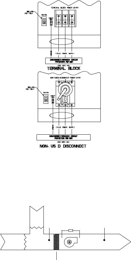
NOTES:
1.Factory wiring is in accordance with UL 1995 standards. Field modifications or additions must be in compliance with all applicable codes.
2.All units or modules have single point primary power connection. Main power must be supplied from a field or factory-supplied disconnect.
3.Wiring for main field supply must be rated 75 C. Use copper conductors only.
a.Incoming wire size range for terminal block with MCA (minimum circuit amps) up to 175 amps is 14 AWG (American Wire Gage) to 2/0.
b.Incoming wire size range for terminal block with MCA from 175.1 amps to 420 amps is 2 AWG to 600 kcmil.
c.Incoming wire size range for non-fused disconnect with MCA up to 100 amps is 14 AWG to 1/0.
d.Incoming wire size range for non-fused disconnect with MCA from
100.1amp to 200 amps is 6 AWG to 350 kcmil.
e.Incoming wire size range for non-fused disconnect with MCA from
200.1amp to 450 amps is 3/0 to 500 kcmil.
4.Refer to certified dimensional drawings for exact locations of the main power and control power entrance locations.
Fig. 11 — Field Power Wiring
a38-7133 |
RETURN |
AIR |
|
|
MAT/RAT |
FS1* |
SAT |
|
OUTSIDE |
|
|
DUCT |
|
AIR |
|
|
SUPPLY |
|
|
|
FAN |
|
|
LEGEND |
|
|
|
FS1 |
— Fan Status Switch (24-v) |
EVAPORATOR |
|
|
MAT |
— Mixed Air Temperature Sensor |
COIL |
|
|
RAT |
— Return Air Temperature Sensor |
|
|
|
SAT |
— Supply Air Temperature Sensor |
|
|
|
*FS1 can be pressure differential switch (shown), motor current detection, or sail switch.
Fig. 12 — MAT/RAT and SAT Sensor Layout
14
LVT
1 2 3 4 5 6 7 8 9 10 11 12 13 14 15 16 17 18 19 20 21 22 23 24 25 TERMINAL STRIP
FS 1
|
REMOTE |
ALM |
ON/OFF |
|
|
R |
|
|
COOL 2 |
a38-7125 |
COOL 1 |
|
|
|
|
V-A |
|
|
|
LLS |
LLSV-B* |
|
|
EE NOTE 6 |
|
|
||
|
|
||
|
|
|
S |
*Not required for single circuit units.
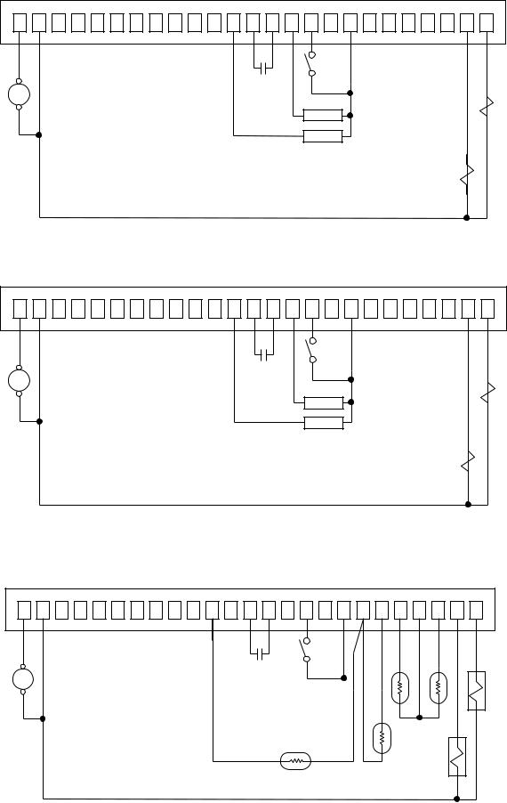
Fig. 13 — Constant Volume Application Wiring Diagram 2-Stage Thermostat Control, Sizes 025-030 — without Digital Scroll Option
LVT
1 2 3 4 5 6 7 8 9 10 11 12 13 14 15 16 17 18 19 20 21 22 23 24 25 TERMINAL STRIP
FS 1
REMOTE
ALM ON/OFF R
COOL2
COOL 1
|
|
|
V-A |
|
|
|
LLS |
|
|
|
|
SLLV-B |
|
6 |
|
|
|
NOTEEE |
|
* |
|
|
|
|
|
|
S |
|
|
|
|
*See Fig. 12 for MAT/RAT and SAT location. |
a38-7126 |
†Not required for single circuit units. |
|
Fig. 14 — Constant Volume Application Wiring Diagram 2-Stage Thermostat Control — with Digital Scroll Option, Sizes 025-030 or All Sizes 040-100
LVT
1 2 3 4 5 6 7 8 9 10 11 12 13 14 15 16 17 18 19 20 21 22 23 24 25 TERMINAL STRIP
FS 1
REMOTE
ALM ON/OFF R
SAT *
a38-7127
SPT |
SA |
|
MAT/RAT * |
|
LLSV-A |
|
† |
6 |
|
NOTE |
|
|
SV-B |
|
|
LL |
EE |
|
|
S |
*See Fig. 12 for MAT/RAT and SAT location. †Not required for single circuit units.
Fig. 15 — Constant Volume Application Wiring Diagram Space Temperature Sensor Control, Sizes 025-100
15
LVT
1 2 3 4 5 6 7 8 9 10 11 12 13 14 15 16 17 18 19 20 21 22 23 24 25 TERMINAL STRIP
|
|
FS 1 |
|
|
REMOTE |
|
|
ALM |
ON/OFF |
|
|
|
|
LLSV-A |
|
R |
|
MAT/RAT * |
|
|
|
||
|
|
† |
6 |
|
SAT * |
NOTE |
|
|
B-VS |
||
|
|
|
|
|
|
LL |
EE |
|
|
|
S |
a38-7128
*See Fig. 12 for MAT/RAT and SAT location. †Not required for single circuit units.
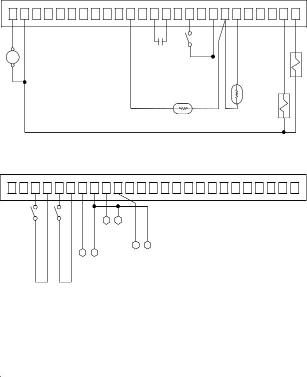
Fig. 16 — Variable Air Volume Application Wiring Diagram, Sizes 025-100
LVT
1 2 3 4 5 6 7 8 9 10 11 12 13 14 15 16 17 18 19 20 21 22 23 24 25 TERMINAL STRIP
LIMIT STEP 1 |
LIMIT STEP 2 |
|
|
+ |
– |
|
|
|
|
|
||
|
|
|
TEMP |
RESET 4-20 mA |
|
|
|
|
|
|
||
|
|
+ |
|
– |
|
|||||||
+ |
– |
|
|
|
|
|
|
|
REQUESTED |
|
||
DEMAND |
DEMAND |
|
|
|
|
|
|
|
|
|||
DEMAND |
LIMIT 4-20 mA |
|
|
|
|
COOLING |
SETPOINT/ |
CAPACITY |
4-20 mA |
|||
|
|
|
|
|
|
|
|
|
|
|
|
|
a38-7129
Fig. 17 — Optional Energy Management Module Wiring
Legend and Notes for Fig. 13-17
|
|
|
|
|
|
|
LEGEND |
ALM R |
|
— Alarm Relay (24-v), 5-va Maximum |
|||||
COOL1 |
|
— Thermostat Stage 1 (24-v) |
|||||
COOL2 |
|
— Thermostat Stage 2 (24-v) |
|||||
FS1 |
|
— Fan Status Switch (24-v) |
|||||
LLSV |
|
— Liquid Line Solenoid Valve |
|||||
LVT |
|
— Low Voltage Terminal |
|||||
MAT |
|
— Mixed Air Temperature Sensor |
|||||
RAT |
|
— Return Air Temperature Sensor |
|||||
SA |
|
— Set Point Adjustment (T-56, T-59) |
|||||
SAT |
|
— Supply Air Temperature Sensor |
|||||
SPT |
|
— Space Temperature Sensor (T-55, T-56, T-59) |
|||||
|
|
|
|
|
|
|
Field Control Wiring |
|
|
|
|
|
|
|
|
NOTES:
1.Factory wiring is in accordance with UL 1995 standards. Field modifications or additions must be in compliance with all applicable codes.
2.All units or modules have single point primary power connection. Main power must be supplied from a field or factorysupplied disconnect.
3.Wiring for main field supply must be rated 75 C. Use copper conductors only.
a.Incoming wire size range for terminal block with MCA (minimum circuit amps) up to 175 amps is 14 AWG (American Wire Gage) to 2/0.
b.Incoming wire size range for terminal block with MCA from 175.1 amps to 420 amps is 2 AWG to 600 kcmil.
c.Incoming wire size range for non-fused disconnect with MCA up to 100 amps is 14 AWG to 1/0.
d.Incoming wire size range for non-fused disconnect with MCA from 100.1 amp to 200 amps is 6 AWG to 350 kcmil.
e.Incoming wire size range for non-fused disconnect with MCA from 200.1 amp to 450 amps is 3/0 to 500 kcmil.
4.Terminals 1 and 2 of the LVT are for the alarm relay. The maximum load allowed for the alarm relay is 5-va sealed and 10-va inrush at 24-v. Field power supply is not required.
5.Refer to certified dimensional drawings for exact locations of the main power and control power entrance locations.
6.Terminals 24, 25, and 2 of the LVT are for the control of the field-supplied LLSV. The maximum load allowed for the LLSV is 15-va sealed and 30-va inrush at 24-v. Field power supply is not required.
7.LLSV (24-v) should be 15-va maximum per valve as required.
8.Installation of fan status switch (FS1) is recommended.
9.The contacts for remote ON/OFF, fan status, and demand limit options must be rated for dry circuit application capable of handling a 24-vac load up to 50 mA.
16
Display Module Usage
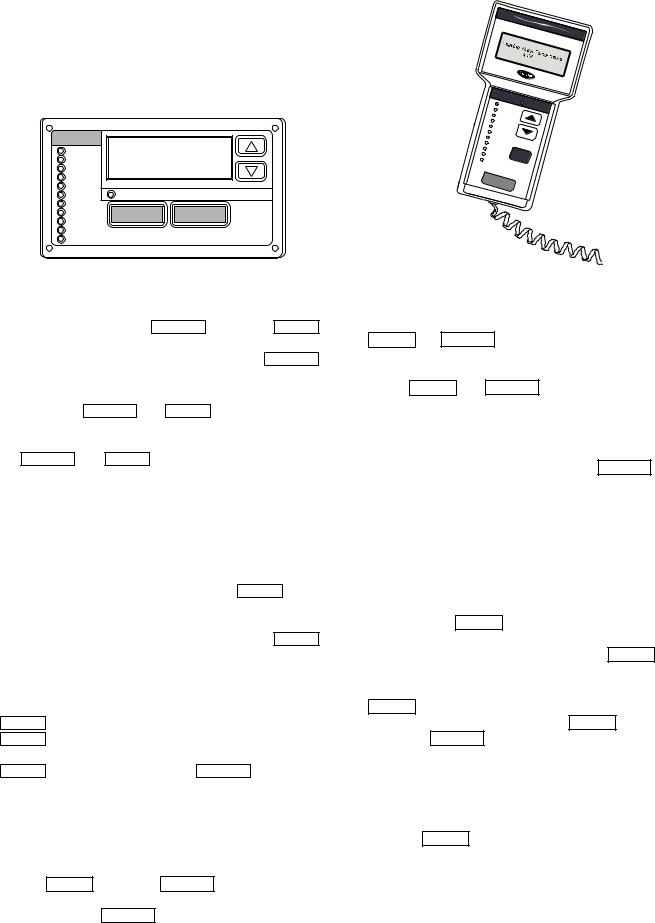
SCROLLING MARQUEE DISPLAY — This device is the keypad interface used for accessing unit information, reading sensor values, and testing the unit. See Fig. 18. The scrolling marquee display is a 4-key, 4-character, 16-segment LED (light-emitting diode) display. Eleven mode LEDs are located on the display as well as an Alarm Status LED. See Appendix A — Display Tables for further details.
MODE |
|
|
|
Run Status |
|
|
|
Service Test |
|
|
|
Temperature |
|
|
|
Pressures |
|
|
|
Setpoints |
|
|
|
Inputs |
Alarm Status |
|
|
Outputs |
ESCAPE |
ENTER |
|
Configuration |
|||
Time Clock |
|||
|
|
||
Operating Modes |
|
|
|
Alarms |
|
|
Fig. 18 — Scrolling Marquee Display
The scrolling marquee display module provides the user interface to the ComfortLink™ control system. The display has up and down arrow keys, an ESCAPE key, and an ENTER key. These keys are used to navigate through the different levels of the display structure. See Table 2. Press the ESCAPE key until the display is blank to move through the top 11 mode levels indicated by LEDs on the left side of the display.
Pressing the ESCAPE and ENTER keys simultaneously will scroll a clear language text description across the display indicating the full meaning of each display acronym. Pressing the ESCAPE and ENTER keys when the display is blank (Mode LED level) will return the scrolling marquee display to its default menu of rotating display items. In addition, the password will be disabled requiring that it be entered again before changes can be made to password protected items. Clear language descriptions will be displayed in English.
When a specific item is located, the display will flash showing the operator, the item, followed by the item value and then followed by the item units (if any). Press the ENTER key to stop the display at the item value. Items in the Configuration and Service Test modes are password protected. The display will flash PASS and WORD when required. Use the ENTER and arrow keys to enter the 4 digits of the password. The default password is 1111.
Changing item values or testing outputs is accomplished in the same manner. Locate and display the desired item. Press ENTER to stop the display at the item value. Press the ENTER key again so that the item value flashes. Use the arrow keys to change the value or state of an item and press the ENTER key to accept it. Press the ESCAPE key and the item, value, or units display will resume. Repeat the process as required for other items.
ACCESSORY NAVIGATOR™ DISPLAY MODULE — The Navigator module provides a mobile user interface to the
ComfortLink™ control system, which is only available as a field-installed accessory. The display has up and down arrow keys, an ENTER key, and an ESCAPE key. These keys are used to navigate through the different levels of the display structure. Press the ESCAPE key until ‘Select a Menu Item’ is displayed to move through the top 11 mode levels indicated by LEDs on the left side of the display. See Fig. 19.
ComfortLink
|
|
|
MO |
|
|
|
|
|
|
|
|
|
DE |
Alarm |
|
||
|
|
|
|
Run |
Status |
Status |
||
|
|
|
Ser |
|
||||
|
|
|
|
|
|
|
||
|
|
|
|
vice |
Test |
|
|
|
|
|
Tempe |
|
|
|
|||
|
|
ratures |
|
|
||||
|
|
P |
|
|
|
|
||
|
|
Se |
ressures |
|
|
|
||
|
|
tpoints |
|
|
|
|||
|
|
|
|
|
|
|||
|
|
Inputs |
|
|
|
|
||
|
Ou |
|
|
|
|
|
|
|
|
|
tputs |
|
|
|
|
||
|
Co |
|
|
|
|
|
|
|
|
|
nfigu |
|
|
|
|
||
|
Time |
|
ration |
|
|
|
||
Ope |
Clock |
|
|
ESC |
|
|||
rating |
Modes |
|
|
|||||
A |
larms |
|
|
|
|
|||
|
|
|
|
|
|
|
||
|
EN |
|
|
|
|
|
|
|
|
|
TER |
|
|
|
|
||
Fig. 19 — Accessory Navigator Display Module
Once within a Mode or sub-mode, a “>” indicates the currently selected item on the display screen. Pressing the ENTER and ESCAPE keys simultaneously will put the Navigator module into expanded text mode where the full meaning of all sub-modes, items and their values can be displayed. Pressing the ENTER and ESCAPE keys when the display says ‘Select Menu Item’ (Mode LED level) will return the Navigator module to its default menu of rotating display items (those items in Run Status VIEW). In addition, the password will be disabled, requiring that it be entered again before changes can be made to password protected items. Press the ESCAPE key to exit out of the expanded text mode.
NOTE: When the Language Selection (Configuration DISP LANG), variable is changed, all appropriate display expansions will immediately change to the new language. No power-off or control reset is required when reconfiguring languages.
When a specific item is located, the item name appears on the left of the display, the value will appear near the middle of the display and the units (if any) will appear on the far right of the display. Press the ENTER key at a changeable item and the value will begin to flash. Use the up and down arrow keys to change the value, and confirm the value by pressing the ENTER key.
Changing item values or testing outputs is accomplished in the same manner. Locate and display the desired item. Press ENTER so that the item value flashes. Use the arrow keys to change the value or state and press the ENTER key to accept it. Press the ESCAPE key to return to the next higher level of structure. Repeat the process as required for other items.
Items in the Configuration and Service Test modes are password protected. The words Enter Password will be displayed when required, with 1111 also being displayed. The default password is 0111. Use the arrow keys to change the number and press ENTER to enter the digit. Continue with the remaining digits of the password. The password can only be changed through CCN operator interface software such as ComfortWORKS®, ComfortVIEW™ and Service Tool.
17
Adjusting the Contrast — The contrast of the display can be adjusted to suit ambient conditions. To adjust the contrast of the Navigator module, press the ESCAPE key until the display reads, “Select a menu item.” Using the arrow keys move to the Configuration mode. Press ENTER to obtain access to this mode. The display will read:
> TEST OFF
METR OFF LANG ENGLISH
Pressing ENTER will cause the “OFF” to flash. Use the up or down arrow to change “OFF” to “ON”. Pressing ENTER will illuminate all LEDs and display all pixels in the view screen. Pressing ENTER and ESCAPE simultaneously allows the user to adjust the display contrast. Use the up or down arrows to adjust the contrast. The screen’s contrast will change with the adjustment. Press ENTER to accept the change. The Navigator module will keep this setting as long as it is plugged in to the LEN bus.
Adjusting the Backlight Brightness — The backlight of the display can be adjusted to suit ambient conditions. The factory default is set to the highest level. To adjust the backlight of the Navigator module, press the ESCAPE key until the display reads, “Select a menu item.” Using the arrow keys move to the Configuration mode. Press ENTER to obtain access to this mode. The display will read:
> TEST OFF
METR OFF LANG ENGLISH
Pressing ENTER will cause the “OFF” to flash. Use the up or down arrow keys to change “OFF” to “ON”. Pressing ENTER will illuminate all LEDs and display all pixels in the
view screen. Pressing the up and down arrow keys simultaneously allows the user to adjust the display brightness. Use the up or down arrow keys to adjust screen brightness. Press ENTER to accept the change. The Navigator module will keep this setting as long as it is plugged in to the LEN bus.
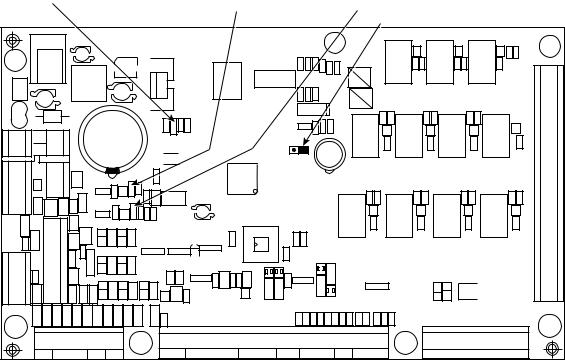
Main Base Board (MBB) — See Fig. 20. The MBB is the heart of the ComfortLink control system. It contains the major portion of operating software and controls the operation of the machine. The MBB continuously monitors input/output channel information received from its inputs and from all other modules. The MBB receives inputs from the discharge and suction pressure transducers, current sensor boards (CSB) and thermistors. See Table 3. The MBB also receives the discrete inputs from the thermostat contacts and other status switches. See Table 4. The MBB also controls several outputs. Information is transmitted between modules via a 3-wire communication bus or LEN (Local Equipment Network). The CCN (Carrier Comfort Network®) bus is also supported. Connections to both LEN and CCN buses are made at the LVT (low voltage terminal) terminal strip.
Current Sensor Board (CSB) — The CSB is used to monitor the status of the compressors by measuring current and providing an analog input to the main base board (MBB) or compressor expansion module (CXB).
Energy Management Module (EMM) — The EMM module is available as a factory-installed option or as a fieldinstalled accessory. The EMM module receives 4 to 20 mA inputs for the percent capacity, temperature reset, cooling set point, and demand limit functions. The EMM module also receives the switch inputs for the field-installed 2-stage demand limit and when two thermostats are used for one unit. The EMM module communicates the status of all inputs with the MBB, and the MBB adjusts the control point, capacity limit, and other functions according to the inputs received.
Table 2 — Scrolling Marquee Display Menu Structure*
MODE |
RUN |
SERVICE |
TEMPERATURES |
PRESSURES |
SET |
INPUTS |
OUTPUTS |
CONFIGURATION |
TIME |
OPERATING |
ALARMS |
STATUS |
TEST |
POINTS |
CLOCK |
MODES |
|||||||
|
Auto |
Manual |
Unit |
Ckt A |
|
Unit |
Unit |
|
|
|
|
|
Mode |
Cooling |
Display |
Unit Time |
Modes |
Current |
|||||
|
Display |
Temperatures |
Pressures |
Discrete |
Discrete |
||||||
|
On/Off |
(COOL) |
(DISP) |
(TIME) |
(MODE) |
(CRNT) |
|||||
|
(VIEW) |
(UNIT) |
(PRC.A) |
(GEN.I) |
(GEN.O) |
||||||
|
(TEST) |
|
|
|
|
|
|||||
|
|
|
|
|
|
|
|
|
|
|
|
|
Machine |
Unit |
Ckt A |
Ckt B |
Head |
Ckt A/B |
Ckt A |
Unit Configuration |
Unit Date |
Task State |
Reset |
|
Hours/Starts |
Outputs |
Temperatures |
Pressures |
Pressure |
Alarms |
|||||
|
(CRCT) |
(CIR.A) |
(UNIT) |
(DATE) |
(TSKS) |
||||||
|
(RUN) |
(OUTS) |
(CIR.A) |
(PRC.B) |
(HEAD) |
(RCRN) |
|||||
|
|
|
|
|
|
||||||
|
Compressor |
Ckt A Comp |
Ckt B |
|
|
Unit |
|
|
Daylight |
|
Alarm |
|
|
|
Ckt B |
CCN Network |
Saving |
|
|||||
|
Run Hours |
Tests |
Temperatures |
|
|
Analog |
|
History |
|||
|
|
|
(CIR.B) |
(CCN) |
Time |
|
|||||
|
(HOUR) |
(CMPA) |
(CIR.B) |
|
|
(4-20) |
|
(HIST) |
|||
|
|
|
|
|
(DST) |
|
|||||
|
|
|
|
|
|
|
|
|
|
|
|
|
Compressor |
Ckt B Comp |
|
|
|
|
|
|
Local |
|
|
|
|
|
|
|
|
Options 1 |
Holiday |
|
|
||
|
Starts |
Tests |
|
|
|
|
|
|
|
||
|
|
|
|
|
|
(OPT1) |
Schedules |
|
|
||
|
(STRT) |
(CMPB) |
|
|
|
|
|
|
|
||
|
|
|
|
|
|
|
(HOL.L) |
|
|
||
|
|
|
|
|
|
|
|
|
|
|
|
|
Preventive |
|
|
|
|
|
|
Options 2 |
Schedule |
|
|
SUB-MODE |
Maintenance |
|
|
|
|
|
|
Number |
|
|
|
|
|
|
|
|
|
(OPT2) |
|
|
|||
|
(PM) |
|
|
|
|
|
|
(SCH.N) |
|
|
|
|
|
|
|
|
|
|
|
|
|
||
|
Software |
|
|
|
|
|
|
|
Local |
|
|
|
|
|
|
|
|
|
Motormaster |
Schedule |
|
|
|
|
Version |
|
|
|
|
|
|
|
|
||
|
|
|
|
|
|
|
(M.MST) |
Number |
|
|
|
|
(VERS) |
|
|
|
|
|
|
|
|
||
|
|
|
|
|
|
|
|
(SCH.L) |
|
|
|
|
|
|
|
|
|
|
|
|
|
|
|
|
|
|
|
|
|
|
|
Reset Cool |
Schedule |
|
|
|
|
|
|
|
|
|
|
Temperature |
Overide |
|
|
|
|
|
|
|
|
|
|
(RSET) |
(OVR) |
|
|
|
|
|
|
|
|
|
|
Set Point Select |
|
|
|
|
|
|
|
|
|
|
|
(SLCT) |
|
|
|
|
|
|
|
|
|
|
|
Service |
|
|
|
|
|
|
|
|
|
|
|
Configuration |
|
|
|
|
|
|
|
|
|
|
|
(SERV) |
|
|
|
|
|
|
|
|
|
|
|
Broadcast |
|
|
|
|
|
|
|
|
|
|
|
Configuration |
|
|
|
|
|
|
|
|
|
|
|
(BCST) |
|
|
|
LEGEND |
|
|
|
|
|
|
|
|
|
|
|
Ckt — Circuit |
|
|
|
|
|
|
|
|
|
|
|
*Throughout this text, the location of items in the menu structure will be described in |
|
|
|
|
|
|
|||||
the following format: |
|
|
|
|
|
|
|
|
|
|
|
Item Expansion (Mode Name Sub-mode Name ITEM) |
|
|
|
|
|
|
|
|
|||
18
RED LED - STATUS |
GREEN LED - |
YELLOW LED - |
|
LEN (LOCAL EQUIPMENT NETWORK) |
CCN (CARRIER COMFORT NETWORK) |
INSTANCE JUMPER
|
|
CEPL130346-01 |
|
|
|
|
|
|
K11 |
K10 |
K9 |
J1 |
J2 |
K8 |
K7 |
K6 |
K5 |
STATUS |
|
|
|
||
J4 |
J3 |
LEN |
|
|
J10 |
|
|
|
|
||
|
|
|
|
|
|
|
|
K4 |
K3 |
K2 |
K1 |
|
|
CCN |
|
|
|
|
J5 |
|
|
|
|
J6 |
|
|
|
|
|
|
J7 |
J8 |
|
|
J9 |
Fig. 20 — Main Base Board
Table 3 — Thermistor Designations
THERMISTOR INPUT |
PIN CONNECTION POINT |
|
Return Air (Accessory) |
MBB J8-11,12; LVT 19,20 |
|
Supply Air (Accessory) |
MBB J8-12,13; LVT 11,19 |
|
Compressor Return Gas |
MBB J8-1,2 |
|
Temperature A |
||
|
||
Compressor Return Gas |
MBB J8-3,4 |
|
Temperature B |
||
|
||
Outdoor Air Temperature |
MBB J8-7,8 |
|
Discharge Temperature |
AUX J6-1,2 |
|
(Digital Option Only) |
||
|
||
Space Temperature (Accessory) |
MBB J8-5,6; LVT 21,22 |
|
Table 4 — Switch Inputs |
||
SWITCH INPUT |
PIN CONNECTION POINT |
Thermostat Y1 (Accessory) |
LVT 12,18 |
Thermostat Y2 (Accessory) |
LVT 15,18 |
Fan Status 1 (Accessory) |
LVT 16,18 |
Fan Status 2 (Accessory) |
LVT 17,18 |
Remote On/Off |
LVT 13,14 |
High Pressure Switch A |
MBB J6-4 |
High Pressure Switch B |
MBB J6-6 |
Compressor Expansion Module (CXB) — The CXB is only used on unit sizes 070-100 to provide additional inputs and outputs for fans and compressors when the unit has more than 4 compressors.
AUX Board (AUX) — The AUX is used with the digital scroll option and the low ambient head pressure option. It provides additional inputs and outputs for digital scroll control along with analog outputs to control head pressure control fan speeds.
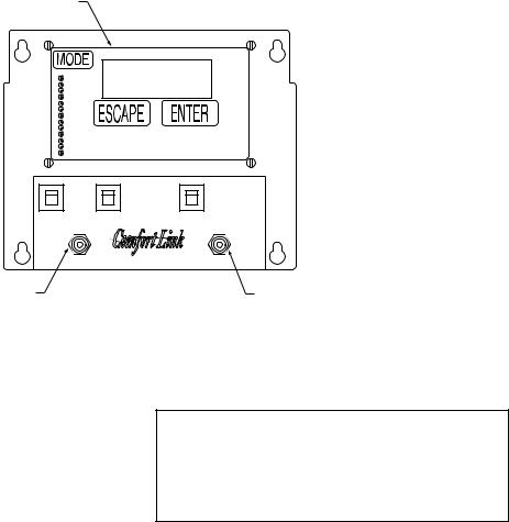
Enable/Off/Remote Contact Switch — The Enable/ Off/Remote Contact switch is a 3-position switch used to control the unit. When switched to the Enable position, the unit is under its own control. Move the switch to the Off position to shut the unit down. Move the switch to the Remote Contact position and a field-installed dry contact can be used to start the unit. The contacts must be capable of handling a 24 vac, 50 mA load. In the Enable and Remote Contact (dry contacts closed)
positions, the unit is allowed to operate and respond to the scheduling configuration, CCN configuration and set point data. See Fig. 21.
Emergency On/Off Switch — The Emergency On/Off switch should only be used when it is required to shut the unit off immediately. Power to the MBB, CXB, AUX, EMM, and scrolling marquee display is interrupted when this switch is off and all outputs from these modules will be turned off.
Board Addresses — The main base board (MBB) has a 3-position Instance jumper that must be set to ‘1.’ All other boards have 4-position DIP switches. All switches are set to ‘On’ for all boards.
Control Module Communication
RED LED — Proper operation of the control boards can be visually checked by looking at the red status LEDs (light-emitting diodes). When operating correctly, the red status LEDs should be blinking in unison at a rate of once every 2 seconds. If the red LEDs are not blinking in unison, verify that correct power is being supplied to all modules. Be sure that the main base board (MBB) is supplied with the current software. If necessary, reload current software. If the problem still persists, replace the MBB. A red LED that is lit continuously or blinking at a rate of once per second or faster indicates that the board should be replaced.
GREEN LED — The MBB has one green LED. The Local Equipment Network (LEN) LED should always be blinking whenever power is on. All other boards have a LEN LED which should be blinking whenever power is on. Check LEN connections for potential communication errors at the board J3 and/or J4 connectors. Communication between modules is accomplished by a 3-wire sensor bus. These 3 wires run in parallel from module to module. The J4 connector on the MBB provides both power and communication directly to the marquee display only.
YELLOW LED — The MBB has one yellow LED. The Carrier Comfort Network (CCN) LED will blink during times of network communication.
19
SCROLLING MARQUEE
DISPLAY
|
CB1 REMOTE CB2 |
CB3 |
|
|
CONTROL |
OFF |
|
|
SW1 |
OFF |
SW2 |
LEGEND |
ENABLE |
ON |
|
|
|
|
|
CB — Circuit Breaker |
ENABLE/OFF/REMOTE |
|
EMERGENCY |
SW — Switch |
|
||
|
CONTACT SWITCH |
|
ON-OFF SWITCH |
Fig. 21 — Scrolling Marquee, Enable/Off/Remote Contact Switch, and Emergency On/Off Switch Locations
Carrier Comfort Network® (CCN) Interface —
The 38AP units can be connected to the CCN if desired. The communication bus wiring is a shielded, 3-conductor cable with drain wire and is supplied and installed in the field. See Table 5. The system elements are connected to the communication bus in a daisy chain arrangement. The positive pin of each system element communication connector must be wired to the positive pins of the system elements on either side of it. This is also required for the negative and signal ground pins of each system element. Wiring connections for CCN should be made at LVT. Consult the CCN Contractor’s Manual for further information.
NOTE: Conductors and drain wire must be 20 AWG (American Wire Gage) minimum stranded, tinned copper. Individual conductors must be insulated with PVC, PVC/nylon, vinyl, Teflon, or polyethylene. An aluminum/polyester 100% foil shield and an outer jacket of PVC, PVC/nylon, chrome vinyl, or Teflon with a minimum operating temperature range of –20 C to 60 C is required. Wire manufactured by Alpha (2413 or 5463), American (A22503), Belden (8772), or Columbia (02525) meets the above mentioned requirements.
It is important when connecting to a CCN communication bus that a color coding scheme be used for the entire network to simplify the installation. It is recommended that red be used for the signal positive, black for the signal negative, and white for the signal ground. Use a similar scheme for cables containing different colored wires.
At each system element, the shields of its communication bus cables must be tied together. If the communication bus is entirely within one building, the resulting continuous shield must be connected to a ground at one point only. If the communication bus cable exits from one building and enters another, the shields must be connected to grounds at the lightning suppressor in each building where the cable enters or exits the building (one point per building only). To connect the unit to the network:
1.Turn off power to the control box.
2.Cut the CCN wire and strip the ends of the red (+), white (ground), and black (–) conductors. (Substitute appropriate colors for different colored cables.)
3.Connect the red wire to (+) terminal on LVT of the plug, the white wire to COM terminal, and the black wire to the
(–) terminal.
4.The RJ14 CCN connector on LVT can also be used, but is only intended for temporary connection (for example, a laptop computer running Service Tool).
IMPORTANT: A shorted CCN bus cable will prevent some routines from running and may prevent the unit from starting. If abnormal conditions occur, unplug the connector. If conditions return to normal, check the CCN connector and cable. Run new cable if necessary. A short in one section of the bus can cause problems with all system elements on the bus.
Table 5 — CCN Communication Bus Wiring
MANUFACTURER |
PART NO. |
||
Regular Wiring |
Plenum Wiring |
||
|
|||
Alpha |
1895 |
— |
|
American |
A21451 |
A48301 |
|
Belden |
8205 |
884421 |
|
Columbia |
D6451 |
— |
|
Manhattan |
M13402 |
M64430 |
|
Quabik |
6130 |
— |
|
OPERATING DATA
Sensors — The electronic control uses 3 to 7 thermistors to sense temperatures for controlling unit operation. See Table 3. These sensors are outlined below. Three different thermistor curves are utilized depending on the thermistor and the configuration of the input. The three different types are 5 k at 77 F (25 C), 10 k at 77 F (25 C), and 86 k at 77 F (25 C). See Thermistors section on page 49 for additional information.
RETURN AIR TEMPERATURE (RAT) ACCESSORY (Part No. 33ZCSENSAT) — A return air temperature sensor is required for unit sizes 040-100 and all units equipped with the digital scroll option. The sensor is field installed in the indoor unit and wired to the LVT of the unit to measure the air temperature entering the evaporator coil. The sensor should be located directly in front of the evaporator coil after an outside air intake.
The RAT sensor consists of a thermistor encased within a stainless steel probe. See Fig. 22. The sensor probe is 6 in. nominal length with 114 in. of unshielded, 2-conductor 18 AWG twisted-pair cables. The sensor temperature range is –40 to 245 F with a nominal resistance of 10,000 ohms at 77 F. The sensor has with an accuracy of ±0.36 F.
20
3.90
3.00
.175 DIA x .600
.08
.39
FOAM GASKET
.40'' O.D.
 .250 ±.01 Dia
5.5 ±.5
PLENUM RATED CABLE |
NOTE: All dimensions |
114'' ±6 |
shown in inches. |
Fig. 22 — 33ZCSENSAT Sensor
SUPPLY AIR TEMPERATURE (SAT) ACCESSORY (33ZCSENSAT) — A supply air temperature sensor is required for unit sizes 040-100 and all units equipped with the digital scroll option. The SAT sensor consists of a thermistor encased within a stainless steel probe. See Fig. 22. The SAT sensor probe is 6 in. nominal length with 114 in. of unshielded, 2-conductor 18 AWG twisted-pair cables. The sensor temperature range is –40 to 245 F with a nominal resistance of 10,000 ohms at 77 F. The sensor has an accuracy of ±0.36 F.
NOTE: The sensor must be mounted in the discharge of the unit, downstream of the cooling coil and before any heating coil or heat exchanger if reheat is utilized. Be sure the probe tip does not come in contact with any of the unit surfaces.
COMPRESSOR RETURN GAS TEMPERATURE SENSOR (RGT) — These sensors are factory installed in a friction fit well located in the suction line of each circuit. They are a 5 k thermistor connected to the main base board.
OUTDOOR-AIR TEMPERATURE SENSOR (OAT) — This sensor is factory installed on a bracket which is inserted through the base pan of the unit on the unit sizes 025-060 and mounted to the back of the control box on the unit sizes 070100. This sensor is a 5 k thermistor connected to the main base board.
DISCHARGE TEMPERATURE THERMISTOR (DTT) — This sensor is only used on units with a digital compressor. The sensor is mounted on the discharge line close to the discharge of the digital compressor. It attaches to the discharge line using a spring clip and protects the system from high discharge gas temperature when the digital compressor is used. This sensor is a 86 k thermistor connected to the AUX board.
SPACE TEMPERATURE SENSOR (SPT) — The space temperature sensors are used to measure the interior temperature of a building. The following three types of SPT sensors are available:
•Space temperature sensor (33ZCT55SPT) with timed override button (see Fig. 23)
•Space temperature sensor (33ZCT56SPT) with timed override button and set point adjustment (see Fig. 24)
•Space temperature sensor (33ZCT59SPT) with occupancy override button, set point adjustment slidebar, and LCD (liquid crystal display) display
1 |
2 |
3 |
4 |
5 |
6 |
RED(+) |
|
|
|
|
|
|
WHT(GND) |
CCN COM |
|
|
|
|
|
|
|
BLK(-) |
|
|
|
|
|
|
|
|
|
|
|
|
SEN |
|
|
|
|
|
SW1 |
|
|
|
|
|
|
|
|
|
|
|
BRN (GND) |
SENSOR WIRING |
|
|
|
|
|
|
BLU (SPT) |
|
|
Fig. 23 — Space Temperature Sensor
Typical Wiring (33ZCT55SPT)
1 |
2 |
3 |
4 |
5 |
6 |
RED(+) |
|
|
|
|
|
|
WHT(GND) |
CCN COM |
|
|
|
|
|
|
|
BLK(-) |
|
|
|
|
|
|
|
|
|
|
|
|
SEN |
|
SET |
|
|
|
SW1 |
|
|
|
|
BLK |
|
|
|
|
|
|
|
|
|
|
|
|
|
|
|
(T56) |
|
|
|
|
|
|
BRN (GND) |
SENSOR WIRING |
|
|
|
|
|
|
BLU (SPT) |
|
|
|
|
|
|
|
|
|
JUMPER |
|
|
|
|
|
|
|
TERMINALS |
|
|
|
|
|
|
|
AS SHOWN |
Cool Warm
Fig. 24 — Space Temperature Sensor
Typical Wiring (33ZCT56SPT)
The sensor should be mounted approximately 5 ft from the floor in an area representing the average temperature in the space. Allow at least 4 ft between the sensor and any corner. Mount the sensor at least 2 ft from an open doorway.
To connect the space temperature sensor (Fig. 25):
1.Use a 20 gage wire to connect the sensor to the controller. The wire is suitable for distances of up to 500 ft. Use a three-conductor shielded cable for the sensor and set point adjustment connections. The standard CCN communication cable may be used. If the set point adjustment (slidebar) is not required, then an unshielded, 18 or 20 gage, two-conductor, twisted pair cable may be used. Connect one wire of the twisted pair to one SEN terminal and connect the other wire to the other SEN terminal located under the cover of the space temperature sensor.
2.Connect the other ends of the wires to terminals 21 and 22 on LVT located in the unit control box.
3.Connect the T56 set point adjustment between the SET terminal and LVT terminal 23.
21
Units on the CCN can be monitored from the space using the RJ11 connector provided with the space sensor, if desired. To wire the RJ11 connector into the CCN (Fig. 26):
IMPORTANT: The cable selected for the RJ11 connector wiring MUST be identical to the CCN communication bus wire used for the entire network. Refer to Table 5 for acceptable wiring.
1.Cut the CCN wire and strip ends of the red (+), white (ground), and black (–) conductors. (If another wire color scheme is used, strip ends of appropriate wires.)
2.Insert and secure the red (+) wire to terminal 5 of the space temperature sensor terminal block.
3.Insert and secure the white (ground) wire to terminal 4 of the space temperature sensor.
4.Insert and secure the black (–) wire to terminal 2 of the space temperature sensor.
5.Connect the other end of the communication bus cable to the remainder of the CCN communication bus.
NOTE: See Fig. 27 for space temperature averaging.
|
SPT |
|
SENSOR |
SEN |
LVT |
SEN |
|
|
21 |
|
22 |

 SET
SET

 23
23
Fig. 25 — Typical SPT Wiring
|
|
T-55 SPACE |
|
|
SENSOR |
|
|
6 |
|
CCN+ |
5 |
TO CCN |
CCN GND |
4 |
COMM 1 |
|
|
BUS (PLUG) |
|
3 |
AT UNIT |
|
|
|
CCN- |
2 |
|
|
1 |
Fig. 26 — CCN Communications Bus Wiring to Optimal Space Sensor RJ11 Connector
|
|
RED |
RED |
|
|
|
BLK |
BLK |
|
J6 |
RED |
RED |
RED |
|
6 |
||||
|
|
|
||
7 |
BLK |
BLK |
BLK |
|
|
|
|
SENSOR 1 |
SENSOR 2 |
SENSOR 3 |
|
SPACE TEMPERATURE AVERAGING — 4 SENSOR APPLICATION |
|||
J6 |
|
RED |
RED |
RED |
|
||
6 |
|
|
|
BLK |
|
BLK |
BLK |
7 |
|
|
|
BLK |
RED |
SENSOR 1 |
SENSOR 2 |
|
|
||
|
|
RED |
RED |
|
|
BLK |
BLK |
BLK |
RED |
SENSOR 4 |
SENSOR 5 |
|
|
||
LEGEND |
|
RED |
RED |
Factory Wiring |
|
BLK |
BLK |
|
|
|
|
Field Wiring |
|
|
|
|
|
SENSOR 7 |
SENSOR 8 |
SPACE TEMPERATURE AVERAGING — 9 SENSOR APPLICATION
Fig. 27 — Space Temperature Averaging
SENSOR 4
SENSOR 3
SENSOR 6
SENSOR 9
22

Fan Status Input — A proof-of-fan operation is recommended and needs to be field installed in the indoor unit. Several different types of switches can be utilized, such as a differential pressure switch located across the indoor fan or auxiliary contacts on an indoor fan contactor.
Thermostat Input — A two-stage thermostat can be used for constant volume applications to provide Y1 and Y2 cooling inputs.
Pressure Transducer Inputs — Each refrigerant circuit is equipped with a suction and discharge pressure transducer. The suction pressure transducers have a yellow body with a pressure range of -6.7 to 420 psig while the discharge transducers have a red body with a pressure range of 14.5 to 667 psig. These inputs connect to the MBB (main base board) and are used to monitor the status of the unit and to ensure the unit operates within the compressor envelope. The transducers are used to protect the compressor from operating at too low or too high of a pressure condition. In some cases, the unit may not be able to run at full capacity. The MBB will automatically reduce the capacity of a circuit as needed to maintain specified maximum/minimum operating pressures.
Energy Management Module (Fig. 28) — The energy management module (EMM) is a factory-installed option (FIOP) or field-installed accessory used for the following types of temperature reset, demand limit, and capacity control features:
•4 to 20 mA temperature reset
•4 to 20 mA cooling set point
•4 to 20 mA desired capacity set point
•4 to 20 mA demand limit
•Discrete inputs for 2-step demand limit (requires fieldsupplied dry contacts capable of handling a 24 vac, 50 mA load)
•Discrete inputs for units with dual thermostats
NOTE: A field-supplied 4 to 20 mA signal generator is required for use with the EMM.
See VAV Supply Air Temperature Reset and Demand Limit sections on pages 29 and 31 for further details.
 CAUTION
Care should be taken when interfacing with other manufacturer’s control systems due to possible power supply differences, full wave bridge versus half wave rectification. The two different power supplies cannot be mixed. ComfortLink™ controls use half wave rectification. A signal isolation device should be utilized if a full wave bridge signal generating device is used.
Control — When mechanical cooling is required, the MBB has the capability to control the unit capacity by staging multiple scroll compressors and controlling the digital scroll compressor operation. The control also checks on various other operation parameters in the unit to make sure that safeties are not exceeded and the compressors are reliably operated.
The ComfortLink™ control system offers two basic control approaches to mechanical cooling; constant volume operation for 2 stages of cooling or VAV operation for multiple stages of cooling. In addition to these methods of control, the ComfortLink control offers the ability to run multiple stages of cooling for either a space temperature sensor or thermostat control by controlling the unit to either a low or high cool set point. The control type Configuration OPT2 C.TYP determines the selection of the type of cooling control as well as the method for selecting a cooling mode.
SETTING UP THE SYSTEM
Machine Control Type (Configuration OPT2 C.TYP)
— The most important cooling control configuration is located under Configuration OPT2. This configuration defines the method and control source responsible for selecting a cooling mode. The configuration also determines the method by which compressors are staged. Control types are:
•C.TYP = 1 (VAV-RAT) configuration refers to standard VAV operation.
|
CEBD430351-0396-01C |
|
|
|
|
PWR |
J1 |
J2 |
|
|
01 |
|
|
|
|
||
|
|
|
|
|
- |
J4 |
|
J3 |
LEN |
|
CEPL130351 |
|
|
STATUS |
|
TEST 1 |
|
|
|
|
|
||
J5 |
|
|
|
|
|
|
|
|
|
J7 |
|
|
|
J6 |
|
TEST 2 |
|
|
|
RED LED - STATUS |
GREEN LED - |
ADDRESS |
|
|
|
LEN (LOCAL EQUIPMENT NETWORK) |
DIP SWITCH |
|
|
Fig. 28 — Energy Management Module
23
•C.TYP = 3 (TSTAT-MULTI) configuration will force the MBB to monitor the thermostat inputs to make a determination of mode. Unlike traditional 2-stage thermostat control, the unit is allowed to use multiple stages of cooling control and perform VAV style operation. The control will be able to call out a low set point or a high set point to maintain supply air temperature. (Required for 025-030 units with digital scroll option and 040-100 units with two-stage thermostat control.)
•C.TYP = 4 (TSTAT-2STG) configuration will force the MBB to monitor the thermostat inputs to make a determination of mode.
•C.TYP = 5 (SPT-MULTI) configuration will force the MBB to monitor a space temperature sensor to make a determination of mode. Unlike traditional 2-stage space temperature control, the unit is allowed to use multiple stages of cooling control and perform VAV style operation. The control will be able to call out a low set point or a high set point to maintain supply air temperature.
•C.TYP = 7 (% CAPACITY) configuration will force the MBB to monitor the 4-20 cooling demand CL.MA input and translate this into desired % capacity for the unit.
•C.TYP = 9 (VAV-SETPOINT) configuration will force the MBB to monitor the 4-20 cooling demand CL.MA input. This value will be translated into a desired leav- ing-air set point ranging from 40 to 80 F. The control will translate the input linearly with 4 ma equal to 40 F set point and 20 mA equal to 80 F set point.
Unit Capacity Control Based on Unit Type — The MBB uses several set points to control capacity depending on unit type. The set points are located in the set point area of the display SetPoints COOL. Refer to Table 6 and the following descriptions.
Table 6 — Unit Capacity Control
ITEM |
DESCRIPTION |
RANGE |
UNITS |
DEFAULT |
CSP1 |
Cooling Set Point 1 |
40-80 |
F |
65 |
CSP2 |
Cooling Set Point 2 |
40-80 |
F |
55 |
SPS.P |
Space Temperature Cooling Set |
65-80 |
F |
74 |
|
Point |
|
|
|
L.C.ON |
Demand Level Low Cool On |
–1-2 |
^F |
1.5 |
H.C.ON |
Demand Level (+) High Cool On |
0.5-20.0 |
^F |
0.5 |
L.C.OF |
Demand Level (–) Low Cool Off |
0.5-2 |
^F |
1 |
•C.TYP = 1 (VAV-RAT) is a capacity control routine that controls compressor capacity to supply air temperature. The MBB will attempt to control leaving temperature to the control point (CTPT) which equals CSP1 plus any reset which is being applied.
•C.TYP = 3 (TSTAT-MULTI) configuration will force the MBB to monitor the thermostat inputs to make a determination of control point (CTPT). The control will vary the control point based on Y1 and Y2 inputs. When Y1 is closed CSP1 will be used and when Y2 is closed CSP2 will be used as the supply air temperature set point. CSP1 should be greater than CSP2.
•C.TYP = 4 (TSTAT-2STG) configuration will force the MBB to monitor the thermostat inputs to make a determination of mode and capacity. If Y1 input is closed, 50% of the unit capacity will be energized and if Y2 is closed, 100% of the unit capacity will be energized.
NOTE: This is not a preferred method of control for units with greater than 2 stages of capacity
•C.TYP = 5 (SPT-MULTI) configuration will force the MBB to monitor the thermostat inputs to determine mode and cooling set point as the unit is controlled by space temperature vs space temperature set point SPS.P. Unlike traditional 2-stage thermostat control, the unit is allowed to use multiple stages of cooling control and perform VAV style operation. The control will be able to call out a low set point (CSP1) or high set point (CSP2) for
supply air depending on space temperature vs space temperature set point. The control uses SPS.P, LC.ON, HC.ON, and LC.OF to determine the leaving set point. LC.ON and HC.ON are added to the space temperature set point to determine when cooling mode will begin and when CSP1 and CSP2 will be used for leaving set point.
Based on LC.OF, the control point transitions between CSP1 and CSP2. LC.OF is used to calculate the space temperature at which control point is raised based on space temperature vs space temperature set point (SPS.P) plus LC.ON minus LC.OF. The control point transition from CSP2 to CSP1 occurs when space temperature is below LC.OF divided by 2.
For example (see Fig. 29):
Given: SPS.P = 72 F, LC.ON = 1, HC.ON = 3, LC.OF = 2 F, CSP1 = 60 F, and CSP2 = 55 F
If space temperature equals 73 F (72+1) (Low Cool) cooling will begin and control set point equals 60 F (CSP1).
If space temperature is greater than 76 F (72+1+3 = 76) (High Cool), control point set point would equal 55 F (CSP2).
If space temperature falls below 72 F (73-2/2) (Low Cool minus LC.OF/2), control point transitions back to 60 F CSP1 if space continues to fall below 71 F (73-2) (Low Cool minus LC.OF), the unit is shut off.
76 F |
|
|
|
|
|
|
|
Hi Cool Start |
|||||
|
|
|
|
|
|
|
|||||||
|
|
|
|
|
|
|
|
|
|||||
|
|
|
H.C.ON |
|
|
|
|
|
|
||||
73 F |
|
|
|
|
|
|
|
Lo Cool Start |
|||||
L.C.ON |
|
L.C. OF |
L.C. OF/2 |
|
|
|
|
||||||
|
|
|
|
||||||||||
|
|
|
|
|
|
|
|
|
|
||||
72 F |
|
|
|
|
|
|
|
Hi Cool End 72 F |
|||||
|
|
|
|
|
|
|
|||||||
|
|
|
|
|
|
|
|
|
|
|
|
|
|
|
Cooling Setpoint |
|
|
|
|
|
|||||||
|
|
|
|
|
|
|
|
|
Lo Cool End 71 F |
|
A48-7701 |
||
|
|
|
|
|
|
|
|
|
|
||||
|
|
|
|
|
|
|
|
|
|
||||
Fig. 29 — Space Temperature vs.
Space Temperature Set Point
•C.TYP = 7 (% CAPACITY) configuration will force the MBB to monitor the input 4-20 cooling demand CL.MA and translate this into desired % capacity for the unit. The control will attempt to match the desired capacity insuring the unit operates the compressor within compressor safeties and timeguards. (Requires the EMM option or accessory.)
•C.TYP = 9 (VAV-SETPOINT) configuration will force the MBB to operate as a VAV unit and control capacity to meet supply air temperature. The control point is developed from the 4-20 cooling demand CL.MA input value. The 4 to 20 mA input will be translated into a desired control point ranging from 40 to 80 F. The control will translate the input linearly with 4 mA equal to 40 F set point and 20 mA equal to 80 F set point. (Requires the EMM option or accessory.)
Capacity Control Logic when Control is Controlling to Supply Temperature — The control system cycles compressors, hot gas bypass and the digital compressor to maintain the supply temperature at or close to the control point of the unit. The SAT and RAT sensors are used by the main base board (MBB) to determine the temperature drop across the evaporator and are used in determining the optimum time to add or subtract capacity stages. The CSP set points can be automatically reset by
24
the return temperature, space, or outdoor-air temperature reset features. It can also be reset from an external 4 to 20 mA signal (requires energy management module factory-installed option or field-installed accessory).
The control has an automatic lead-lag feature built in which determines the wear factor (combination of starts and run hours) for each compressor. If all compressors are off and less than 30 minutes has elapsed since the last compressor was turned off, the wear factor is used to determine which compressor to start next. As additional stages of compression are required, the processor control will add them. If a circuit is to be stopped, the compressor with the lowest wear factor will be shut off first. See Table 7 for compressor size information and Table 8 for compressor loading sequence.
The capacity control algorithm runs every 30 seconds. The algorithm attempts to maintain the control point at the desired set point. Each time it runs, the control reads the entering and leaving temperatures. The control determines the rate at which conditions are changing and calculates 2 variables based on these conditions. Next, a capacity ratio is calculated using the 2 variables to determine whether or not to make any changes to the current stages of capacity. This ratio value ranges from –100 to +100%. If the next stage of capacity is a compressor, the control starts (stops) a compressor when the ratio reaches +100% (-100%). A delay of 90 seconds occurs after each capacity step change. Refer to Table 8.
Table 7 — Compressor Size Information
UNIT SIZE |
|
CIRCUIT A (Nominal hp) |
|
|
CIRCUIT B (Nominal hp) |
|
||||
Compressor A1 |
|
Compressor A2 |
|
Compressor A3 |
Compressor B1 |
|
Compressor B2 |
|
Compressor B3 |
|
|
|
|
|
|
||||||
38APS025 |
11 |
|
11 |
|
— |
— |
|
— |
|
— |
38APD025 |
11 |
|
— |
|
— |
11 |
|
— |
|
— |
38APS027 |
13 |
|
13 |
|
— |
— |
|
— |
|
— |
38APD027 |
13 |
|
— |
|
— |
13 |
|
— |
|
— |
38APS030 |
15 |
|
15 |
|
— |
— |
|
— |
|
— |
38APD030 |
15 |
|
— |
|
— |
15 |
|
— |
|
— |
38APS040 |
13 |
|
13 |
|
13 |
— |
|
— |
|
— |
38APD040 |
10 |
|
10 |
|
— |
9 |
|
9 |
|
— |
38APS050 |
15 |
|
15 |
|
15 |
— |
|
— |
|
— |
38APD050 |
12 |
|
12 |
|
— |
13 |
|
13 |
|
— |
38APD060 |
13 |
|
13 |
|
— |
15 |
|
15 |
|
— |
38APD070 |
15 |
|
15 |
|
— |
11 |
|
11 |
|
11 |
38APD080 |
15 |
|
15 |
|
— |
15 |
|
15 |
|
15 |
38APD090 |
13 |
|
13 |
|
13 |
15 |
|
15 |
|
15 |
38APD100 |
15 |
|
15 |
|
15 |
15 |
|
15 |
|
15 |
Table 8 — Part Load Data Percent
38AP UNIT SIZE |
CONTROL |
LOADING SEQUENCE A |
LOADING SEQUENCE B |
|||
STEPS |
% Displacement |
Compressor |
% Displacement |
Compressor |
||
|
||||||
38APS025-030 |
1 |
50 |
A1 |
— |
— |
|
2 |
100 |
A1,A2 |
— |
— |
||
|
||||||
38APD025-030 |
1 |
50 |
A1 |
50 |
B1 |
|
|
2 |
100 |
A1, B1 |
100 |
A1,B1 |
|
38APS040,050 |
1 |
33 |
A1 |
— |
— |
|
2 |
67 |
A1,A2 |
— |
— |
||
|
3 |
100 |
A1,A2,A3 |
— |
— |
|
|
1 |
27 |
A1 |
23 |
B1 |
|
38APD040 |
2 |
50 |
A1,B1 |
50 |
A1,B1 |
|
|
3 |
77 |
A1,A2,B1 |
73 |
A1,B1,B2 |
|
|
4 |
100 |
A1,A2,B1,B2 |
100 |
A1,A2,B1,B2 |
|
|
1 |
23 |
A1 |
27 |
B1 |
|
38APD050,060 |
2 |
50 |
A1,B1 |
50 |
A1,B1 |
|
|
3 |
73 |
A1,A2,B1 |
77 |
A1,B1,B2 |
|
|
4 |
100 |
A1,A2,B1,B2 |
100 |
A1,A2,B1,B2 |
|
|
1 |
15 |
A1 |
15 |
B1 |
|
38APD070 |
2 |
42 |
A1,B1 |
42 |
A1,B1 |
|
3 |
57 |
A1,A2,B1 |
57 |
A1,B1,B2 |
||
|
4 |
85 |
A1,A2,B1,B2 |
85 |
A1,A2,B1,B2 |
|
|
5 |
100 |
A1,A2,B1,B2,B3 |
100 |
A1,A2,B1,B2,B3 |
|
|
1 |
20 |
A1 |
20 |
B1 |
|
38APD080 |
2 |
40 |
A1,B1 |
40 |
A1,B1 |
|
3 |
60 |
A1,A2,B1 |
60 |
A1,B1,B2 |
||
|
4 |
80 |
A1,A2,B1,B2 |
80 |
A1,A2,B1,B2 |
|
|
5 |
100 |
A1,A2,B1,B2,B3 |
100 |
A1,A2,B1,B2,B3 |
|
|
1 |
15 |
A1 |
18 |
B1 |
|
|
2 |
32 |
A1,B1 |
32 |
A1,B1 |
|
38APD090 |
3 |
48 |
A1,A2,B1 |
51 |
A1,B1,B2 |
|
4 |
66 |
A1,A2,B1,B2 |
66 |
A1,A2,B1,B2 |
||
|
||||||
|
5 |
82 |
A1,A2,A3,B1,B2,B3 |
85 |
A1,A2,B1,B2,B3 |
|
|
6 |
100 |
A1,A2,A3,B1,B2,B3 |
100 |
A1,A2,A3,B1,B2,B3 |
|
|
1 |
17 |
A1 |
17 |
B1 |
|
|
2 |
33 |
A1,B1 |
33 |
A1,B1 |
|
38APD100 |
3 |
50 |
A1,A2,B1 |
50 |
A1,B1,B2 |
|
4 |
67 |
A1,A2,B1,B2 |
67 |
A1,A2,B1,B2 |
||
|
||||||
|
5 |
83 |
A1,A2,A3,B1,B2 |
83 |
A1,A2,B1,B2,B3 |
|
|
6 |
100 |
A1,A2,A3,B1,B2,B3 |
100 |
A1,A2,A3,B1,B2,B3 |
|
NOTES:
1.These capacity steps may vary due to different capacity staging sequences.
2.When unit is equiped with digital scroll option, sequence A is always used.
25
MINUTES LEFT FOR START — This value is displayed only in the network display tables (using Service Tool, ComfortVIEW™ or ComfortWORKS® software) and represents the amount of time to elapse before the unit will start its initialization routine. This value can be zero without the machine running in many situations. This can include being unoccupied, ENABLE/OFF/REMOTE CONTACT switch in the OFF position, CCN not allowing unit to start, Demand Limit in effect, no call for cooling due to no load, and alarm or alert conditions present. If the machine should be running and none of the above are true, a minimum off time (DELY, see below) may be in effect. The machine should start normally once the time limit has expired.
MINUTES OFF TIME (Configuration OPT2
DELY) — This user-configurable time period is used by the control to determine how long unit operation is delayed after power is applied/restored to the unit. Typically, this time period is configured when multiple machines are located on a single site. For example, this gives the user the ability to prevent all the units from restarting at once after a power failure. A value of zero for this variable does not mean that the unit should be running.
NOTE: If the unit has digital scroll or hot gas bypass, circuit A is always lead.
LEAD/LAG DETERMINATION — This is a configurable choice and is factory set to be automatic for all units. The value can be changed to Circuit A or Circuit B leading as desired. Set at automatic, the control will sum the current number of logged circuit starts and one-quarter of the current operating hours for each circuit. The circuit with the lowest sum is started first. Changes to which circuit is the lead circuit and which is the lag are also made when total machine capacity is at 100% or when there is a change in the direction of capacity (increase or decrease) and each circuit’s capacity is equal.
CAPACITY CONTROL OVERRIDES — The following overrides will modify the normal operation of the routine.
Deadband Multiplier — The user configurable deadband multiplier (Configuration SLCT Z.GN) has a default value of 1.0. The range is from 1.0 to 4.0. When set to other than 1.0, this factor is applied to the capacity Load/Unload Factor. The larger this value is set, the longer the control will delay between adding or removing stages of capacity.
First Stage Override — If the current capacity stage is zero, the control will modify the routine with a 1.2 factor on adding the first stage to reduce cycling. This factor is also applied when the control is attempting to remove the last stage of capacity.
Slow Change Override — This control prevents the capacity stages from being changed when the supply temperature is
close to the set point (within an adjustable deadband) and moving toward the set point.
Ramp Loading — The ramp loading control (ConfigurationSLCT CRMP) limits the rate of change of supply temperature. If the unit is in a Cooling mode and configured for Ramp Loading, the control makes 2 comparisons before deciding to change stages of capacity. The control calculates a temperature difference between the control point and supply temperature. If the difference is greater than 4° F (2.2° C) and the rate of change (°F or °C per minute) is more than the configured Cooling Ramp Loading value (CRMP), the control does not allow any changes to the current stage of capacity.
Minimum Load Control — If equipped, the minimum load control valve is energized only when one compressor on the circuit is running and the unit is unloading.
Low Saturated Suction Protection — The control will try to prevent shutting a circuit down due to low saturated suction conditions by removing stages of capacity. See Alerts section.
Head Pressure Control — The main base board (MBB) controls the condenser fans to maintain the lowest condensing temperature possible, and thus the highest unit efficiency. The MBB uses the saturated condensing temperature input from the discharge pressure transducer and outside air temperature sensor to control the fans. If OAT is greater than 70 F before a circuit is starting, then all condenser fan stages will be energized. A fan stage is increased based on SCT. When the highest SCT of both circuits is greater than fan on set point, then an additional stage of fan will be added to the current fan stage. Fan On Set Point (F.ON) equals Head Set Point ON (115 F) except after a fan stage increase when Head Set Point is increased by Fan Stage Delta (10 F). A fan stage is decreased when the SCTs of both circuits are less than fan off set point for two minutes. Fan Off Set Point (F.OFF) equals Head Set Point OFF (–72 F). Table 9 shows the number of fan stages, contactors energized and the fans that are on during the fan stage. Unit sizes 025 to 060 have common fan control. Unit sizes 070 to 100 have some fans that are common and some that are controlled individually. Figure 30 shows the location of each fan and compressor within the unit.
MOTORMASTER® V OPTION — For low-ambient operation, the first stage of fans is equipped with the Motormaster V head pressure controller option or accessory. For units with common fans, the control will control the Head Pressure Setpoint (–10 F) and the highest SCT to try to maintain it at 100 F. Unit sizes 070 to 100 have one Motormaster V for each circuit and the control tries to maintain SCT at 100 F for the circuit. The controller is given an ON command with the first stage of fan and adjusts fan speed.
Table 9 — Fan Stages
38AP UNIT SIZE |
CIRCUIT A STAGES/COMMON FAN STAGES |
|
CIRCUIT B FAN STAGES |
|
||||
Fan Stage |
Contactor Energized |
Fans Operating |
Fan Stage |
|
Contactor Energized |
|
Fans Operating |
|
|
|
|
||||||
025-030 |
Stage 1 |
FC1 |
OFM1 |
— |
|
— |
|
— |
Stage 2 |
FC1,2 |
OFM1,2 |
|
|
||||
|
|
|
|
|
|
|||
040,050 |
Stage 1 |
FC1 |
OFM3 |
|
|
|
|
|
Stage 2 |
FC2 |
OFM1,2 |
— |
|
— |
|
— |
|
|
Stage 3 |
FC1,2 |
OFM1,2,3 |
|
|
|
|
|
|
Stage 1 |
FC1 |
OFM3 |
|
|
|
|
|
060 |
Stage 2 |
FC2 |
OFM1,2 |
— |
|
— |
|
— |
Stage 3 |
FC1,2 |
OFM1,2,3 |
|
|
||||
|
|
|
|
|
|
|||
|
Stage 4 |
FC1,2,3 |
OFM1,2,3,4 |
|
|
|
|
|
070 |
Stage 1* |
FC2,4 |
OFM1,2 |
Stage 1* |
|
FC1,3 |
|
OFM3,4 |
Stage 2 |
FC1 |
OFM3 |
Stage 2 |
|
FC2 |
|
OFM1 |
|
|
Stage 3 |
FC1,3 |
OFM3,4 |
Stage 3 |
|
FC2,4 |
|
OFM1,2 |
080 |
Stage 1 |
FC1 |
OFM5 |
Stage 1 |
|
FC4 |
|
OFM3 |
Stage 2 |
FC1,3 |
OFM5,6,(2) |
Stage 2 |
|
FC3,4 |
|
OFM3,2,(6) |
|
|
|
|
|
Stage 3 |
|
FC2,3,4 |
|
OFM3,1,2,(6) |
|
Stage 1 |
FC4 |
OFM3 |
Stage 1 |
|
FC4 |
|
OFM3 |
|
Stage 2 |
FC1 |
OFM5 |
Stage 2 |
|
FC2 |
|
OFM1 |
090,100 |
Stage 3 |
FC4,1 |
OFM3,5 |
Stage 3 |
|
FC4,2 |
|
OFM3,1 |
Stage 4 |
FC4,3 |
OFM3,(2),4,6 |
Stage 4 |
|
FC4,3 |
|
OFM3,2,4,(6) |
|
|
|
|
||||||
|
Stage 5 |
FC1,3 |
OFM5,(2),4,6 |
Stage 5 |
|
FC2,3 |
|
OFM1,2,4,(6) |
|
Stage 6 |
FC4,1,3 |
OFM3,5,(2),4,6 |
Stage 6 |
|
FC4,2,3 |
|
OFM3,1,2,4,(6) |
* Fan Stage 1 on unit size 070 is used only when ambient temperature is less than 32 F.
26
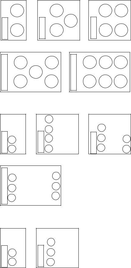
Outdoor Fan Layout – Top View
|
OFM1 |
|
|
OFM1 |
|
BOX |
|
|
BOX |
|
OFM3 |
CONTROL |
OFM2 |
|
CONTROL |
OFM2 |
|
|
|
|
|
||
Sizes 025-030 |
|
|
Sizes 040, 050 |
||
BOX |
OFM1 |
|
|
OFM5 |
BOX |
|
|
|
|
||
CONTROL |
|
OFM3 |
|
|
CONTROL |
|
|
|
|
|
|
|
OFM2 |
|
|
OFM6 |
|
Size 080
Compressor Layout Dual Circuit – Top View
|
|
|
A1 |
|
|
|
|
A2 |
|
BOX |
A1 |
BOX |
B1 |
|
CONTROL |
CONTROL |
|||
|
||||
B1 |
B2 |
|||
|
|
|||
Sizes 025-030 |
|
Sizes 040-060 |
||
BOX |
B1 |
A3 |
|
||
|
|
|
CONTROL |
B2 |
A2 |
|
||
|
|
|
|
B3 |
A1 |
|
|
Sizes 090, 100
|
OFM1 |
OFM3 |
BOX |
|
|
CONTROL |
OFM2 |
OFM4 |
|
Sizes 060, 070
OFM1 OFM3 OFM5
OFM2 OFM4 OFM6
Sizes 090, 100
|
B1 |
|
BOX |
B2 |
A2 |
CONTROL |
B3 |
A1 |
|
||
|
|
Sizes 070, 080
Compressor Layout Single Circuit – Top View
BOX |
A1 |
|
CONTROL |
||
A2 |
||
|
Sizes 025-030
CONTROL BOX
A1
A2
A3
Sizes 040, 050
Fig. 30 — Compressor and Fan Location
27
Service Test — Both main power and control circuit power must be on.
The Service Test function should be used to verify proper operation of condenser fan(s), compressors, minimum load valve solenoid (if installed), liquid line solenoid valve (if installed), and remote alarm relay. To use the Service Test mode, the Enable/Off/Remote Contact switch must be in the OFF position. Use the display keys and Service Test Mode and Sub-Mode Directory table in Appendix A to enter the mode and display TEST. Press ENTER twice so that OFF flashes. Enter the password if required. Use either arrow key to change the TEST value to the ON position and press ENTER . Place the Enable/Off/Remote Contact switch in the ENABLE position. The Service Test mode is now enabled. Press ESCAPE
and the |
down key to enter the OUTS, COMPA or COMPB |
sub-mode. |
|
Test the condenser fans, liquid line solenoid and alarm relay by changing the item values from OFF to ON. These discrete outputs are then turned off if there is no keypad activity for 10 minutes. When testing the digital output the display can be changed from 1 to 15 by using either the up or down arrow; the number represents the cycle rate out of a 15 second duty cycle that the output will be energized. If the cycle is set for 7, the output will be energized 7 seconds out of every 15 seconds. Test the compressor and minimum load valve solenoid (if installed) outputs in a similar manner. The minimum load valve solenoids will be turned off if there is no keypad activity for 10 minutes. Compressors will stay on until they are turned off by the operator. The Service Test mode will remain enabled for as long as there is one or more compressors running. All safeties are monitored during this test and they will turn a compressor, circuit or the machine off if required. Any other mode or sub-mode can be accessed, viewed, or changed during the TEST mode. The STAT item (Run/Status VIEW) will display "0" as long as the Service mode is enabled. The TEST sub-mode value must be changed back to OFF before the unit can be switched to Enable or Remote contact for normal operation.
Operating Modes
RAMP LOAD LIMITED (MD05) — Ramp load (pulldown) limiting is in effect. In this mode, the rate at which supply fluid temperature is dropped is limited to a predetermined value to prevent compressor overloading. See Cooling Ramp Loading (Configuration SLCT CRMP). The pull-down limit can be modified, if desired, to any rate from 0.2 to 2° F (0.1 to 1° C) per minute.
TIMED OVERRIDE IN EFFECT (MD06) — Timed override is in effect. This is a 1 to 4 hour temporary override of the programmed schedule, forcing unit to Occupied mode. Override can be implemented with unit under Local (Enable) or CCN (Carrier Comfort Network®) control. Override expires after each use.
SLOW CHANGE OVERRIDE (MD09) — Slow change override is in effect. The supply fluid temperature is close to and moving towards the control point.
MINIMUM OFF TIME ACTIVE (MD10) — Unit is being held off by Minutes Off Time (Configuration OPT2 DELY).
TEMPERATURE RESET (MD14) — Temperature reset is in effect. In this mode, unit is using temperature reset to adjust supply fluid set point upward and is currently controlling to the modified set point. The set point can be modified based on return fluid, outdoor-air-temperature, space temperature, or 4 to 20 mA signal.
DEMAND LIMITED (MD15) — Demand limit is in effect. This indicates that the capacity of the unit is being limited by
demand limit control option. Because of this limitation, the unit may not be able to produce the desired supply fluid temperature. Demand limit can be controlled by switch inputs or a 4 to 20 mA signal.
LOW TEMPERATURE COOLING (MD17) — Unit is in Cooling mode and the rate of change of the supply fluid is negative and decreasing faster than -0.5° F per minute. Error between supply fluid and control point exceeds fixed amount. Control will automatically unload the unit if necessary.
HIGH TEMPERATURE COOLING (MD18) — Unit is in Cooling mode and the rate of change of the supply fluid is positive and increasing. Error between supply fluid and control point exceeds fixed amount. Control will automatically load the unit if necessary to better match the increasing load.
TIME GUARD ACTIVE (MDTG) — Compressor time guard is active, preventing the compressor from starting.
HIGH SCT CIRCUIT A (MD21) — Unit is in a Cooling mode and the saturated condensing temperature (SCT) is greater than the calculated maximum limit. No additional stages of capacity will be added. Unit capacity may be reduced if SCT continues to rise to avoid high-pressure switch trips by reducing condensing temperature.
HIGH SCT CIRCUIT B (MD22) — Unit is in a Cooling mode and the saturated condensing temperature (SCT) is greater than the calculated maximum limit. No additional stages of capacity will be added. Unit capacity may be reduced if SCT continues to rise to avoid high-pressure switch trips by reducing condensing temperature.
MINIMUM COMP ON TIME (MD23) — Cooling load may be satisfied, however control continues to operate compressor to ensure proper oil return. This may be an indication of oversized application, low fluid flow rate or low loop volume.
LOW SOUND MODE (MD25) — Not applicable.
Operation of Machine Based on Control
Method — Machine On/Off control is determined by the configuration of the control method (Configuration OPT2 CTRL). With the control method set to 0, simply switching the Enable/Off/Remote Contact switch to the Enable or Remote Contact position (external contacts closed) will put the unit in an occupied state. The control mode (Operating Modes MODE) will be 1 (OFF LOCAL) when the switch is Off and will be 5 (ON LOCAL) when in the Enable position or Remote Contact position with external contacts closed.
Two other control methods are available for Machine On/ Off control:
OCCUPANCY SCHEDULE (CTRL=2) — The main base board will use the operating schedules as defined under the Time Clock mode in the scrolling marquee display. These schedules are identical. The schedule number must be set to 1 for local schedule.
The schedule number can be set anywhere from 65 to 99 for operation under a CCN global schedule. The Enable/Off/ Remote Contact must be in the Enable or Remote Contact position. The control mode (Operating Modes MODE) will be 1 when the switch is Off. The control mode will be 3 when the Enable/Off/Remote Contact switch input is On and the time of day is during an unoccupied period. Similarly, the control mode will be 7 when the time of day is during an occupied period.
CCN SCHEDULE (CTRL=3) — An external CCN device controls the On/Off state of the machine. This CCN device forces the variable 'CHIL_S_S' between Start/Stop to control the unit. The control mode (Operating Modes MODE) will be 1 when the switch is Off. The control mode will be 2 when the Enable/Off/Remote Contact switch input is On and the
28
 Loading...