


EVERGREEN® 23XRV High-Efficiency Variable Speed Screw Chiller with Foxfire™ Compression Technology and PIC III Controls 50/60 Hz HFC-134a
Installation Instructions
SAFETY CONSIDERATIONS
Screw liquid chillers are designed to provide safe and reliable service when operated within design specifications. When operating this equipment, use good judgment and safety precautions to avoid damage to equipment and property or injury to personnel.
Be sure you understand and follow the procedures and safety precautions contained in the machine instructions, as well as those listed in this guide.
DO NOT VENT refrigerant relief devices within a building. Outlet from rupture disc or relief valve must be vented outdoors in accordance with the latest edition of ANSI/ASHRAE 15 (American National Standards Institute/American Society of Heating, Refrigeration and Air-Conditioning Engineers) (Safety Code for Mechanical Refrigeration). The accumulation of refrigerant in an enclosed space can displace oxygen and cause asphyxiation.
PROVIDE adequate ventilation in accordance with ANSI/ ASHRAE 15, especially for enclosed and low overhead spaces. Inhalation of high concentrations of vapor is harmful and may cause heart irregularities, unconsciousness, or death. Intentional misuse can be fatal. Vapor is heavier than air and reduces the amount of oxygen available for breathing. Product causes eye and skin irritation. Decomposition products are hazardous.
DO NOT USE OXYGEN to purge lines or to pressurize a machine for any purpose. Oxygen gas reacts violently with oil, grease, and other common substances.
DO NOT USE air to leak test. Use only refrigerant or dry nitrogen.
NEVER EXCEED specified test pressures. VERIFY the allowable test pressure by checking the instruction literature and the design pressures on the equipment nameplate.
DO NOT VALVE OFF any safety device.
BE SURE that all pressure relief devices are properly installed and functioning before operating any machine.
RISK OF INJURY OR DEATH by electrocution. High voltage is present on motor leads even though the motor is not running. Open the power supply disconnect before touching motor leads or terminals.
DO NOT WELD OR FLAMECUT any refrigerant line or vessel until all refrigerant (liquid and vapor) has been removed from chiller. Traces of vapor should be displaced with dry air or nitrogen and the work area should be well ventilated. Refrigerant in contact with an open flame produces toxic gases.
DO NOT USE eyebolts or eyebolt holes to rig heat exchangers or the entire assembly.
DO NOT work on high-voltage equipment unless you are a qualified electrician.
DO NOT WORK ON electrical components, including control panels, switches, starters, or oil heater until you are sure ALL POWER IS OFF and no residual voltage can leak from capacitors or solid-state components.
LOCK OPEN AND TAG electrical circuits during servicing. IF WORK IS INTERRUPTED, confirm that all circuits are deenergized before resuming work.
AVOID SPILLING liquid refrigerant on skin or getting it into the eyes. USE SAFETY GOGGLES. Wash any spills from the skin with soap and water. If liquid refrigerant enters the eyes, IMMEDIATELY FLUSH EYES with water and consult a physician.
NEVER APPLY an open flame or live steam to a refrigerant cylinder. Dangerous over pressure can result. When it is necessary to heat refrigerant, use only warm (110 F [43 C]) water.
DO NOT REUSE disposable (nonreturnable) cylinders or attempt to refill them. It is DANGEROUS AND ILLEGAL. When cylinder is emptied, evacuate remaining gas pressure, loosen the collar, and unscrew and discard the valve stem. DO NOT INCINERATE.
CHECK THE REFRIGERANT TYPE before adding refrigerant to the machine. The introduction of the wrong refrigerant can cause machine damage or malfunction.
Operation of this equipment with refrigerants other than those cited herein should comply with ANSI/ASHRAE 15 (latest edition). Contact Carrier for further information on use of this machine with other refrigerants.
DO NOT ATTEMPT TO REMOVE fittings, covers, etc., while machine is under pressure or while machine is running. Be sure pressure is at 0 psig (0 kPa) before breaking any refrigerant connection.
CAREFULLY INSPECT all relief valves, rupture discs, and other relief devices AT LEAST ONCE A YEAR. If machine operates in a corrosive atmosphere, inspect the devices at more frequent intervals.
DO NOT ATTEMPT TO REPAIR OR RECONDITION any relief valve when corrosion or build-up of foreign material (rust, dirt, scale, etc.) is found within the valve body or mechanism. Replace the valve.
DO NOT install relief devices in series or backwards.
USE CARE when working near or in line with a compressed spring. Sudden release of the spring can cause it and objects in its path to act as projectiles.
DO NOT STEP on refrigerant lines. Broken lines can whip about and release refrigerant, causing personal injury.
DO NOT climb over a machine. Use platform, catwalk, or staging. Follow safe practices when using ladders.
USE MECHANICAL EQUIPMENT (crane, hoist, etc.) to lift or move inspection covers or other heavy components. Even if components are light, use mechanical equipment when there is a risk of slipping or losing your balance.
BE AWARE that certain automatic start arrangements CAN ENGAGE THE STARTER, TOWER FAN, OR PUMPS. Open the disconnect ahead of the starter, tower fan, and pumps. Shut off the machine or pump before servicing equipment.
USE only repaired or replacement parts that meet the code requirements of the original equipment.
DO NOT VENT OR DRAIN waterboxes containing industrial brines, liquid, gases, or semisolids without the permission of your process control group.
DO NOT LOOSEN waterbox cover bolts until the waterbox has been completely drained.
DOUBLE-CHECK that coupling nut wrenches, dial indicators, or other items have been removed before rotating any shafts.
DO NOT LOOSEN a packing gland nut before checking that the nut has a positive thread engagement.
PERIODICALLY INSPECT all valves, fittings, and piping for corrosion, rust, leaks, or damage.
PROVIDE A DRAIN connection in the vent line near each pressure relief device to prevent a build-up of condensate or rain water.
Manufacturer reserves the right to discontinue, or change at any time, specifications or designs without notice and without incurring obligations.
Book |
2 |
Catalog No. 532-309 |
Printed in U.S.A. |
Form 23XRV-1SI |
Pg 1 |
309 6-06 |
Replaces: New |
Tab |
5e |
|
|
|
|
|
|
|
|
|
|
|
|
|
|
CONTENTS
Page
SAFETY CONSIDERATIONS . . . . . . . . . . . . . . . . . . . . . . 1
INTRODUCTION . . . . . . . . . . . . . . . . . . . . . . . . . . . . . . . . . . 2
General. . . . . . . . . . . . . . . . . . . . . . . . . . . . . . . . . . . . . . . . . . . 2
Job Data. . . . . . . . . . . . . . . . . . . . . . . . . . . . . . . . . . . . . . . . . . 2
INSTALLATION . . . . . . . . . . . . . . . . . . . . . . . . . . . . . . . . 2-42
Receiving the Machine . . . . . . . . . . . . . . . . . . . . . . . . . . . 2
•INSPECT SHIPMENT
•IDENTIFY MACHINE
•INSTALLATION REQUIREMENTS
•PROVIDE MACHINE PROTECTION
Rigging the Machine . . . . . . . . . . . . . . . . . . . . . . . . . . . . . 3
•RIG MACHINE ASSEMBLY
•RIG MACHINE COMPONENTS
Separate Machine Components . . . . . . . . . . . . . . . . . 13
•SEPARATE COOLER AND CONDENSER
•REMOVE THE CONTROLS/DRIVE ENCLOSURE FROM THE CONDENSER
•REMOVE THE DISCHARGE PIPE ASSEMBLY FROM THE CONDENSER
•SEPARATE THE COMPRESSOR FROM THE CONDENSER
•SEPARATE THE VAPORIZER FROM THE
CONDENSER
VFD Installation . . . . . . . . . . . . . . . . . . . . . . . . . . . . . . . . . 19
Install Machine Supports . . . . . . . . . . . . . . . . . . . . . . . . 22
•INSTALL STANDARD ISOLATION
•INSTALL ACCESSORY ISOLATION
•INSTALL SPRING ISOLATION
Connect Piping. . . . . . . . . . . . . . . . . . . . . . . . . . . . . . . . . . 24
•INSTALL WATER PIPING TO HEAT EXCHANGERS
•INSTALL VENT PIPING TO RELIEF VALVES
Make Electrical Connections . . . . . . . . . . . . . . . . . . . . 30
•GROUNDING THE CONTROLS/DRIVE ENCLOSURE
•INSTALLING INPUT POWER WIRING
•WIRING THE FIELD WIRING TERMINAL STRIPS
•CONNECT CONTROL INPUTS
•CONNECT CONTROL OUTPUTS
•CONNECT STARTER
COMPLETING THE INSTALLATION . . . . . . . . . . . 43-47
Checking the Installation . . . . . . . . . . . . . . . . . . . . . . . . 43
Oil Pump and Oil Heater . . . . . . . . . . . . . . . . . . . . . . . . . 43
Connect Control Wiring . . . . . . . . . . . . . . . . . . . . . . . . . 43
Carrier Comfort Network Interface. . . . . . . . . . . . . . . 43
Lead-Lag Control Wiring . . . . . . . . . . . . . . . . . . . . . . . . 44
Install Field Insulation and Lagging . . . . . . . . . . . . . 44
INSTALLATION START-UP REQUEST
CHECKLIST . . . . . . . . . . . . . . . . . . . . . . . . . . . CL-1, CL-2
INTRODUCTION
General — The 23XRV machine is factory assembled, wired, and leak tested. Installation (not by Carrier) consists primarily of establishing water and electrical services to the machine. The rigging, installation, field wiring, field piping, and insulation of waterbox covers are the responsibility of the contractor and/or customer. Carrier has no installation responsibilities for the equipment.
Job Data — Necessary information consists of:
•job contract or specifications
•machine location prints
•rigging information
•piping prints and details
•field wiring drawings
•starter manufacturer’s installation details
•Carrier certified print
INSTALLATION
Receiving the Machine
INSPECT SHIPMENT
Do not open any valves or loosen any connections. The 23XRV machine may be shipped with a full refrigerant charge. Some machines may be shipped with a nitrogen holding charge as an option.
1.Inspect for shipping damage while machine is still on shipping conveyance. If machine appears to be damaged or has been torn loose from its anchorage, have it examined by transportation inspectors before removal. Forward claim papers directly to transportation company. Manufacturer is not responsible for any damage incurred in transit.
2.Check all items against shipping list. Immediately notify the nearest Carrier representative if any item is missing.
3.To prevent loss or damage, leave all parts in original packages until beginning installation. All openings are closed with covers or plugs to prevent dirt and debris from entering machine components during shipping. A full operating oil charge is placed in the oil sump before shipment.
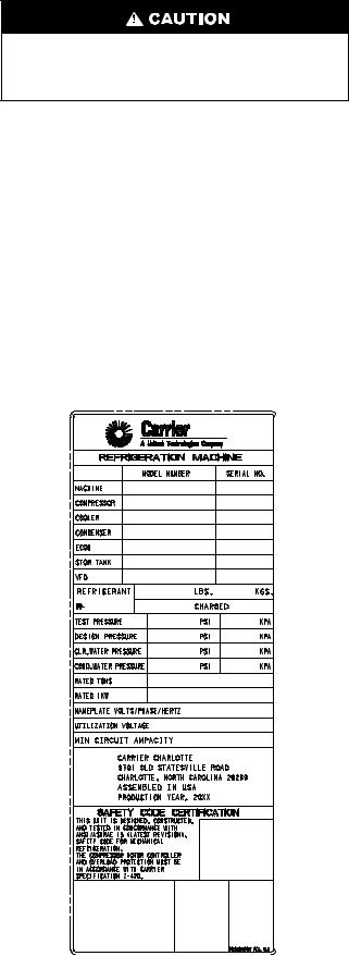
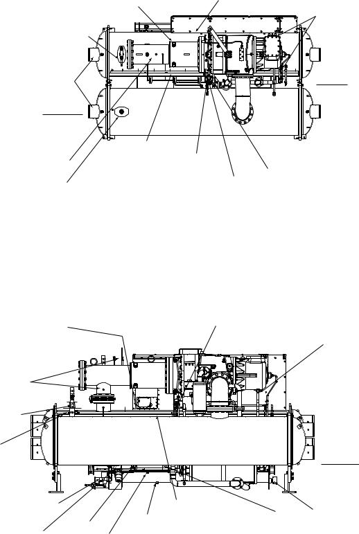
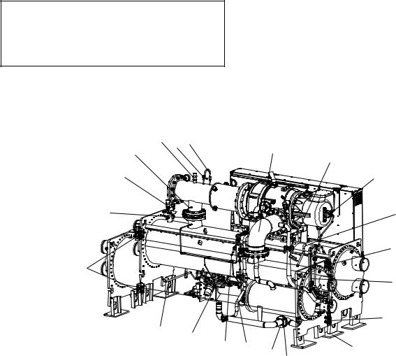
IDENTIFY MACHINE (Fig. 1-4) — Refer to machine nameplate in Fig. 1. The machine model number, serial number, and heat exchanger sizes are stamped on the Refrigeration Machine nameplate located on the side of the VFD (variable frequency drive) enclosure. Check this information against shipping papers and job data.
a23-1547
Fig. 1 — Refrigeration Machine Nameplate
2
|
S –Special |
|
||
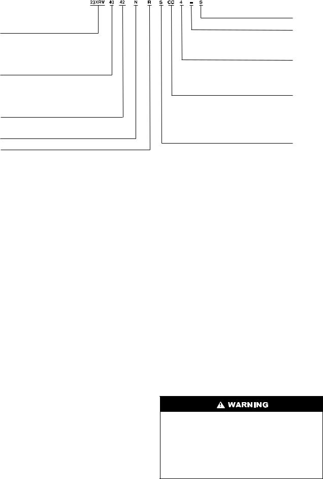
23XRV – High Efficiency |
Not Used |
|
||
Variable Speed Screw Chiller |
|
|||
|
|
|
||
Cooler Size* |
Voltage Code |
|
||
3 – 380-3-60 |
|
|||
30-32 |
|
|||
4 – 416-3-60 |
|
|||
35-37 |
|
|||
5 – 460-3-60 |
|
|||
40-42 |
|
|||
9 – 400-3-50 |
|
|||
45-47 |
|
|
|
|
50-52 |
Drive |
Rectifier Max |
Inverter Max |
|
55-57 |
||||
Frame |
Input Amps† |
Output Amps† |
||
|
||||
Condenser Size* |
AA |
440 |
442 |
|
BA |
520 |
442 |
||
30-32 |
BB |
520 |
520 |
|
35-37 |
CC |
608 |
608 |
|
40-42 |
|
|
|
|
45-47 |
Motor Code |
Max Motor Amps |
||
50-52 |
||||
55-57 |
P |
265 |
|
|
Q |
283 |
|
||
|
|
|||
Economizer Option |
R |
306 |
|
|
S |
334 |
|
||
E – With Economizer |
T |
368 |
|
|
N – No Economizer |
U |
421 |
a23-1533 |
|
|
V |
440 |
|
|
R – Compressor
*First number denotes frame size.
†Maximum limits only. Additional application limits apply that may reduce these ampacities.
Fig. 2 — Model Number Identification
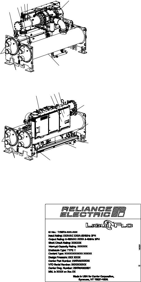
Identifying the Drive by Part Number — Each LiquiFlo™ 2.0 AC drive can be identified by its part number. See Fig. 5. This number appears on the shipping label and on the VFD nameplate.
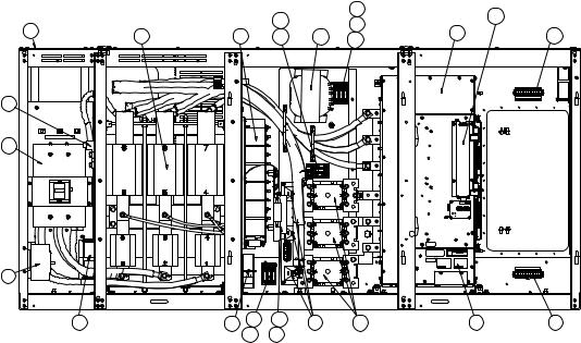
Drive Input Component Location — Figure 6 identifies the control center components.
Identifying the Power Module by I.D. Number — Each LiquiFlo 2.0 AC power module can be identified by its I.D. number. See Fig. 5. This number appears on the shipping label and on the power module’s nameplate. Power ratings are provided in Table 1.
INSTALLATION REQUIREMENTS — Certain requirements should be checked before continuing with the chiller’s electrical installation. Input power wire sizes, branch circuit protection, and control wiring are all areas that need to be evaluated.
Determining Wire Size Requirements — Wire size should be determined based on the size of the conduit openings, and applicable local, national, and international codes (e.g., NEC [National Electric Code]/CEC [California Energy Commission] regulations). General recommendations are included in the Carrier field wiring drawing.
Conduit Entry Size — It is important to determine the size of the conduit openings in the enclosure power entry plate so that the wire planned for a specific entry point will fit through the opening. Do NOT punch holes or drill into the top surface of the control center enclosure for field wiring. Do not punch holes or drill into the top surface of the control center enclosure for field wiring. Knockouts are provided in the back of the control center for field control wiring connections.
Recommended Control and Signal Wire Sizes — The recommended minimum size wire to connect I/O signals to the control terminal blocks is 18 AWG (American Wire Gage). Recommended terminal tightening torque is 7 to 9 in.-lb (0.79 to 1.02 N-m).
Recommended Air Flow Clearances — Be sure there is adequate clearance for air circulation around the enclosure. A 6-in. (152.4 mm) minimum clearance is required wherever vents are located in the VFD enclosure.
Match Power Module Input and Supply Power Ratings — It is important to verify that building power will meet the input power requirements of the Machine Electrical Data nameplate
input power rating. Be sure the input power to the chiller corresponds to the chiller’s nameplate voltage, current, and frequency. Refer to machine nameplate in Fig. 7. The machine electrical data nameplate is located on the right side of the control center.
PROVIDE MACHINE PROTECTION — Protect machine and VFD enclosure from construction dirt and moisture. Keep protective shipping covers in place until machine is ready for installation.
If machine is exposed to freezing temperatures after water circuits have been installed, open waterbox drains and remove all water from cooler and condenser. Leave drains open until system is filled.
It is important to properly plan before installing a 23XRV unit to ensure that the environment and operating conditions are satisfactory. The installation must comply with all requirements in the certified prints.
Rigging the Machine — The 23XRV machine can be rigged as an entire assembly. Large interconnecting piping has flanged connections that allow the compressor, cooler, and condenser sections to be separated and rigged individually. In addition, the VFD can be removed and rigged separately.
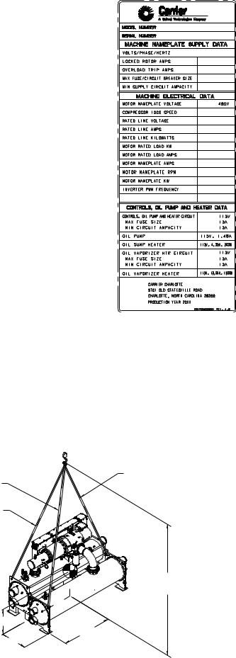
RIG MACHINE ASSEMBLY — See rigging instructions on label attached to machine. Also refer to rigging guide (Fig. 8), physical data in Fig. 9, and Tables 2-9B. Lift machine only from the points indicated in rigging guide. Each lifting cable or chain must be capable of supporting the entire weight of the machine.
Lifting machine from points other than those specified may result in serious damage to the unit and personal injury. Rigging equipment and procedures must be adequate for machine weight. See Fig. 8 for machine weights.
NOTE: These weights are broken down into component sections for use when installing the unit in sections. For the complete machine weight, add all component sections and refrigerant charge together. See Tables 5-9B for machine component weights.
3
1
21
20
19
-1548
41 40 39 38
37
-1549
4
2 3
5
6
7
8
9
10
12 11
13
14
16 15
18 17
22
23
24
25
26
36 35 34
27
33 |
28 |
32 31 30 29
45
42 43 44
46
47
48
49
50
a23-1550 51
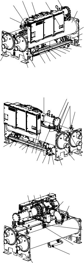
1— Motor Terminal Cover Plate
2— Variable Frequency Drive
3— International Chiller Visual Controller (ICVC)
4— Discharge Pipe Relief Valve
5— Condenser
6— Oil Reclaim Actuator
7— Vaporizer Sight Glass
8— Oil Filter Assembly (Hidden)
9— Vaporizer
10— Oil Charging/Drain Valve
11— Oil Sump
12— Condenser Refrigerant Pumpout Valve
13— Condenser Float Chamber
14— Cooler Inlet Isolation Valve
15— ASME Nameplate, Economizer (Hidden)
16— Filter Drier
17— Oil Sump Heater
18— Condenser Supply/Return End Waterbox
19— Cooler Supply/Return End Waterbox
20— Motor Cooling Supply Line
21— VFD Disconnect
22— Discharge Pipe
23— Compressor Discharge Check Valve Access Cover
24— Condenser Relief Valves
25— Refrigerant Charging Valve
26— Cooler Relief Valve
27— Tubesheet Mounting Brackets
28— Typical Waterbox Drain Coupling
29— ASME Nameplate, Condenser
30— Oil Pump
31— Oil Pump Inlet Strainer
32— Strainer Housing Sight Glass
33— Discharge Isolation Valve (Option or Accessory)
34— Refrigeration Machine Nameplate
35— Machine Electrical Data Nameplate
36— Oil Sump Sight Glass
37— Filter Drier Isolation Valve with Schrader
38— Economizer
39— Motor Cooling Sight Glass
40— Motor Cooling Isolation Valve
41— Vaporizer Drain Sight Glass
42— VFD Cold Plate Refrigeration Inlet Connection (Outlet Hidden)
43— VFD Cold Plate Solenoid
44— Compressor Nameplate
45— Compressor Lubrication Block
46— Economizer Muffler
47— Vaporizer Condenser Gas Isolation Valve
48— Hot Gas Bypass Isolation and Trim Valve
49— VFD Cooling Refrigerant Strainer
50— Cooler Refrigerant Pumpout Valve
51— ASME Nameplate, Cooler
Fig. 3 — Typical 23XRV Components
4
6
4 5
2 3
1
9
7
a23-1551 8
10 |
12 13 |
11 |
14
|
15 |
20 |
16 |
|
|
|
17 |
a23-1552 |
19 |
|
18 |
1— Condenser Pressure
2— Evaporator Pressure
3— Compressor Discharge Temperature
4— Compressor Discharge Pressure
5— Compressor Discharge High Pressure Switch
6— Compressor Motor Winding Temperature (Hidden)
7— Evaporator Refrigerant Liquid Temperature (Hidden)
8— Condenser Liquid Temperature
9— Condenser Liquid Flow (Optional)
10 — Inductor Temperature Switch
(Inside VFD Enclosure)
11 — VFD Rectifier Temperature
(Inside Power Module)
12 — VFD Cold Plate Temperature
(Inside VFD Enclosure)
13 — VFD Inverter Temperature
(Inside Power Module)
14 — Humidity Sensor (Inside VFD Enclosure)
15 — Oil Pressure Leaving Filter (Hidden)
16 — Oil Sump Pressure (Hidden)
17 — Oil Sump Temperature (Hidden)
18 — Vaporizer Temperature
19 — Evaporator Liquid Temperature
20 — Evaporator Liquid Flow (Optional)
Fig. 4 — Typical 23XRV Installation (Sensor Locations)
a23-1553
Fig. 5 — VFD Nameplate
5
6
-a23 |
|
|
1554 |
21 |
1 |
|
|
19
18
17
16
1— Input Inductor Assembly
2— Capacitor Bank Assembly
3— Pre-Charge Resistor Assembly
4— AC Contactor (3)
5— Power Module Assembly
6— Terminal Block, 10-Position (2)
7— Power Module Nameplate
8— Fuse Black, 30A, 600V, Class CC
9— Fuse, Class CC, 600V, 15A (2)
10— Fuse, Class CC, 600V, 5A (1)
11— Fuse, Class CC, 600V, 20A (3)
10
|
11 |
|
9 |
|
20 |
|
|
|
|
|
|
2 |
8 |
13 |
8 |
5 |
6 |
|
16 |
8 |
14 |
3 |
4 |
7 |
6 |
|
|
|||||
|
12 |
15 |
|
|
|
|
12— Fuse, Class CC, 600V, 1A (3)
13— Transformer, 3kVA
14— Line Sync PC Board Assembly
15— Line Sync Board Cover
16— Fan, 115V (3)
17— Circuit Breaker, 600V, 15A
18— Circuit Breaker, 600V
19— Lug, Ground, 2-600 MCM
20— Communications Interface Board
21— Input Power Wiring Panel
Fig. 6 — Control Center Components
a23-1555
Fig. 7 — Machine Electrical Data Nameplate
HEAT EXHANGER |
COMPRESSOR |
MAXIMUM WEIGHT |
VESSEL |
DIM. |
CHAIN LENGTH |
DIM. |
DIM. |
|||
CODE |
FRAME SIZE* |
(lb) |
LENGTH |
“A” |
“B” |
“C” |
“D” |
“E” |
“F” |
|
30-32 |
|
19,187 |
12′ |
6′-10″ |
13′- 5″ |
13′-0″ |
12′- 5″ |
3′-11″ |
3′- 8″ |
|
35-37 |
|
20,589 |
14′ |
7′- 8″ |
13′-10″ |
13′-5″ |
12′-10″ |
3′-11″ |
3′- 8″ |
|
40-42 |
R |
23,928 |
12′ |
6′-10″ |
13′- 6″ |
12′-8″ |
12′- 3″ |
4′- 1″ |
3′-11″ |
|
45-47 |
25,167 |
14′ |
7′- 8″ |
13′-11″ |
13′-2″ |
12′- 8″ |
4′- 1″ |
3′-11″ |
||
|
||||||||||
50-52 |
|
26,950 |
12′ |
6′-10″ |
13′-10″ |
12′-7″ |
12′- 9″ |
4′- 0″ |
4′- 4″ |
|
55-57 |
|
28,479 |
14′ |
7′- 8″ |
14′- 4″ |
13′-1″ |
13′- 1″ |
4′- 0″ |
4′- 4″ |
|
*The 11th character of the chiller model number indicates the frame size of the compressor.
CHAIN “D” CHAIN “B” (SEE NOTE #2) (SEE NOTE #2)
CHAIN “C” (SEE NOTE #2)
15´-0´´ MIN. HEIGHT ABOVE FLOOR
“E”
“A”
“F”
a23-1556
MACHINE RIGGING GUIDE
NOTES:
1.Each chain must be capable of supporting the entire weight of the machine. See chart for maximum weights.
2.Chain lengths shown are typical for 15′ lifting height. Some minor adjustments may be required.
Fig. 8 — Machine Rigging Guide (Cooler Size 30 Through 57)
7
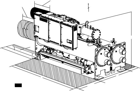
TUBE REMOVAL SPACE FOR EITHER END SIZES 30-32, 40-42, 50-52
12’-7½” (3848 mm) SIZES 35-37, 45-47, 55-57
14’-4” (4369 mm)
0’-3”
0’-3”
4’-10” 0’-5”
MOTOR SERVICE |
|
CLEARANCE |
|
1’ - 10” (559 mm) |
FRAME R COMPRESSOR 3’ - 0” (915mm) |
|
|
|
RECOMMENDED OVERHEAD SERVICE CLEARANCE |
C
2’ MIN
(610 mm)
B
|
A |
(WIDEST POINT) |
|
|
|
SERVICE AREA |
|
4’ - 10” MIN |
a23-1557 |
|
(1219 mm) |
|
|
Fig. 9 — 23XRV Dimensions (Refer to Tables 2 and 3)
Table 1 — Drive Assembly and Power Module Ratings
|
|
ENCLOSURE |
INPUT |
MAX INPUT |
MAX OUTPUT |
|
CARRIER PART NUMBER |
FRAME SIZE |
VOLTAGE (V) |
CURRENT |
CURRENT* at 4kHZ |
||
TYPE |
||||||
|
|
RANGE |
(AMPS) |
(AMPS) |
||
|
|
|
||||
23XRA2AA_ _ _ _ _ _ _ _ _ _ _ |
Frame 2AA |
NEMA 1 |
380 to 460 |
440 |
442 |
|
23XRA2BA_ _ _ _ _ _ _ _ _ _ _ |
Frame 2BA |
NEMA 1 |
380 to 460 |
520 |
442 |
|
23XRA2BB_ _ _ _ _ _ _ _ _ _ _ |
Frame 2BB |
NEMA 1 |
380 to 460 |
520 |
520 |
|
23XRA2CC_ _ _ _ _ _ _ _ _ _ _ |
Frame 2CC |
NEMA 1 |
380 to 460 |
608 |
608 |
*110% output current capability for one minute, 150% output current for 5 seconds.
Table 2 — 23XRV Dimensions (Nozzle-In-Head Waterbox)
HEAT EXCHANGER |
|
A (Length, with Nozzle-in-Head Waterbox) |
|
|
B (Width) |
C (Height) |
|||||
1 Pass |
2-Pass* |
3 Pass† |
|
||||||||
SIZE |
|
|
|
|
|
||||||
|
ft-in. |
mm |
ft-in. |
mm |
ft-in. |
mm |
ft-in. |
mm |
ft-in. |
mm |
|
30 to 32 |
14- 31/4 |
4350 |
13- 81/4 |
4172 |
14- 31/4 |
4350 |
6- |
4 |
1930 |
7-25/8 |
2200 |
35 to 37 |
15-113/4 |
4870 |
15- 43/4 |
4693 |
15-113/4 |
4870 |
6- |
4 |
1930 |
7-25/8 |
2200 |
40 to 42 |
14- 9 |
4496 |
14- 31/8 |
4347 |
14- 6 |
4420 |
6- 8½ |
2045 |
7-6½ |
2299 |
|
45 to 47 |
16- 51/2 |
5017 |
15-115/8 |
4867 |
16- 21/2 |
4940 |
6- 8½ |
2045 |
7-6½ |
2299 |
|
50 to 52 |
14-10 |
4521 |
14- 41/2 |
4382 |
14- 61/2 |
4432 |
6-113/4 |
2127 |
7-63/4 |
2305 |
|
55 to 57 |
16- 61/2 |
5042 |
16- 1 |
4902 |
16- 3 |
4953 |
6-113/4 |
2127 |
7-63/4 |
2305 |
|
*Assumes both cooler and condenser nozzles on same end of chiller.
†1 or 3 pass length applies if either (or both) cooler or condenser is a 1 or 3 pass design. NOTES:
1.Service access should be provided per American Society of Heating, Refrigeration, and Air Conditioning Engineers (ASHRAE) 15, latest edition, National Fire Protection Association (NFPA) 70, and local safety code.
2.Allow at least 3 ft (915 mm) overhead clearance for service rigging for frame R compressor.
3.Certified drawings available upon request.
4.Marine waterboxes may add 6 in. to the width of the machine. See certified drawings for details.
5.‘A’ length dimensions shown are for standard 150 psi design and victaulic connections. The 300 psi design and/or flanges will add length. See certified drawings.
6.Dished head waterbox covers not available for 3 pass design.
8
Table 3 — 23XRV Dimensions (Marine Waterbox)
HEAT EXCHANGER |
A (Length, Marine Waterbox — not shown) |
MAXIMUM |
MAXIMUM |
|||||||
2-Pass* |
|
1 or 3 Pass† |
|
B WIDTH |
C HEIGHT |
|||||
SIZE |
|
|
||||||||
|
ft-in. |
|
mm |
ft-in. |
mm |
ft-in. |
|
mm |
ft-in. |
mm |
30 to 32 |
14- 9 |
|
4496 |
16-43/4 |
4997 |
6-93/8 |
|
2067 |
7-25/8 |
2200 |
35 to 37 |
16- 51/2 |
|
5017 |
18-11/4 |
5518 |
6-93/8 |
|
2067 |
7-25/8 |
2200 |
40 to 42 |
15- 23/4 |
|
4642 |
16-81/4 |
5086 |
6-93/4 |
|
2076 |
7-61/2 |
2299 |
45 to 47 |
16-111/4 |
|
5163 |
18-43/4 |
5607 |
6-93/4 |
|
2076 |
7-61/2 |
2299 |
50 to 52 |
15- 31/2 |
|
4661 |
16-81/2 |
5093 |
7-1 |
|
2159 |
7-63/4 |
2305 |
55 to 57 |
17- 0 |
|
5182 |
18-5 |
5613 |
7-1 |
|
2159 |
7-63/4 |
2305 |
*Assumes both cooler and condenser nozzles on same end of chiller. †1 or 3 pass length applies if cooler is a 1 or 3 pass design.
NOTES:
1.Service access should be provided per American Society of Heating, Refrigeration, and Air Conditioning Engineers (ASHRAE) 15, latest edition, National Fire Protection Association (NFPA) 70, and local safety code.
2.Allow at least 3 ft (915 mm) overhead clearance for service rigging for frame R compressor.
3.Certified drawings available upon request.
4.Marine waterboxes may add 6 in. to the width of the machine. See certified drawings for details.
5.‘A’ length and ‘B’ width dimensions shown are for standard 150 psi design and victaulic connections. The 300 psi design and/ or flanges will add length. See certified drawings.
Table 4 — 23XRV Waterbox Nozzle Sizes
FRAME |
PRESSURE |
PASS |
NOMINAL PIPE SIZE (in.) |
ACTUAL PIPE ID (in.) |
|||
SIZE |
psig (kPa) |
Cooler |
Condenser |
Cooler |
Condenser |
||
|
|||||||
|
150/300 |
1 |
10 |
10 |
10.020 |
10.020 |
|
3 |
2 |
8 |
8 |
7.981 |
7.981 |
||
(1034/2068) |
|||||||
|
3 |
6 |
6 |
6.065 |
6.065 |
||
|
|
||||||
|
150/300 |
1 |
10 |
10 |
10.020 |
10.020 |
|
4 |
2 |
8 |
8 |
7.981 |
7.981 |
||
(1034/2068) |
|||||||
|
3 |
6 |
6 |
6.065 |
6.065 |
||
|
|
||||||
|
150/300 |
1 |
10 |
10 |
10.020 |
10.020 |
|
5 |
2 |
8 |
10 |
7.981 |
10.020 |
||
(1034/2068) |
|||||||
|
3 |
6 |
8 |
6.065 |
7.981 |
||
|
|
||||||
Table 5 — 23XRV Compressor Weights
|
ENGLISH |
SI |
MOTOR |
Total Compressor |
Total Compressor |
CODE |
Weight* |
Weight* |
|
(lb) |
(kg) |
P |
|
|
Q |
|
|
R |
|
|
S |
4866 |
2207 |
T |
|
|
U |
|
|
V |
|
|
*Compressor weight is comprised of compressor, stator, rotor, and end bell.
Table 6 — 23XRV Component Weights — TR Compressor
|
FRAME 3 |
|
FRAME 4 |
|
FRAME 5 |
|
|||
COMPONENT |
HEAT EXCHANGER* |
HEAT EXCHANGER* |
HEAT EXCHANGER* |
||||||
|
lb |
|
kg |
lb |
|
kg |
lb |
|
kg |
Suction Elbow |
179 |
|
81 |
237 |
|
108 |
232 |
|
105 |
Discharge Pipe Assembly |
747 |
|
339 |
747 |
|
339 |
747 |
|
339 |
Control Center |
1650 |
|
749 |
1650 |
|
749 |
1650 |
|
749 |
Discharge Pipe Adapter Flange |
178 |
|
81 |
178 |
|
81 |
178 |
|
81 |
Optional Isolation Valves |
70 |
|
32 |
70 |
|
32 |
115 |
|
52 |
Optional Unit Mounted Pumpout Unit |
164 |
|
75 |
164 |
|
75 |
164 |
|
75 |
Vaporizer Oil Sump |
700 |
|
318 |
700 |
|
318 |
700 |
|
318 |
Economizer |
542 |
|
246 |
542 |
|
246 |
542 |
|
246 |
*To determine compressor frame size, refer to Fig. 2.
9
Table 7 — 23XRV Heat Exchanger Data
|
|
|
ENGLISH |
|
|
|
|
SI |
|
|
|
|
||
|
Dry Rigging Weight |
|
Machine Charge |
|
Dry Rigging Weight |
|
|
Machine Charge |
|
|
||||
|
|
(lb)* |
|
|
|
(kg)* |
|
|
|
|
||||
|
|
|
|
|
|
|
|
|
|
|
|
|
||
CODE |
|
|
Refrigerant |
Liquid Weight |
|
|
Refrigerant |
|
Liquid |
|||||
|
Cooler |
Condenser |
Weight (lb) |
|
(lb) |
Cooler |
Condenser |
Weight (kg) |
Weight (kg) |
|||||
|
Only |
Only |
With |
Without |
Cooler |
Condenser |
Only |
Only |
With |
|
Without |
Cooler |
|
Condenser |
|
|
|
Economizer |
Economizer |
|
|
Economizer |
|
Economizer |
|
||||
30 |
4148 |
3617 |
800 |
650 |
464 |
464 |
1877 |
1676 |
363 |
|
295 |
210 |
|
210 |
31 |
4330 |
3818 |
800 |
650 |
531 |
542 |
1959 |
1769 |
363 |
|
295 |
241 |
|
246 |
32 |
4522 |
4023 |
800 |
650 |
601 |
621 |
2046 |
1860 |
363 |
|
295 |
273 |
|
282 |
35 |
4419 |
4529 |
910 |
760 |
511 |
513 |
2000 |
2089 |
413 |
|
345 |
232 |
|
233 |
36 |
4627 |
4758 |
910 |
760 |
587 |
602 |
2094 |
2195 |
413 |
|
345 |
266 |
|
273 |
37 |
4845 |
4992 |
910 |
760 |
667 |
692 |
2193 |
2299 |
413 |
|
345 |
303 |
|
314 |
40 |
5008 |
4962 |
900 |
750 |
863 |
915 |
2675 |
2746 |
408 |
|
340 |
391 |
|
415 |
41 |
5178 |
5155 |
900 |
750 |
930 |
995 |
2758 |
2839 |
408 |
|
340 |
422 |
|
451 |
42 |
5326 |
5347 |
900 |
750 |
990 |
1074 |
2832 |
2932 |
408 |
|
340 |
449 |
|
487 |
45 |
5463 |
5525 |
1015 |
865 |
938 |
998 |
2882 |
3001 |
460 |
|
392 |
425 |
|
453 |
46 |
5659 |
5747 |
1015 |
865 |
1014 |
1088 |
2976 |
3108 |
460 |
|
392 |
460 |
|
494 |
47 |
5830 |
5967 |
1015 |
865 |
1083 |
1179 |
3061 |
3214 |
460 |
|
392 |
491 |
|
535 |
50 |
5827 |
6013 |
1250 |
1100 |
1101 |
1225 |
3182 |
3304 |
567 |
|
499 |
499 |
|
556 |
51 |
6053 |
6206 |
1250 |
1100 |
1192 |
1304 |
3294 |
3397 |
567 |
|
499 |
541 |
|
591 |
52 |
6196 |
6387 |
1250 |
1100 |
1248 |
1379 |
3364 |
3485 |
567 |
|
499 |
566 |
|
626 |
55 |
6370 |
6708 |
1430 |
1280 |
1201 |
1339 |
3429 |
3620 |
649 |
|
581 |
545 |
|
607 |
56 |
6631 |
6930 |
1430 |
1280 |
1304 |
1429 |
3556 |
3726 |
649 |
|
581 |
591 |
|
648 |
57 |
6795 |
7138 |
1430 |
1280 |
1369 |
1514 |
3636 |
3826 |
649 |
|
581 |
621 |
|
687 |
*Rigging weights are for standard tubes of standard wall thickness (Turbo-B3 and Spikefin 2, 0.025-in. [0.635 mm] wall).
NOTES:
1.Cooler includes the suction elbow and 1/2 the distribution piping weight.
2.Condenser includes float valve and sump, discharge stub-out, and 1/2 the distribution piping weight.
3.For special tubes refer to the 23XRV Computer Selection Program.
4.All weights for standard 2-pass NIH (nozzle-in-head) design with victaulic grooves.
Table 8A — 23XRV Additional Data for Cooler Marine Waterboxes*
HEAT EXCHANGER |
|
ENGLISH |
|
|
SI |
|
FRAME, PASS |
Psig |
Rigging Weight |
Water Volume |
kPa |
Rigging Weight |
Water Volume |
|
|
(lb) (see Note 2) |
(gal) |
|
(kg) (see Note 2) |
(L) |
FRAME 3, 1 AND 3 PASS |
150 |
730 |
84 |
1034 |
331 |
318 |
FRAME 3, 2 PASS |
150 |
365 |
42 |
1034 |
166 |
159 |
FRAME 4, 1 AND 3 PASS |
150 |
1888 |
109 |
1034 |
856 |
413 |
FRAME 4, 2 PASS |
150 |
944 |
54 |
1034 |
428 |
204 |
FRAME 5, 1 AND 3 PASS |
150 |
2445 |
122 |
1034 |
1109 |
462 |
FRAME 5, 2 PASS |
150 |
1223 |
61 |
1034 |
555 |
231 |
FRAME 3, 1 AND 3 PASS |
300 |
860 |
84 |
2068 |
390 |
318 |
FRAME 3, 2 PASS |
300 |
430 |
42 |
2068 |
195 |
159 |
FRAME 4, 1 AND 3 PASS |
300 |
2162 |
109 |
2068 |
981 |
413 |
FRAME 4, 2 PASS |
300 |
1552 |
47 |
2068 |
704 |
178 |
FRAME 5, 1 AND 3 PASS |
300 |
2655 |
122 |
2068 |
1204 |
462 |
FRAME 5, 2 PASS |
300 |
1965 |
53 |
2068 |
891 |
201 |
*Add to heat exchanger data for total weights or volumes.
NOTES:
1.Weight adder shown is the same for cooler and condenser of equal frame size.
2.For the total weight of a vessel with a marine waterbox, add these values to the heat exchanger weights (or volume).
10
Table 8B — 23XRV Additional Data for Condenser Marine Waterboxes*
HEAT EXCHANGER |
|
ENGLISH |
|
|
SI |
|
FRAME, PASS |
Psig |
Rigging Weight |
Water Volume |
kPa |
Rigging Weight |
Water Volume |
|
|
(lb) (see Note 2) |
(gal) |
|
(kg) (see Note 2) |
(L) |
FRAME 3, 1 AND 3 PASS |
150 |
N/A |
N/A |
1034 |
N/A |
N/A |
FRAME 3, 2 PASS |
150 |
365 |
42 |
1034 |
166 |
159 |
FRAME 4, 1 AND 3 PASS |
150 |
N/A |
N/A |
1034 |
N/A |
N/A |
FRAME 4, 2 PASS |
150 |
989 |
54 |
1034 |
449 |
204 |
FRAME 5, 1 AND 3 PASS |
150 |
N/A |
N/A |
1034 |
N/A |
N/A |
FRAME 5, 2 PASS |
150 |
1195 |
60 |
1034 |
542 |
227 |
FRAME 3, 1 AND 3 PASS |
300 |
N/A |
N/A |
2068 |
N/A |
N/A |
FRAME 3, 2 PASS |
300 |
430 |
42 |
2068 |
195 |
159 |
FRAME 4, 1 AND 3 PASS |
300 |
N/A |
N/A |
2068 |
N/A |
N/A |
FRAME 4, 2 PASS |
300 |
1641 |
47 |
2068 |
744 |
178 |
FRAME 5, 1 AND 3 PASS |
300 |
N/A |
N/A |
2068 |
N/A |
N/A |
FRAME 5, 2 PASS |
300 |
1909 |
50 |
2068 |
866 |
189 |
*Add to heat exchanger data for total weights or volumes.
NOTES:
1.Weight adder shown is the same for cooler and condenser of equal frame size.
2.For the total weight of a vessel with a marine waterbox, add these values to the heat exchanger weights (or volume).
Table 9A — 23XRV Waterbox Cover Weights — English (lb)
|
|
|
COOLER |
|
|
|
|
CONDENSER |
|
|
||
WATERBOX |
Frame 3 |
Frame 4 |
Frame 5 |
Frame 3 |
Frame 4 |
Frame 5 |
||||||
DESCRIPTION |
Victaulic |
Flanged |
Victaulic |
Flanged |
Victaulic |
Flanged |
Victaulic |
Flanged |
Victaulic |
Flanged |
Victaulic |
Flanged |
|
||||||||||||
|
Nozzles |
|
Nozzles |
|
Nozzles |
|
Nozzles |
|
Nozzles |
|
Nozzles |
|
NIH,1 pass Cover 150 PSIG |
282 |
318 |
148 |
185 |
168 |
229 |
282 |
318 |
148 |
185 |
168 |
229 |
NIH,2 pass Cover 150 PSIG |
287 |
340 |
202 |
256 |
222 |
276 |
287 |
340 |
191 |
245 |
224 |
298 |
NIH,3 pass Cover 150 PSIG |
294 |
310 |
472 |
488 |
617 |
634 |
294 |
310 |
503 |
519 |
628 |
655 |
NIH Plain End, 150 PSIG |
243 |
243 |
138 |
138 |
154 |
154 |
225 |
225 |
138 |
138 |
154 |
154 |
MWB End Cover, 150 PSIG* |
243/315 |
243/315 |
138/314 |
138/314 |
154/390 |
154/390 |
225/234 |
225/234 |
138/314 |
138/314 |
154/390 |
154/390 |
NIH,1 pass Cover 300 PSIG |
411 |
486 |
633 |
709 |
764 |
840 |
411 |
486 |
633 |
709 |
764 |
840 |
NIH,2 pass Cover 300 PSIG |
411 |
518 |
626 |
733 |
760 |
867 |
411 |
578 |
622 |
729 |
727 |
878 |
NIH,3 pass Cover 300 PSIG |
433 |
468 |
660 |
694 |
795 |
830 |
433 |
468 |
655 |
689 |
785 |
838 |
NIH Plain End, 300 PSIG |
291 |
291 |
522 |
522 |
658 |
658 |
270 |
270 |
522 |
522 |
658 |
658 |
MWB End Cover, 300 PSIG* |
445/619 |
445/619 |
522/522 |
522/522 |
658/658 |
658/658 |
359/474 |
359/474 |
522/522 |
522/522 |
658/658 |
658/658 |
*Rows with two entries list nozzle end and return end weights.
Table 9B — 23XRV Waterbox Cover Weights — SI (kg)
|
|
|
COOLER |
|
|
|
|
CONDENSER |
|
|
|||
WATERBOX |
Frame 3 |
Frame 4 |
Frame 5 |
Frame 3 |
Frame 4 |
Frame 5 |
|||||||
DESCRIPTION |
|
|
|
|
|
|
|
|
|
|
|
|
|
Victaulic |
Flanged |
Victaulic |
Flanged |
Victaulic |
Flanged |
Victaulic |
Flanged |
Victaulic |
Flanged |
Victaulic |
Flanged |
||
|
|||||||||||||
|
Nozzles |
|
Nozzles |
|
Nozzles |
|
Nozzles |
|
Nozzles |
|
Nozzles |
|
|
NIH,1 pass Cover 150 PSIG |
128 |
144 |
67 |
84 |
76 |
104 |
128 |
144 |
67 |
84 |
76 |
104 |
|
NIH,2 pass Cover 150 PSIG |
130 |
154 |
92 |
116 |
101 |
125 |
130 |
154 |
87 |
111 |
102 |
135 |
|
NIH,3 pass Cover 150 PSIG |
133 |
141 |
214 |
221 |
280 |
288 |
133 |
141 |
228 |
235 |
285 |
297 |
|
NIH Plain End, 150 PSIG |
110 |
110 |
63 |
63 |
70 |
70 |
102 |
102 |
63 |
63 |
70 |
70 |
|
MWB End Cover, 150 PSIG |
110/143 |
110/143 |
63/142 |
63/142 |
70/177 |
70/177 |
102/106 |
102/106 |
63/142 |
63/142 |
70/177 |
70/177 |
|
NIH,1 pass Cover 300 PSIG |
186 |
220 |
287 |
322 |
347 |
381 |
186 |
220 |
287 |
322 |
346 |
381 |
|
NIH,2 pass Cover 300 PSIG |
186 |
235 |
284 |
332 |
344 |
393 |
186 |
235 |
282 |
331 |
330 |
398 |
|
NIH,3 pass Cover 300 PSIG |
196 |
212 |
299 |
315 |
361 |
376 |
196 |
212 |
297 |
313 |
356 |
380 |
|
NIH Plain End, 300 PSIG |
132 |
132 |
237 |
237 |
298 |
298 |
122 |
122 |
237 |
237 |
298 |
298 |
|
MWB End Cover, 300 PSIG |
202/281 |
202/281 |
237/237 |
237/237 |
298/298 |
298/298 |
163/215 |
163/215 |
237/237 |
237/237 |
298/298 |
298/298 |
|
LEGEND
NIH — Nozzle-in-Head
MWB — Marine Waterbox
*Rows with two entries list nozzle end and return end weights.
NOTE: Weight for NIH 2-pass cover, 150 psig (1034 kPa), is included in the heat exchanger weights shown in Table 7.
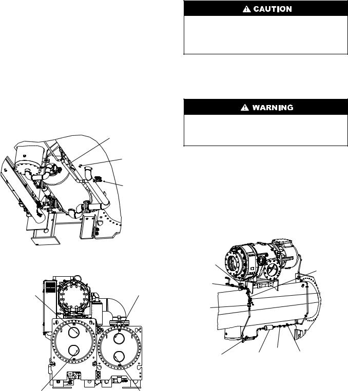
RIG MACHINE COMPONENTS — Refer to Fig. 10-26 and Carrier Certified Prints for machine component disassembly.
IMPORTANT: Only a qualified service technician should perform this operation.
Do not attempt to disconnect flanges while the machine is under pressure. Failure to relieve pressure can result in personal injury or damage to the unit.
Before rigging the compressor remove control panel and control center.
NOTE: Label each wire before removal when wiring must be disconnected (see Fig. 10 and 11). Clip all wire ties necessary when removing pressure and temperature sensors. Disconnect all pressure transducer wires at the sensor. Temperature sensors cannot be disconnected from their cables; remove temperature sensors from their thermowells and label as required.
11
|
CABLE TRAY CONTAINING |
|
|
VAPORIZER HTR CONDUIT |
|
|
OIL HEATER CONDUIT |
|
|
OIL PUMP CONDUIT |
|
|
OIL SUMP TEMP. CABLE |
|
|
OIL SUMP PRESS. CABLE |
|
|
OIL PRESS. CABLE |
|
OIL RECLAIM ACTUATOR CABLE |
||
|
HGBP CONDUIT (OPTIONAL) |
|
CONDENSER |
|
|
PRESSURE |
|
|
CABLE |
|
|
WATER SENSOR CABLES |
|
|
FOR NOZZLE ARRANGEMENTS |
|
|
A,B,C,E,F,P,Q,R,T,&U |
|
|
(SAME FOR OTHER END |
|
|
OF MACHINE) |
|
|
DISCHARGE END |
|
|
|
CABLE TRAY CONTAINING |
|
DISCH. TEMP. CABLE |
ENT/LVG CHILLED LIQUID CABLES |
|
ENT/LVG COND. LIQUID CABLES |
||
DISCH. PRESS. CABLE |
||
COND, PRESS CABLE |
||
DISCH. PRESS. SWITCH |
||
COMP’R DISCH TEMP. CABLE |
||
|
||
|
EVAP. PRESS. CABLE |
|
COOLER |
EVAP. REFRIG. LIQUID TEMP. CABLE |
|
MOTOR TEMP. CABLE |
||
PRESSURE |
VFD COOLANT SOLENOID CABLE |
|
CABLE |
OIL PRESS. CABLE |
|
DISCH. PRESS. SWITCH CABLE
HGBP CONDUIT (OPTIONAL)
CONTROL
PANEL
MOTOR TEMPERATURE
CABLE
SUCTION END
VFD COOLING
SOLENOID
CABLE
HGBP CONDUIT (OPTIONAL)
EVAP REFRIG. LIQUID |
LEGEND |
TEMP. CABLE |
|
HGBP |
— Hot Gas Bypass |
HTR |
— Heater |
ENT/LVG — Entering/Leaving
Fig. 10 — Electrical Cable Routing (Top View)
CABLE TRAY CONTAINING
OIL VAPORIZER CONDUIT
OIL HTR CONDUIT
OIL PUMP CONDUIT
OIL RECLAIM ACTUATOR CABLE OIL SUMP PRESS. CABLE OIL DISCH. PRESS. CABLE
OIL SUMP TEMP. CABLE
HGBP CONDUIT (OPTIONAL) COMR’R DISCH. TEMP. CABLE DISCH. PRESS. SWITCH DISCH. PRESS. CABLE
COMP’R DISCHARGE
TEMP. CABLE
DISCH. PRESS. CABLE
DISCH. PRESS. SWITCH
CONDENSER
PRESSURE
CABLE
EVAPORATOR
PRESSURE
CABLE
DISCHARGE END
VFD COOLING
SOLENOID
MOTOR TEMP
CABLE
SUCTION END
|
|
OIL PUMP |
|
|
CABLE TRAY CONTAINING |
OIL HEATER |
|
|
CONDUIT |
|
|
VAPORIZER HEATER CONDUIT |
CONDUIT |
|
LEGEND |
|
OIL |
OIL SUMP |
OIL HTR CONDUIT |
EVAPORATOR |
|
|
OIL PUMP CONDUIT |
REFRIG LIQUID |
|||
|
|
TEMPERATURE |
||||
|
|
|
PRESSURE |
OIL RECLAIM ACTUATOR CABLE |
TEMPERATURE |
|
HGBP |
— Hot Gas Bypass |
|
LEAVING |
CABLE |
OIL SUMP PRESS. CABLE |
SENSOR CABLE |
OIL RECLAIM |
|
|||||
HTR |
— Heater |
FILTER |
OIL SUMP |
OIL PRESS. CABLE |
|
|
ACTUATOR |
|
|||||
ENT/LVG— Entering/Leaving |
CABLE |
PRESSURE |
OIL SUMP TEMP. CABLE |
|
||
CABLE |
|
|||||
|
CABLE |
HGBP CONDUIT (OPTIONAL) |
a23-1559 |
|||
|
|
|
|
|||
|
|
|
|
|
|
|
Fig. 11 — Electrical Cable Routing (Back View)
12
Separate Machine Components — The design of the 23XRV allows for disassembly at the job site so that individual components may be moved through existing doorways. Use the following procedures to separate the machine components.
Suggested locations to cut piping will minimize the width of the condenser/economizer assembly.
SEPARATE COOLER AND CONDENSER
IMPORTANT: If the cooler and condenser vessels must be separated, the heat exchangers should be kept level by placing a support plate under the tube sheets. The support plate will also help to keep the vessels level and aligned when the vessels are bolted back together.
NOTE: For steps 1 through 13 refer to Fig. 12. The cooler has been removed from the picture to show the pipes and lines that must be cut.
Check that the holding charge has been removed from the chiller.
1.Place a support plate under each tube sheet to keep each vessel level.
2.Remove cooler relief valve and relief valve vent piping.
3.Cut the motor cooling refrigerant drain line.
4.Rig the suction elbow and disconnect the compressor suction line at the cooler and compressor. Remove bolts from the vaporizer vent line flange.
5.Cut the VFD cooling drain line.
6.Cut the oil reclaim line(s).
7.Cut the hot gas bypass line between the HGBP (hot gas bypass) solenoid valve and the cooler feed line.
8.Unbolt the cooler liquid feed line near the economizer or condenser float chamber at the flanged connection. Temporarily secure the in-line economizer orifice plate (economized chillers only) to the economizer flange (see Fig. 12).
|
17 |
19 |
|
|
|
|
18 |
|
1 |
|
|
|
16 |
|
|
|
|
|
|
|
|
2 |
|
|
15 |
|
|
|
3 |
|
|
|
|
|
|
|
14 |
|
|
|
4 |
|
|
|
|
|
5 |
|
5 |
|
|
|
|
|
|
|
|
|
6 |
|
|
|
|
|
5 |
|
13 |
12 |
|
|
|
|
|
|
|
|
|
|
|
11 |
|
10 |
7 |
|
|
|
|
9 |
|
|
a23-1560 |
|
|
|
|
|
|
|
8 |
|
|
1 |
— Suction Elbow (Unbolt) |
|
11 |
— VFD Cooling Drain Line |
|
2 |
— Vaporizer Vent Line (Unbolt) |
|
12 |
— Oil Reclaim Line (Cut) |
|
3 |
— Motor Cooling Line (Unbolt) |
|
13 |
— Vaporizer Hot Gas Return Line (Cut) |
|
4 |
— Motor Cooling Drain Line (Cut) |
14 |
— Discharge Isolation Valve (Optional) |
||
5 |
— Tubesheet Mounting Bracket |
|
15 |
— Condenser Relief Valves (Unscrew) |
|
6 |
— Bearing Oil Drain Line |
|
16 |
— Discharge Temperature Sensor |
|
7 |
— Support Plate |
|
17 |
— Discharge Pipe Assembly Relief Valve (Unscrew) |
|
8 |
— In-Line Economizer Orifice Plate |
18 |
— Discharge Pressure Sensor |
|
|
9 |
— Cooler Liquid Feed LIne (Unbolt) |
19 |
— Discharge Pressure Switch |
|
|
10 |
— Hot Gas Bypass Line (Cut) |
|
|
|
|
Fig. 12 — Cooler/Discharge Pipe Assembly Removal
13
9. Cut the vaporizer refrigerant return line as shown.
10. Disconnect all sensors with cables that cross from the condenser side of the machine to the cooler side including:
a.Evaporator refrigerant liquid temperature sensor. See Fig. 13.
b.Entering and leaving chiller liquid temperature sensors. See Fig. 14.
c.Evaporator pressure sensor.
11.Disconnect the tubesheet mounting brackets from the vessel connectors on the tube cooler tubesheet.
12.Cover all openings.
13.Rig the cooler away from the condenser/compressor.
NOTE: To reassemble, follow steps in reverse order. Connect sensors and cables after major components have been secured to reduce the risk damaging them.
OPTIONAL
HOT GAS
BYPASS LINE
EVAPORATOR
REFRIGERANT
LIQUID
TEMPERATURE
SENSOR
COOLER
REFRIGERANT
PUMPOUT
VALVE
a23-1635
Fig. 13 — Evaporator Refrigerant Liquid Temperature Sensor on Bottom of Cooler
LEAVING CONDENSER |
LEAVING CHILLED |
LIQUID TEMPERATURE |
LIQUID TEMPERATURE |
SENSOR |
SENSOR |
ENTERING CONDENSER |
|
ENTERING CHILLED |
|
LIQUID TEMPERATURE |
a23-1563 |
LIQUID TEMPERATURE |
|
SENSOR |
SENSOR |
||
|
Fig. 14 — Chiller End View
Do not rig the condenser before the control center and compressor are removed. The condenser/compressor assembly has a high center of gravity and may tip over when lifted at the tubesheet rigging points, which could result in equipment damage and/or serious personal injury.
REMOVE THE CONTROLS/DRIVE ENCLOSURE FROM THE CONDENSER — Confirm that the power supply disconnect is open and all safety procedures are observed before removing the VFD. This procedure minimizes the number of sensors and cables that need to be disconnected.
Do not attempt to remove the VFD without first isolating the refrigerant charge in the condenser. Damage to one of the motor terminals during VFD removal will result in an uncontrolled refrigerant leak.
1.Close the 2 filter drier isolation valves (Fig. 15) and the 2 VFD isolation valves. Isolate the refrigerant charge into the condenser to prevent a refrigerant leak if one of the motor terminals is accidentally damaged during VFD removal or installation. Evacuate the VFD coldplate through the Schrader valve (Fig. 15) on the VFD drain isolation valve.
2.Remove the shipping bracket between the VFD and the compressor if it is still in place. Remove any conduits that bring power to the VFD. See Fig. 16.
VFD |
|
REFRIGERANT |
|
COOLING |
|
SOLENOID |
SCHRADER |
VALVE |
|
VFD |
VALVE |
|
|
REFRIGERANT |
|
COOLING |
|
ISOLATION |
VFD DRAIN |
VALVE |
ISOLATION |
VFD |
VALVE |
REFRIGERANT |
|
STRAINER |
|
|
|
MOTOR |
FILTER DRIER |
|
FILTER DRIER |
FILTER |
COOLING |
||
SIGHT |
ISOLATION VALVE |
|||
ISOLATION VALVE |
DRIER |
|||
GLASS |
|
|||
|
|
|
a23-1564
Fig. 15 — VFD Refrigerant Isolation Valves
14

SHIPPING
BRACKET
a23-1565
Fig. 16 — VFD Shipping Bracket
3.Remove the nuts that secure the terminal box transition piece to the motor housing.
4.Disconnect the motor leads from the motor terminals (Fig. 17). Note the position of the motor terminal cable lugs so they can be reinstalled with sufficient clearance away from surrounding structure.
5.Remove the motor temperature sensor leads (Fig. 17), the motor ground lead, and the bolts that secure the VFD enclosure to the terminal box transition piece.
6.Disconnect the communication cables from the back of the ICVC (Fig. 18).
7.Disconnect the high pressure switch leads from terminal strip TB1, terminals 15 and 16 (Fig. 19).
8.Unplug connectors CN1A, CN1B, CN2, and CN3 (Fig. 19).
9.Disconnect the control panel ground wire (Fig. 19) that is located next to connectors CN1A and CN1B.
10.Disconnect the VFD cooling lines (Fig. 20) and cover all openings.
11.Remove the 12 screws that secure the control panel to the VFD enclosure. Tilt the control panel away from the back of the control center.
12.Position the control panel on top of the condenser and secure it in place to prevent damage.
MOTOR TERMINALS
MOTOR TERMINAL
BOX FRAME
MOTOR
TEMPERATURE
SENSOR TERMINAL
BLOCK
MOTOR |
|
TEMPERATURE |
a23-1566 |
CABLE |
Fig. 17 — Motor Terminals
a23-1567
Fig. 18 — ICVC Communication Cables
CONNECTOR CN2
a23-1570
|
CONTROL PANEL |
CONNECTOR CN1A |
GROUND WIRE |
CONNECTOR CN1B
HIGH
 PRESSURE
SWITCH
CABLE
LOW VOLTAGE FIELD
WIRING TERMINAL STRIP
CONNECTOR CN3
Fig. 19 — Control Panel Connectors
15
OIL HEATER CONDUIT ASY
OIL PUMP CONDUIT ASY
VAPORIZER HEATER CONDUIT ASY
VFD COOLING LINE
O-RING FACE SEAL
COUPLINGS
OIL RECLAIM
ACTUATOR CABLE
VFD COOLING
SOLENOID CABLE
TEMPERATURE SENSOR CABLES
PRESSURE SENSOR a23-1571 CABLES
Fig. 20 — Control Panel Back
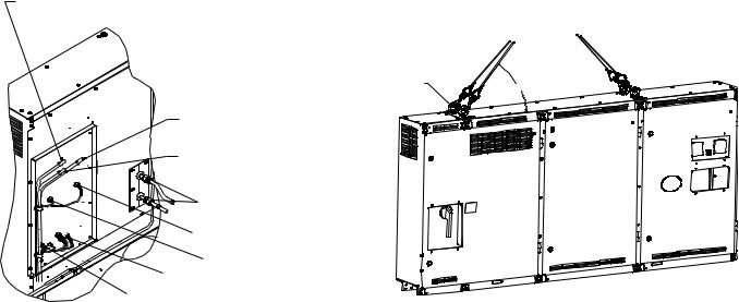
Lifting the Control Center — Care should be used to prevent damage due to dropping or jolting when moving the control center. A fork truck or similar means of lifting and transporting may be used. Sling in a manner that will equalize the load at the pickup points. Use a spreader bar if the angle of the sling is less than 45 degrees relative to horizontal. Do not jolt while lifting.
Use the following procedure to lift the control center.
1.Remove the rubber hole plugs in the top of the control center and fully thread in 4 eyebolts or swivel hoist rings
(see Fig. 21). Lifting hardware must have 3/4 in.-10 x 2 in. long threads and must have a working load limit of at least 6000 lb (2722 kg). Typical eyebolts are Chicago Hardware (size 28) or Grainger (P/N 5ZA63).
2.Attach a sling to the four lifting eyebolts. Make certain that the angle of the sling is not less than 45 degrees relative to horizontal.
3.Using an overhead or portable hoist (minimum 2 ton rated capacity), attach a free-fall chain to the sling secured to the drive. Take up any slack in the chain.
4.Rig the control center and remove the bolts that secure it to the VFD mounting brackets on the condenser (see Fig. 21).
5.Confirm that welding procedures comply with local Pressure Vessel Codes before removing a portion of the VFD support bracket from the condenser. Custom brackets should be fabricated if part of the VFD supports must be cut off of the condenser to reduce the width of the condenser assembly. Clamp ¼-in. plates over both sides of the VFD bracket and drill two pairs of holes that
3/4 IN. - 10 x 2 IN. LIFTING EYEBOLT WITH SHOULDER OR SWIVEL HOIST RING 6000 LB (2722 KG) WORKING LOAD LIMIT TYPICAL — CHICAGO HARDWARE P/N 28 GRAINGER P/N 5ZA63
LIFTING |
45° MIN |
|
EYEBOLT |
||
|
a23-1561
Fig. 21 — Control Center Lifting Points
straddle the line along which the VFD brackets will be cut. This will allow the VFD brackets to be reinstalled and welded in their original position.
NOTE: To reassemble, follow steps in reverse order. Connect sensors and cables after major components have been secured to reduce the risk damaging them. (See Fig. 22.)
REMOVE THE DISCHARGE PIPE ASSEMBLY FROM THE CONDENSER
NOTE: For steps 1 through 6 refer to Fig. 12.
The condenser relief valve and relief valve vent piping should be removed if they will interfere with discharge pipe assembly rigging.
1.Remove the discharge pipe assembly relief valve and relief valve vent piping.
2.Disconnect the compressor discharge temperature sensor.
3.Disconnect the compressor discharge pressure sensor and remove the high discharge pressure switch sensor.
4.Rig the discharge pipe assembly and remove the bolts from the compressor discharge and condenser inlet flange. Note the position and orientation of the discharge isolation valve on the condenser inlet flange.
5.Remove the discharge pipe assembly.
6.Cover all openings.
NOTE: To reassemble, follow steps in reverse order. Connect sensors and cables after major components have been secured to reduce the risk of damaging them.
16
 Loading...