


500 T-R
Table of contents
 Loading...
INSTALLATION AND
USER’S MANUAL
External and internal
temperature recorders
DataCOLD 500 T/R
Carrier Transicold North America, 700 Olympic Drive, Athens, Ga. 30601 - U.S.A.
Carrier Transicold Europe – 10, Bd de l’Oise – 95031 Cergy Pontoise Cédex – France
Carrier Refrigeration Operation 2003 Printed in France 02-03 / 62-61138-20

INTRODUCTION
This manual is a guideline for the installation and use of the DataCOLD 500 T/R temperature recorders. To avoid
loss of warranty coverage due to incompetent installation it is most essential to follow the instructions and
recommendations of this manual.
DataCOLD 500 T/R recorders are developed and produced to conform to the applicable European and National
norms for the delivery of chilled and frozen foods in transport vehicles.
DataCOLD 500 T/R recorders are tested and approved to the European EN12830 specification meeting the
objectives of directives 92/1/EU and 93/43/EU and "e" mark approved following directive 95/54/CE.
DataCOLD 500 T/R can provide evidence of correct temperatures for every trip in the form of a delivery ticket,
numerical or graphical print out. All data is stored with a date/time stamp in a large flash memory. Data will not be
lost if power supply is disconnected. The real time clock is powered by an internal back-up battery.
The two recorder versions DataCOLD 500 T/R differ in looks. The R-Version is suitable for in-cab installation and
the T-Version for outside mounting on a trailer. Both versions are available with or without integrated printer. A
printer can be retrofitted at any time, the recorder has been designed already with hardware- and software.
DataCOLD 500 R
The R-Version has been developed for mounting in the truck cab. The chassis of the recorder meets the
dimensions of a DIN car radio and can be easily mounted in a free available radio slot. On the back side the
connectors are designed for up to 4 Temperature sensors and 4 digital inputs, a power supply and digital outputs
and a serial communication connector ( RS-232 ). If no free radio slot is available, the use of the optional universal
mounting kit is strongly recommended.
DataCOLD 500 T
The T-Version has been developed especially for mounting outside on a body or trailer. The unit is fixed into a
water proof enclosure. As on the R-version the connectors are on the back of the unit. Cabling is installed through
watertight cable glands.
Both products are produced by Carrier Transicold in Germany. Carrier Transicold has a policy of continued
development and improvements. Therefore products, manuals and technical information are subject to change
without prior notice.
Page 2 62-61138-20 (02/03)

TABLE OF CONTENTS
1 GENERAL DESCRIPTION................................................................................................................................ 4
1.1 LCD Display..................................................................................................................................................4
1.2 Keyboard ...................................................................................................................................................... 4
1.3 Printer ...........................................................................................................................................................5
2 INSTALLATION................................................................................................................................................. 5
2.1 Positioning Connections ............................................................................................................................ 5
2.2 Mounting....................................................................................................................................................... 6
2.3 Connectors................................................................................................................................................... 8
2.4 Wiring..........................................................................................................................................................10
2.5 Configuration ............................................................................................................................................. 10
2.6 Final testing Standard Installation........................................................................................................... 11
2.7 Supplementary installation.......................................................................................................................11
3 USER MENU'S ................................................................................................................................................12
3.1 Print menu ..................................................................................................................................................12
3.2 Alarm menu ................................................................................................................................................14
3.3 User settings..............................................................................................................................................15
3.4 Status menu ............................................................................................................................................... 16
4 PARAMETER MENU.......................................................................................................................................17
Menu 5 : Temperature inputs settings ..........................................................................................................17
Menu 6 : Digital inputs settings .....................................................................................................................19
Menu 7 : Compartment settings ....................................................................................................................19
Menu 8 : Alarm settings..................................................................................................................................20
Menu 9 : Printer settings ................................................................................................................................20
Menu 10 : General settings ..............................................................................................................................21
Menu 11 : Communication settings.................................................................................................................21
5 ACCESSORIES AND SPARE PARTS ........................................................................................................... 23
Enclosure A Technical data ...............................................................................................................................25
Enclosure B Replace paper roll.........................................................................................................................26
Enclosure C Factory settings ............................................................................................................................27
Enclosure D Failure codes.................................................................................................................................28
Enclosure E Wiring diagrams ............................................................................................................................29
Page 3 62-61138-20 (02/03)

1 General description
The control panel of the DataCOLD 500 T/R consists of three main components:
1- LCD Display
2- Key board
3- Printer
1.1 LCD Display
The display has four lines of information, showing the following content in the operating mode:
Line 1: Alarm active; temperatures, status of the digital inputs
Line 2: Rotating display of each temperature to an accuracy of 1
decimal point with sensor name.
Line 3: Day, date and time and indication summer/wintertime
NOTE: Date will be displayed as dd/mm/yyyy (as shown)
Line 4: Description of the actual button functions
In every other mode the content of the display is dependent on the
actual menu in use.
1.2 Keyboard
DataCOLD 500 T/R are completely menu controlled. All functions can be carried out via the four colored buttons
(like printing, activate alarms or change parameters). The actual function of the buttons are always displayed on
the bottom line. To navigate through the menu’s and change settings, two different kinds of button functions are
applicable.
To navigate through the menu’s and to select parameters in the edit mode, use the buttons as described below:
-23 –12 –08 –15 ✴
1:Return air –22.8
Wednesday 21/06/2000 13:47:05 W
Print Alarm Menu Status
Blue
Yellow
↑
<
↓
>
Green edit
accept
Red <-menu
<- cncl
Next menu point
In edit mode: Next choice from table
Previous menu point
In edit mode: Previous choice from table
Menu select, change to edit mode or one menu level down
In edit mode: accept input and go to next menu point
One menu level up
In edit mode: Cancel changes and displays the non changed value. Press
and hold for 2 seconds to cancel changes and go back to previous menu.
When entering free programmable text, like names, the button functions are as follows:
Blue
Yellow
↑
↓
Green <
Red >
Blue + Yellow <- cncl
Green + Red accept
Next character from the list
Previous character from the list
One character to the left
One character to the right
Cancel changes and displays the non changed value. Press and hold for 2
seconds to cancel changes and go back to previous menu.
Accept input and go to next menu point.
Page 4 62-61138-20 (02/03)
1.3 Printer
The thermal printer is installed in the right side of the recorder. Due to the so called “Plug and Play concept” the
printer can be retrofitted, at any time, without disconnecting the recorder from power. For retrofit, the existing
mechanism will be exchanged for a mechanism with printer. To remove the printer or the housing, press lightly the
release bar on the right hand side under the housing. The whole mechanism can be slid out carefully. Warning: In
the T-version the printer module must be disconnected via a cable connector. When inserting the printer module,
slide it in carefully until the lock catches.
Note: a print out must be torn downwards over the edge of the bottom plastic part. A colored line on the last few
feet (meter) of a roll indicates that the paper roll needs to be replaced. (Enclosure B )
2 Installation
In general DataCOLD 500 T/R Temperature recorders are supplied with all required components for a standard
installation. A standard installation includes the mounting of the unit itself and mounting and connecting two
Temperature sensors. Optionally 2 extra sensors and up to 4 digital (status) inputs can be connected. The main
steps of the installation are described in the following chronological order.
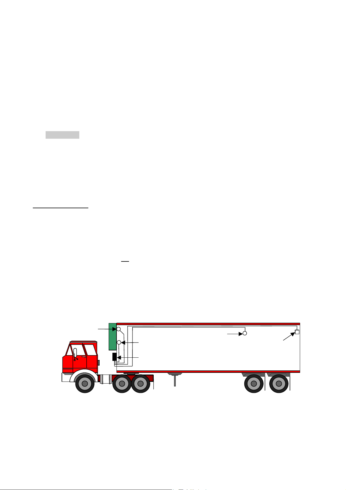
2.1 Positioning Connections
Temperature sensors
DataCOLD 500 T/R temperature recorders can only be used with temperature sensors supplied with the
DataCOLD 500 T/R package. Before the installation it is necessary to determine how many measurement points
are required to retrieve the desired information. Only by an optimal choice of the number and the position of the
sensors, can a sensible conclusion be drawn of the air temperature in an entire compartment.
The following items must be observed when planning:
- The Temperature sensor should not
- The sensor position should be protected against bumping of load, doors, etc..
- The beam of light from the interior light must have a minimum distance of 18 inches (0,5m) to the sensors.
- At least one sensor per compartment and also one sensor in the air return is recommended. The best position of
a compartment sensor is in the middle under the ceiling at about 1/3 of the compartment length from the back.
- The compartment sensor should be mounted with the Carrier protection guard. This will allow sufficient air
circulation around the sensor.
Supply air
sensor
be mounted in a location without air circulation.
Remote sensor
Return air sensor
DataCOLD T-version
Door switch
Page 5 62-61138-20 (02/03)

Digital Inputs
The digital inputs allow control and registration of doors (open/close) or defrost or refrigeration (on/off) or any other
digital input information following the configuration of the recorder. By configuring the parameters the interpretation
of the corresponding status can be distinguished.
Power supply
The power supply can be connected directly to the vehicle or Carrier Unit battery. The included 3A (T) floating fuse
must be fitted in the +power line direct as close as possible to the power connection. The DataCOLD 500 T/R
recorders are suitable for a voltage between 10 - 36 Volt DC.
2.2 Mounting
The installation set of the DataCOLD 500 T/R recorder contains almost all components, required for a standard
installation with two temperature sensors. In addition to that some small materials like Silicon kit, PVC-conduit and
fixing materials for cable mounting are required.
- Preferably use, for both outside and inside walls the existing cable conduit. Alternatively use self adhesive cable
conduit. All drilled holes needs to be sealed with a suitable sealant.
- For future calibration requirements, it is advisable to allow enough spare cable to enable the sensor to be lowered
to the floor.
DataCOLD R-Version
The R-version is designed to be mounted within the cab of a vehicle in a DIN radio slot. The R-version is retained
in the mounting cage by spring locking plates fitted to each side. Fix the mounting cage by inserting it into the slot
and bending the fixing blades to secure it in the facia. Slide the recorder into the cage until it locks into position.
Once fitted into the cage, the removal procedure is to insert the keys provided into the keyways at each side of the
front face of the recorder to release the locks.
1. Select a suitable position for the DataCOLD, for example a free car radio slot in the dashboard or above the
driver. If there is no free slot we recommend to use the optional mounting kit. The mounting kit can be fitted as
shown below on top or underneath the dashboard.
2. Next, push the mounting frame into the slot and bend the metal flaps to secure its position.
3. Then install the sensors from the body to the driver’s cab. Please make sure to fit the cables along the chassis
with the harness so that they won’t be broken when tilting the cab.
4. Take the connector blocks off the back of the instrument and fix the cables and connect the power supply
directly to the battery according to the wiring diagram section.
5. Finally, before pushing the instrument into the slot, we recommend to test the function and to do a printout.
Optional junction box
When installing more than two sensors in case of a R-Version it is recommended to use a junction box making the
installation simpler. This way of installation is using one multi-core cable to connect the recorder with the junction
box. Inside the junction box the individual sensors and digital inputs are connected. Because pin 1, 3, 5 and 7 of
the sensor inputs are linked via ground, only one of these pins needs to be connected. For the digital inputs the
same is applicable for pin 2, 4, 6 and 8.
Page 6 62-61138-20 (02/03)
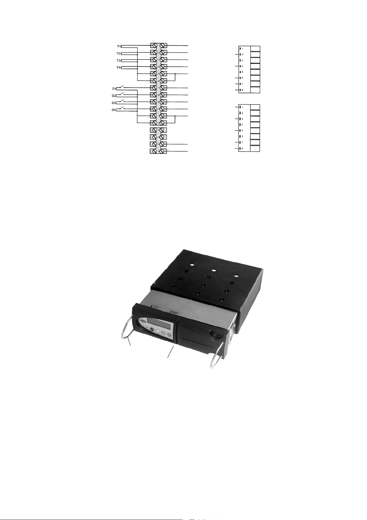
Temperature inputs
–
y
g
y
–
Di
ital inputs
12 Core cable
White
Lt. blue
Yellow
Pink Lt. Blue
Gre
Violet
Brown
Orange
Blue
Green
White
Yellow
Gre
Pink
Violet
Brown
Orange
CON4
Temperature inputs
Digitals inputs
CON3
Red
Black
Blue
Green
Optional Mounting kit
If no radio slot is available, the recorder should be mounted with the optional mounting kit. This will replace a radio
slot and can be fixed either on or under the dashboard as well as on the back wall.
Ensure that the position chosen allows the driver to see the display and operate the operator keyboard. In addition
it must be remembered that access to the printer drawer is required to replace the paper roll and this requires
clearance above the recorder.
Mounting enclosure
Key
DataCold R-Version
Page 7 62-61138-20 (02/03)
DataCOLD T-Version
The T-Version has been designed for outside mounting directly on the body. Usually it is fixed under the
refrigeration unit on the front side of the body, where it is easily accessible. For fixing proceed as follows: First hold
the box in the desired position and mark the mounting holes. Next step is to drill the holes so that the rubber
sleeves fit in exactly and the box can be screwed on.
Cables should be installed via watertight cable glands. This avoids moisture penetration into the box. For each
cable a separate gland should be used, unless you use a gland especially designed for more cables.
1. Mark the four holes at the front of body in an easily accessible location (usually underneath the refrigeration
unit to the right or left hand side). Then drill holes with a ∅ 25/64 inch (10mm) drill.
2. Insert the four rubber mounting nuts. Mount recorder using the four screws and washers provided (note metal
washer to be located on the outside of the mounting lug fixed to the box). Ensure screws are screwed in tight.
3. Drill hole large enough at suitable location through bulkhead to pass the temperature sensors through.
4. Connect power cable directly to the battery as described in the connection and wiring diagram section.
Recorder will start recording automatically.
5. Ensure all holes drilled through body are sealed with a suitable silicone sealer.
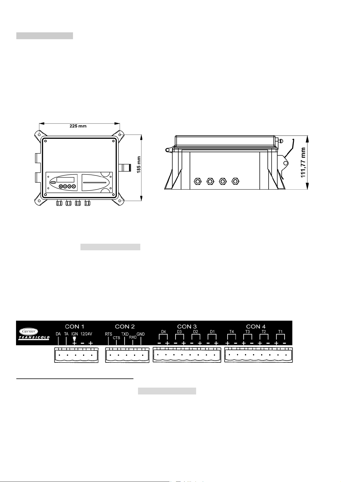
2.3 Connectors
Since both versions are provided with identical PCB’S, the connections are the same for both versions. On the
back of the recorder you will find four connector blocks . Each of them are described in detail in the next
paragraphs.
Connector CON 1 (Power supply and outputs)
- Power supply
Connect power supply on pin 1 (+) and pin 2 (-) directly to the battery. The recorder is suitable for a voltage
between 10 - 36 Volt DC. Power consumption when printing is 25W.
Page 8 62-61138-20 (02/03)

WARNING : DISCONNECT THE RECORDER FROM THE BATTERY IF THE REFRIGERATION UNIT
IS NOT USED FOR MORE THAN TEN (10) DAYS.
Page 9 62-61138-20 (02/03)
Loading...