


ZONEKIT4ZCAR
Comfort Zone
Installation and Start-Up Instructions
NOTE: Read the entire instruction manual before starting the installation.
TABLE OF CONTENTS |
|
PAGE |
|
Safety Consideration ...................................................................... |
1 |
Installation Considerations.......................................................... |
1-2 |
Introduction .................................................................................... |
2 |
Installation................................................................................. |
2-18 |
Check Equipment and Jobsite .................................................. |
2 |
Wiring........................................................................................ |
2 |
Shielded Cable..................................................................... |
2 |
Install Comfort Zone Center .................................................... |
3 |
Install Zone Dampers ............................................................ |
3-5 |
Round Metal Duct Work..................................................... |
4 |
Rectangular Metal Duct Work ............................................ |
4 |
Round Flexible Duct Work.............................................. |
4-5 |
Rectangular Fibrous Glass Duct Work ............................... |
5 |
Install Barometric Bypass Dampers ......................................... |
5 |
Install Duct Temperature Sensor .......................................... |
5-6 |
Install Dx Coil Sensor .............................................................. |
6 |
Install Four Zone Controller..................................................... |
6 |
Install Remote Room Sensor or Smart Sensors ...................... |
6 |
Comfort Zone System Wiring Diagram................................... |
7 |
Sequence Of Operation............................................................. |
6-12 |
Temperature Setpoints ......................................................... |
6 |
Heating and Cooling Comfort Setpoints..................... |
6 & 8 |
Sequence of Events For a Normal Heating |
|
or Cooling Cycle ............................................................ |
8 |
Selection of a Reference Zone In The System .................. |
8 |
Pre-positioning Dampers And Starting |
|
The System Fan................................................................ |
8-9 |
Controlling The Zone Dampers .......................................... |
9 |
Operating The Heating And Cooling Equipment............... |
9 |
Control Strategy For Heating/Cooling Stages............... |
9-10 |
Configuration Options For Equipment Operation ............ |
10 |
Relay Pack To HVAC Equipment Connections .............. |
10 |
Starting The HVAC Equipment .................................. |
10-11 |
Stage Control During Equipment Operation ............... |
11-12 |
Configuring Four Zone Controller.................................... |
12-13 |
Programmable Options Settings .................................. |
12-13 |
Programmable Options Toggles........................................ |
13 |
Wiring Diagram Reference Tables......................................... |
13 |
Start Up.............................................................................. |
13-14 |
Programming Schedules .................................................... |
14-16 |
System Switches........................................................... |
14-15 |
Controller Display ............................................................. |
15 |
Zone Selector Dial ....................................................... |
15-16 |
Accessories ........................................................................ |
16-17 |
Troubleshooting ...................................................................... |
17 |
Care And Maintenance ................................................................ |
17 |
Toggle Summary Table................................................................ |
18 |
Operating Problem Table ............................................................. |
19 |
Storage Failure Error Table ......................................................... |
20 |
COOL |
72 |
HEAT |
2:45 |
|
68 |
|
|
|
A93208 |
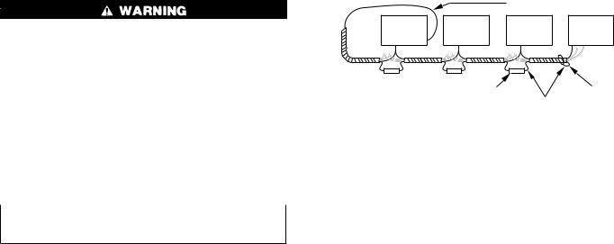
Fig. 1−Comfort Zone System |
|
Hardware Failure Error Table...................................................... |
21 |
Wiring Diagrams..................................................................... |
22-31 |
Configuration Table ..................................................................... |
32 |
SAFETY CONSIDERATIONS
Improper installation, adjustment, alteration, service, maintenance, or use can cause fire, electrical shock, or other conditions which may cause personal injury or property damage. Consult a qualified installer, service agency or your distributor or branch for information or assistance. The qualified installer or agency must use factory-authorized kits or accessories when modifying this product. Refer to the individual instructions packaged with the kits or accessories when installing.
Follow all safety codes and wear safety glasses. Have fire extinguisher available. Read these instructions thoroughly and follow all warnings or cautions attached to the unit. Consult local and state building codes and Sheet Metal and Air Conditioning National Association (SMACNA) for special installation requirements.
Recognize safety information. This is the safety-alert symbol . When you see this symbol on the unit or in instructions and manuals, be alert to the potential for personal injury.
Understand the signal words DANGER, WARNING, or CAUTION. These words are used with the safety-alert symbol. DANGER identifies the most serious hazards which will result in severe personal injury or death. WARNING signifies hazards which could result in personal injury or death. CAUTION is used to identify unsafe practices which would result in minor personal injury or product and property damage.
INSTALLATION CONSIDERATIONS
1.Install in a non-condensing area with ambients between 32°F and 120°F.
Manufacturer reserves the right to discontinue, or change at any time, specifications or designs without notice and without incurring obligations.
Book |
1 |
1 |
4 |
4 |
PC 101 |
Catalog No. 809-568 |
Printed in U.S.A. |
Form ZONEKIT4-1SI |
Pg 1 |
7-95 |
Replaces: 920415-3SI |
Tab |
3a |
5a |
2a |
5a |
|
|
|
|
|
|
|
2.Use vibration isolators (flex connectors) on zone dampers and duct work to minimize noise.
3.Place dampers away from areas that may be noise sensitive.
4.TXV is required in air conditioning and heat pump applications.
5.Use separate isolated transformer to supply power to Comfort Zone System (50 va minimum, class 2, field supplied).
6.Load calculations must be performed to determine equipment size. Equipment selection is matched to block load. It is imperative equipment is not oversized.
7.Duct work must be designed based off the sum of peaks plus 25 percent oversize. It is imperative duct work is not undersized.
INTRODUCTION
This installation guide pertains to revision 1.6 or greater. The Comfort Zone System allows air conditioning and heating equipment to control temperatures in up to 4 distinct spaces or Zones within a building. Each zone has independent temperature settings. The comfort temperature settings can change automatically through the use of schedules. This allows Comfort Zone to change temperature settings in zones to reflect occupancy or usage. For example, you can condition the bedrooms in a home from 5:00 PM through 7:00 AM or the kitchen from 3:00 PM through 6:00 PM. The Comfort Zone System uses motorized air volume control dampers (also called zone dampers) to regulate flow of conditioned air into zones. In this manner Comfort Zone can selectively heat or cool certain portions of a building depending upon space temperature requirements.
INSTALLATION
Step 1ÐCheck Equipment and Jobsite
INSPECT EQUIPMENT Ð File claim with shipping company, prior to installation, if shipment is damaged or incomplete.
Step 2ÐWiring
To prevent personal injury or possible equipment damage disconnect power supply before routing wire.
All wiring must comply with local and state codes.
NOTE: A remote room sensor requires a 2-wire cable, however, it is recommended that a 5-wire cable be installed to allow for a possible smart sensor upgrade. Connect white wire to terminal labeled B- if a 5-wire cable is used. Connect red wire to R+. Shielded cable is recommended to reduce noise interference.
NOTE: Use No. 22 AWG color-coded, insulated (35°C min) wire. If thermostats are to be located more than 100 ft from Comfort Zone Center as measured along control voltage wires, use 18 AWG colored-coded wires to avoid excessive voltage drop.
All wiring is run back to Comfort Zone Center. Keep wires a minimum of 12 in. from any AC voltage. Do not tie-wrap wires together. When wiring to COM BUS, a 3-wire cable must be separate from the 5-wire cable. The thermostats should be located approximately 5 ft above floor and must be located within 200 ft of Comfort Zone Center.
SHIELDED CABLE
General
1.All wiring should be shielded (except damper wiring) with 18 or 22 gage. The 3-wire, 5-wire, and Remote Sensor wire must be in separate jacketed cable.
2.All system wiring must be within 1 building. Never connect devices between 2 or more buildings.
Shielding For A Single Comfort Zone System
1.Fig. 16 Shows a Comfort Zone System with all possible options. The shield from all devices should be tied together at I/O board and terminated at shield ground at lower right hand corner of board. Be sure shielding does not touch any other wiring on board.
NOTE: Do not connect shield wire at device end. Cut end and tape up to avoid shorting.
Shielding For Multiple Comfort Zone Systems
1.If more than 1 Comfort Zone System resides on 1 job, they may be tied together for communication purposes. If no communication is required, then Comfort Zone System should be wired separate and shielded as previously stated.
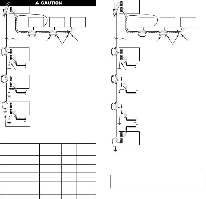
2.When 2 to 4 systems are on 1 job and require communication, they should be daisy chained together through 3-wire communication bus at COM BUS HAM terminal.The shielding should only be grounded at 1 point on end of communication bus as shown in Fig. 2.
|
|
SHIELD DRAIN WIRE |
|
Comfort |
Comfort |
Comfort |
Comfort |
Zone |
Zone |
Zone |
Zone |
I/O |
I/O |
I/O |
I/O |
|
|
NOTE 1 |
NOTE 2 |
|
|
SHIELD DRAIN WIRE |
|
NOTES:
1.Use butt splices, or solder, for shield connections. Then tape up shield.
2.Do not connect the shield drain wire at the end of Communication Bus. Cut and tape up to avoid shorting.
A93251
Fig. 2ÐDaisy-Chained Comfort Zone Systems
3.If more than 4 systems are used on 1 job, multiple device buses must be used. Each device bus must be separated by an ISOSAT-01. A typical arrangement is shown in Fig. 3.
Communication Bus Guidelines for Maximum Number of Devices
1.The maximum number of Comfort Zone Systems allowed on 1 device bus is 4.
2.Four Zone Controllers must be addressed 4 addresses apart, example 4, 8, 12, 16 for a device bus with 4 Comfort Zone Systems.
3.Home Access Module (optional) will scan a maximum of 4 Comfort Zone Systems.
4.Multiple device buses can be tied together for communication via ISOSAT-01. An ISOSAT-02 is required for remote or direct communications via personal computer or modem. (See Fig. 4.)
5.Comfort Zone Systems may reside on a bus with VVT system devices. They may receive or broadcast time to these devices accordingly by toggling T5 enable broadcast on or off.
NOTE: If multiple 4-zone controllers are on 1 bus, only 1 can broadcast time. Turn all others off (T5).
2
NOTE 2
PORT #1 |
|
|
|
|
|
|
|
PORT #2 |
ISOSAT-01 |
|
|
|
|
||
|
|
|
|
|
|
||
|
Comfort |
|
Comfort |
Comfort |
|||
|
Zone |
|
Zone |
|
Zone |
|
|
|
I/O |
|
I/O |
|
I/O |
|
|
ISOSAT BUS |
NOTE 1 |
|
NOTE 2 |
||||
|
|
|
|||||
PORT #1 |
|
|
SHIELD DRAIN WIRE (TYP) |
||||
|
|
|
|
|
|
||
PORT #2 |
ISOSAT-01 |
|
|
|
|
||
|
|
|
|
|
|
||
|
DEVICE BUS (TYP) |
|
|
|
|||
SHIELD DRAIN WIRE (TYP) |
|
|
|
||||
PORT #1 |
|
|
|
|
|
|
|
PORT #2 |
ISOSAT-01 |
|
|
|
|
||
|
|
|
|
|
|
||
|
|
|
NOTES: |
|
|
||
|
|
|
1. Use butt splices, or solder, |
||||
|
|
|
|
for shield connections. Then |
|||
|
|
|
|
tape up shield. |
|
||
PORT #1 |
|
|
2. Do not connect the shield |
||||
|
|
|
|||||
PORT #2 |
ISOSAT-01 |
|
drain wire at the end of |
||||
|
|
|
Communication Bus. Cut |
||||
|
|
|
|
||||
|
|
|
|
and tape up to avoid shorting. |
|||
|
BUILDING GROUND |
|
|
||||
|
|
|
|
|
|
A93249 |
|
Fig. 3ÐTypical Communications Network |
|||||||
Table 1ÐWiring Requirements |
|
||||||
FROM |
|
|
NO. |
|
|
MAX. |
|
COMFORT ZONE |
|
|
GAGE |
LENGTH |
|||
OF WIRES |
|||||||
CENTER TO |
|
(FT) |
|||||
|
|
|
|
||||
Four Zone Controller |
|
3³ |
|
18/22 |
200/100 |
||
|
5³ |
|
18/22 |
200/100 |
|||
|
|
|
|
||||
Remote Room Sen- |
|
2³ |
|
18/22 |
200/100 |
||
sors |
|
|
|
||||
|
|
|
|
|
|
||
Remote Duct Sensors |
|
2³ |
|
18/22 |
200/100 |
||
Dx Coil Sensor |
|
2³ |
|
18/22 |
200/100 |
||
Home Access |
|
3³ |
|
18/22 |
1000/100 |
||
Module |
|
|
|
||||
|
|
|
|
|
|
||
ISOSAT* |
|
|
3³ |
|
18/22 |
1000/100 |
|
Transformer² |
|
2 |
|
18 |
75 |
||
*When using ISOSATS in interfacing multiple buses together, the length of wiring between ISOSATS cannot exceed 4000 ft with 18 gage.
² 24 vac, 50-75 va
³ Shielded cable recommended to reduce noise interference.
Step 3ÐInstall Comfort Zone Center
NOTE: The Comfort Zone System is approved for indoor use only and should never be installed with any of its components exposed to the elements. The enclosure must be installed with center cover to help prevent damage from other sources. Do not mount Comfort Zone Center where it will be accessible to children. Do not locate center in areas of the home that are noise sensitive since relays are energized and de-energized during operation and may be an annoyance. Install Comfort Zone in an area with a temperature range between 32°F and 120° F.
Install Comfort Zone Center in either a vertical or horizontal position. Locate in an area that is easily accessible in case servicing should be required.
NOTE: Four vent plugs and 2 bushings have been supplied. Snap bushings in the 1-in. diameter holes that are to be used for wiring and place plugs in remaining holes.
NOTE 2
PORT #1
ISOSAT-01
PORT #2
|
Comfort |
Comfort |
Comfort |
|
Zone |
Zone |
Zone |
|
I/O |
I/O |
I/O |
ISOSAT BUS |
NOTE 1 |
NOTE 2 |
|
|
|
||
PORT #1 |
|
SHIELD DRAIN WIRE (TYP) |
|
|
|
|
|
PORT #2 |
ISOSAT-01 |
|
|
|
|
|
|
DEVICE BUS (TYP)
SHIELD DRAIN WIRE (TYP)
|
|
|
|
|
PORT #1 |
ISOSAT-01 |
|
|
|
|
|
||
|
|
|
|
|
PORT #2 |
|
|
|
|
|
|
||
|
|
|
|
|
||
|
|
|
|
|
|
|
|
|
|
|
|
|
|
|
|
|
|
|
|
|
|
|
|
|
|
|
|
|
|
|
|
|
|
|
|
|
|
|
|
|
|
|
|
|
PORT #1 |
ISOSAT-01 |
|
|
|
||
|
|
|
PORT #2 |
|
|
|
|
||
|
|
|
||
|
|
|
|
|
|
|
|
|
|
|
|
|
|
|
NOTES:
1.Use butt splices, or solder, for shield connections. Then tape up shield.
2.Do not connect the shield drain wire at the end of Communication Bus. Cut and tape up to avoid shorting.
TO PERSONAL COMPUTER OR MODEM
PORT #1
ISOSAT-02
PORT #2
BUILDING GROUND
Fig. 4ÐCommunication Network With A93250
An ISOSAT-02
To prevent possible damage to Comfort Zone Center, do not mount on plenum, duct work, or flush against furnace.
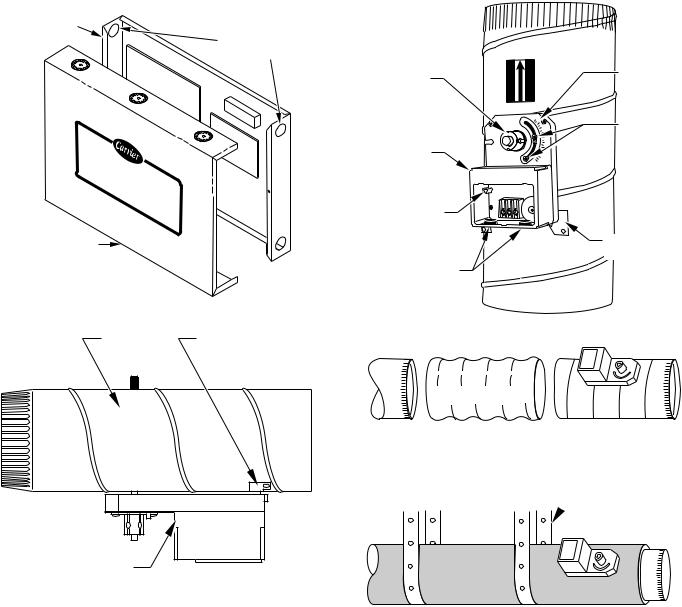
1.Separate Comfort Zone Center cover. (See Fig. 5)
2.Mount back plate of center cover to wall using screws and wall anchors provided.
3.Level back plate and tighten screws.
Step 4ÐInstall Zone Dampers
IMPORTANT: If conditions exist for possible condensing, motor must be positioned for adequate draining. (See Fig. 6.)
NOTE: If a multi-damper enabler is used to link dampers together, add 5va per damper to the transformer power supply rating. Reference multi-damper enabler Installation Instructions.
Zone dampers may be installed in any direction.
Install dampers so that actuator is visible for inspection and accessible in the event it would ever need to be serviced. The black mark on the end of damper shaft represents the position of damper blade.
NOTE: Insulate damper using 1-1/2 in. insulation (check local codes). In areas where excessive condensing may occur, carefully insulate over the actuator assembly. Make sure insulation does not interfere with operation of actuator.
3
COMFORT ZONE CENTER
BACK PLATE
INTERCHANGEABLE HOLE PLUGS AND
BUSHINGS
Comfort |
Zone |
|
|
Center |
|
COMFORT ZONE
CENTER COVER
A93247
Fig. 5ÐComfort Zone Center
DAMPER MOUNTING
BRACKET
|
AIRFLOW |
AIRFLOW |
INDICATOR |
MOUNTING |
|
|
POSITION |
HUB |
|
|
|
|
|
90 |
ANGULAR |
|
|
|
|
|
|
45 |
ROTATION |
ACTUATOR |
|
|
STOPS |
|
|
|
|
HOUSING |
|
0 |
|
|
CLS COM OPN |
|
|
QUICK BLADE |
|
|
|
RELEASE |
|
|
|
BUTTON |
|
|
MOUNTING |
(RED) |
|
|
|
|
|
|
BRACKET |
FIELD |
|
|
|
INSTALLED |
|
|
|
POWER WIRING |
|
|
|
|
|
|
A95096 |
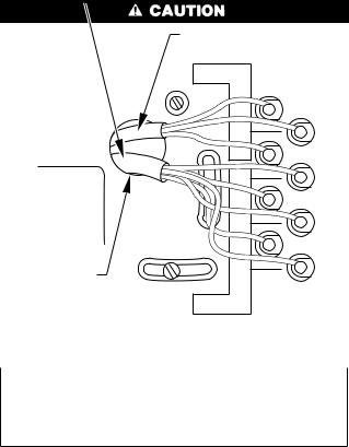
Fig. 7ÐDamper 24-vac Connections |
|||
ACTUATOR |
A95128
Fig. 6ÐDamper Motor Positioning
Before insulating the duct work, check for proper damper operation. Apply the 24vac between COM and OPN to open the damper and COM and CLS to close the damper. (See Fig. 7.) The damper will modulate counter-clockwise to open and clockwise to close.
If in an emergency it becomes necessary to force a damper open, manually press in the red quick blade release button with one hand and turn the mounting hub to reposition the damper shaft. Release the button to hold the damper shaft in the new position.
To avoid noise and vibration, do not hard mount dampers to any solid structure such as joists.
ROUND METAL DUCT WORK
IMPORTANT: If application exists with all metal duct work without insulation, flex connectors must be used on each end of zone dampers to avoid noise and vibration.
1.Crimp end of branch duct.
2.Slip end of zone damper over end of duct work. Use self-tapping sheet metal screw to secure. (See Fig. 8.)
3.Properly seal joint using duct tape, mastic, or other approved method. Do not allow mastic to come in contact with actuator.
4.Insulate damper using 1-1/2-in. to 2-in. insulation. (Check your local codes.)
SUPPLY FLEX ZONE DAMPER CONNECTOR
A95129
Fig. 8ÐRound Metal Duct Work
 1/2 ² STEEL STRAP
A95130
Fig. 9ÐInsulated Round Metal Duct Work
NOTE: All zone dampers and duct work must be properly supported according to local codes or SMACNA standards.
RECTANGULAR METAL DUCT WORK
1.Make connections using S-lock and drives. (See Fig. 10.)
2.Properly seal joint using duct tape, mastic, or other approved method. Do not allow mastic to come in contact with actuator.
3.Insulate damper using 1-1/2-in. to 2-in. insulation. (Check your local codes.)
NOTE: All zone dampers and duct work must be properly supported according to local codes or SMACNA standards.
NOTE: There should be a minimum of 4 ft between zone damper and first branch duct if more than 1 branch duct is downstream of zone damper.
ROUND FLEXIBLE DUCT WORK
1.Slip 1 end of flexible duct work over 1 end of zone damper. (See Fig. 12.)
4
 S-LOCK
SUPPLY
AIR DUCT
DRIVE |
ZONE |
|
DAMPER |
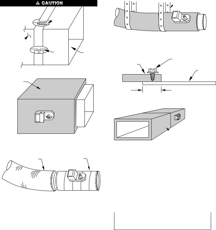
Fig. 10ÐRectangular Metal Duct Work A92478
1 1/2 " TO 2" INSULATION
A95131
Fig. 11ÐInsulated Rectangular Metal Duct Work
FLEXIBLE |
ZONE |
DUCT |
DAMPER |
A95132
Fig 12ÐRound Flexible Duct Work
2.Secure flexible duct to zone damper using SMACNA or other approved method.
3.Properly seal joint using duct tape, mastic, or other approved method. Do not allow mastic to come in contact with actuator.
4.Insulate damper using 1-1/2-in. to 2-in. insulation. (Check your local codes.)
NOTE: All zone dampers and duct work must be properly supported according to local codes or SMACNA standards.
RECTANGULAR FIBROUS GLASS DUCT WORK
1.Insert 1 end of zone damper into 1 end of fibrous glass duct work approximately 2- to 3-in. (See Fig. 14.)
2.Screw field-supplied screws and tabs into zone damper.
3.Properly seal joint using duct tape, mastic, or other approved method. Do not allow mastic to come in contact with actuator.
4.Insulate damper using 1-1/2-in. to 2-in. insulation. (Check your local codes.)
 1/2 ² STEEL STRAP
A95133
Fig. 13ÐInsulated Round Flexible Duct Work
FIBROUS
GLASS |
FIELD |
|
SUPPLIED |
||
DUCTWORK |
||
SCREWS |
||
|
||
|
ZONE |
|
|
DAMPER |
2² TO 3²
A92480
Fig. 14ÐRectangular Fibrous Glass Duct Work
 1 1/2 ² TO 2²
INSULATION
A95134
Fig. 15ÐInsulated Rectangular Fibrous Glass Duct Work
Step 5ÐInstall Barometric Bypass Damper
NOTE: The barometric bypass damper is a critical part of Comfort Zone System for control of minimum airflow and noise reduction. It is recommended that the bypass be installed.
The bypass should be installed according to local codes and SMACNA standards. Be sure bypass is properly supported.
For proper installation, refer to Installation Instructions packaged with barometric bypass.
Failure to properly install bypass damper can cause permanent damage to the HVAC equipment. For single speed furnace applications bypass air must never exceed 25 percent.
Step 6ÐInstall Duct Temperature Sensor
Locate duct temperature sensor in main supply trunk after heating and cooling coil and before bypass damper and first branch. The duct temperature sensor must be radiant shielded to prevent heat from affecting correct air temperature.
1.Drill a 7/8-in. hole at location in unit where sensor will be installed.
2.Remove cover and insert sensor probe through 7/8-in. hole.
3.Drill two 1/16-in. holes to accept No. 6 screws through pre-drilled holes in duct temperature sensor back plate.
4.Use two No. 6 sheet metal screws included with sensor to mount duct temperature sensor back plate to unit.
5
5.Insert 2-conductor wiring through 1 of pre-drilled holes in side of back plate.
6.Connect sensor to 2-wire conductor using provided wire nuts. (See Fig. 16 for connection to Comfort Zone Center.)
Step 7ÐInstall Dx Coil Sensor
The Dx coil temperature sensor is recommended for use in heat pump with fan coil applications only. The sensor should be installed between Dx coil and electric heaters. It measures Dx coil temperature and adds extra protection for high/low temperature limits. The range is from 30°F to 180°F. The Dx coil sensor interfaces to Comfort Zone Center on terminal TB-1. (See Fig. 16.) To activate Dx coil temperature sensor turn T-27 on. When activated, the Dx coil sensor has built-in LAT setpoints of 50°F and 45°F in the cooling mode, and 105°F and 110°F in the heating mode. This is non-adjustable.
Step 8ÐInstall Four Zone Controller
The Four Zone Controller is the zone 1 thermostat. It is recommended to locate this in the zone occupied as the living room or family room for maximum comfort.
DO NOT locate controller where supply air can blow directly on it. Avoid locating controller where heat from any lamps, appliances, or direct sunlight will affect temperature sensor on controller. Do not locate on an outside wall or next to a return air grill.
1.Separate base plate from main body of controller.
2.Pull 3-wire cable for communication bus and 5-wire cable for controller through 3/4-in. round hole on base plate. Three-wire cable and 5-wire cable must be separate jacketed wiring. Do not use one 8-wire cable. (See Fig. 17.)
NOTE: Insulate or seal field wiring feed through hole to reduce draft.
3.Mount base plate using provided screws, starting screw in round hole first then second screw in slotted hole. On drywall it is recommended to use provided plastic wall anchors.
NOTE: If mounting controller using an electrical box, mount base plate using pair of horizontal holes.
4.Level base plate and tighten screw in slotted hole first, then the screw in round hole.
5.Connect the 3 wires for communication bus and the 5 wires for controller to base plate terminal screws. (See Fig. 16.) Ensure that there are no excess or bare wires exposed.
6.Plug base plate connector into back of main body and ensure it is secure into connector located on back of 4 zone controller's main body. Ensure connectors and main body are secure.
7.Align main body with base plate and snap into place.
Step 9ÐInstall Remote Room Sensors or
Smart Sensors (Optional)
Comfort Zone may have up to 4 zones. The 4 zone controller controls zone 1. Remote room sensors or smart sensors control the other 3 zones. If using a smart sensor, a smart sensor power pack must be used. The remote sensors should be located 5 ft above the floor and must be less than 200 ft away from Comfort Zone Center.
DO NOT locate sensors where supply air can blow directly on them. Avoid locating sensors where heat from any lamps, appliances, or direct sunlight will affect temperature sensor on room sensors. Do not locate on an outside wall or next to a return air grill.
1.Separate the 2 parts of sensor and mount back plate with provided flat-head screw.
2.Pull a 2-wire conductor through hole on right-hand side.
3.Connect black or white wire to terminal labeled B- and connect red wire to terminal labeled R+.
4.Align sensor case with base plate then press firmly until cover snaps into place.
Step 10ÐSequence of Operation
TEMPERATURE SETPOINTS
The Comfort Zone System uses 2 temperature setpoints. The setpoints are displayed in the left-hand window on the 4 zone controller. (See Fig. 18.)
In display window, cooling setpoint is shown on upper left and heating setpoint is shown on lower right.
The temperature setpoints for any of the 4 zones can be displayed by the 4 zone controller. When the 4 zone controller rotary switch points to zone 1, setpoints for zone 1 at the 4 zone controller are displayed. Selecting zone 2, zone 3, or zone 4 will display setpoints for each of these zones which use either remote room sensors or smart sensors. The system is not required to have all 4 zones installed.
HEATING AND COOLING COMFORT SETPOINTS
If space temperature is between heating and cooling setpoints for the zone, then the zone is said to be "satisfied" with respect to temperatures. When a zone is "satisfied" no heating or cooling equipment will turn on to condition the space. For example, if cooling setpoint is 76°F and heating setpoint is 72°F, then a space temperature of 73°F is assumed to be satisfactory and no heating or cooling of zone is required.
If space temperature in a zone falls below heating setpoint, then that zone needs to have heat added to zone which will raise space temperature back to heating setpoint. For example, if heating setpoint is 72°F and space temperature is 70°F, then space temperature must be raised 2 degrees in order for zone to be satisfied. In this case, temperature "heating demand" for zone is 2°F. (72°F minus 70°F.)
Otherwise, if space temperature in a zone rises above cooling setpoint, then that zone needs to have heat removed from zone which will lower space temperature back to cooling setpoint. For example, if cooling setpoint is 76°F and space temperature is 77°F, space temperature must be lowered 1° in order for zone to be satisfied. In this case, "cooling demand" for zone is 1°F. (77°F minus 76°F.)
Comfort Zone allows owner or installer to set ranges for comfort setpoints along with maximum and minimum temperatures which can be used by system.
Comfort Zone allows both heating and cooling comfort setpoints to operate in a 14° span. The heating and cooling temperature "spans" can be set to allow for a selected range of operation. Rotary switch position 9 sets base temperatures for both heating and cooling spans.
When switch is set to 9, both heating and cooling base temperatures are displayed and each can be modified by using up/down setpoint buttons. The base temperatures are the same for all 4 zones.
If cooling base temperature is set to 68°F, then cooling comfort range will be 68°F to 82°F. If heating base temperature is set to 54°F, then heating comfort range will be 54°F to 68°F.
6

Zone Dampers
|
|
|
24 VAC Transformer |
|
|
|
|
|
|
|
|
|
|
(Field Supplied) |
|
|
|
To |
|
|
|
|
|
|
50 VAC req. for basic |
|
|
|
|
|
|
|
|
|
|
4 damper system. Please |
|
|
HVAC |
|
|
|
|
|
|
|
see Page 1, Electrical |
|
|
System |
|
|
|
|
|
|
|
Rating for details. |
|
|
|
|
|
|
|
|
|
|
#16 AWG to |
|
|
|
|
|
|
|
|
|
|
Grounded to Water Pipe |
|
|
|
|
|
|
|
|
|
|
or Solid Electrical Ground |
(0)COOLRV OR |
(G) FAN |
(W2)2 HEAT |
(W1)1 HEAT |
(Y2)2 COOL |
(Y1)1 COOL |
VAC24 UNIT |
|
|
|
(B)HEATRV |
|||||||
BYPASS |
ZN4 ZN3 ZN2 |
ZN1 |
PWR. 24VAC |
|
|
|
|
|
|
|
|
|
|
|
|
|
|
|
|||
CL OP COM |
CL OP COM CL OP COM CL OP COM |
CL OP COM |
|
|
|
|
|
|
|
|
|
|
|
|
|
|
|
|
|
|
(R) |
|
|
|
CHR06 PWR |
|
Power |
|
|
|
|
RELAY |
SYSTEMCONTROLLER |
|
|
BUS HAM |
CONTROLLER |
|
|
CHR06 W G B Y R |
CHR-06 |
|
COMFORT ZONE I/O |
|
|
|
|
|
|
COMM |
COMM BUS |
|
|
|
|
|
W R G |
W R G |
R W R W R W R W R W R W |
SHIELD |
|
|
|
|
|
DX OAT LAT ZT4 ZT3 ZT2 |
GROUND |
|
|
|
|
|
|
|
|
72 |
2:45 |
|
|
|
|
|
|
68 |
|
|
|
|
Zone 2* |
|
|
|
|
|
|
|
|
4-Zone Controller |
|
|
|
|
Zone 3* |
|
|
|
|
|
|
Zone 4* |
Zone 1 |
|
Dx Coil |
Outside Air |
Duct |
Remote Room |
|
|
|
Sensor |
Sensor |
Sensor |
Sensors |
Communication Bus |
||
(optional) |
(optional) |
|
|
|
||
|
|
|
|
|
||
Custom Cable
CALLOUT TO PHONE PHONE LINE |
POWER |
COMM BUS |
|
|
|
|
B Y G W R |
B Y G W R |
B Y G W R |
Home Access Module |
Smart Sensor Power Pack |
|||
(optional) |
|
(optional) |
|
|
*It is recommended that a 5 wire cable be used to install
Remote Room Sensors to allow
for future upgrade to Smart Sensors.
Smart Sensor
(optional)
A94311
Fig. 16ÐComfort Zone System Wiring Diagram
7
5 WIRE CONDUCTOR
(INTERFACE BOARD)
3 WIRE CONDUCTOR
(COMM BUS)
COMM BUS
GRN |
GREEN |
RED |
RED |
|
|
WHT |
WHITE |
|
|
RED |
RED |
|
|
YEL |
YELLOW |
|
|
BLU |
BLUE |
|
|
GRN |
GREEN |
WHT |
WHITE |
FIELD WIRING |
|
(FEED THRU) |
|
I/O BOARD |
|
Fig. 17ÐWiring Four Zone Controller A93231
Changing the base temperatures will change the Comfort Temperature Setpoints used in the system schedules. Always set the Base Temperatures prior to programming the system schedules.
Comfort Zone also uses a minimum temperature and a maximum temperature for comfort setpoints. The minimum and maximum temperatures are the same for all 4 zones.
The Maximum Temperature is only used for cooling. It is set by selecting Rotary Switch Position S-2. The Maximum Temperature setting is used when a temperature above the 14° span is selected. If Cooling Base Temperature is set to 68°F and cooling setpoint is 82°F, any attempt to raise cooling setpoint will select Maximum Temperature.
The Minimum Temperature is only used for heating. It is set by selecting Rotary Switch Position S-3. The Minimum Temperature setting is used when a temperature below the 14 ° span is selected. If Heating Base Temperature is set to 54°F, any attempt to lower heating setpoint below 54°F will select Minimum Temperature.
Both Maximum and Minimum Temperatures are intended for use with schedules or setpoints which are extreme compared to normal building temperatures.
Comfort Zone also has one additional set of temperature settings. These are Vacation Setpoints. The Vacation Setpoints are heating and cooling setpoints to be used in all 4 zones whenever 4 zone controller rotary switch is turned to "Vacation." The Vacation option is used to place entire building in setback during long unoccupied periods without danger of freezing or extreme heat/humidity.
SEQUENCE OF EVENTS FOR A NORMAL HEATING OR COOLING CYCLE
Given Comfort Setpoints and space temperature for zones within system, Comfort Zone will determine if active heating or cooling is required. If so, Comfort Zone will perform the following:
1.Select a reference zone.
2.Make sure all zone dampers are fully open.
3.Energize HVAC equipment fan.
4.Energize heating or cooling equipment. The equipment may be a compressor, furnace, strip heater, etc.
5.Set the zone damper positions based upon zone demand.
6.Energize additional stages of heating or cooling if demand warrants.
7.Continue to adjust zone dampers as conditions within zones change.
8.Turn off heating or cooling equipment when all zones are within 0.5°F of desired comfort setpoint.
9.Open all zone dampers when equipment is turned off.
This is the basic Sequence of Operation for the Comfort Zone system. The actual control of dampers, HVAC equipment, and system fan will change with configuration of system. Depending upon configuration, Comfort Zone can control heat pumps, furnaces, and dual fuel applications.
SELECTION OF A REFERENCE ZONE IN THE SYSTEM
The first step in any heating or cooling cycle requires Comfort Zone to evaluate zones, determine if heating or cooling is needed, and select a Reference Zone.
The Comfort Zone system actively looks at Comfort Setpoints and space temperature in all zones. If any zone in system has a demand of 1.5°F or more, then Comfort Zone will prepare to operate heating or cooling equipment to reduce demand.
First, Comfort Zone will select a reference zone in the system. The reference zone will be zone with greatest demand. The zone damper serving reference zone will be forced fully open and will remain fully open as long as that zone is used as reference.
As long as any zone in system has a demand greater than or equal to 1.5°F, then Reference Zone will be selected by zone with greatest demand. Once all zones have a demand less than 1.5oF, Reference Zone selection will not change until demand in that zone is below 0.5°F. At this point Comfort Zone will re-select Reference Zone and position that particular zone damper fully open.
The objective of Reference Zone is to ensure that zone with greatest demand is receiving as much conditioned air as system will allow. It also gives Comfort Zone system a point of reference in observing response of zones to equipment operation.
PRE-POSITIONING DAMPERS AND STARTING THE SYSTEM FAN
In order to minimize noise and enhance system operation, Comfort Zone maintains all zone dampers full open prior to starting system fan or heating or cooling equipment. The intent is to provide HVAC equipment with unrestricted duct work and reduce pressure surges. Comfort Zone also fully opens dampers whenever a heating or cooling cycle is completed and system fan is shutting down. If Fan Switch on 4 zone controller is set to Auto, then all zone dampers will remain fully open until next heating or cooling cycle.
The other reason for opening dampers is to provide unrestricted duct work to other equipment which is not directly controlled by Comfort Zone. One example may be Heat Recovery Ventilator. If Comfort Zone is not actively controlling HVAC system, then it must not impose any control influences (i.e., closed zone dampers) on system and prevent proper operation of other devices.
For Fan operation, switch settings on 4 zone controller and system configuration can change actual operation.
If Auto Fan Off For Heating option (Rotary switch position number T-9) is ON, then Comfort Zone will only energize fan for cooling cycles. This option is intended for furnaces which will control their own fan internally.
8
If Fan Switch on 4 zone controller is set to ON instead of Auto, then system fan will run continuously. Any time Comfort Zone is operating fan, it will be in active control of system.
NOTE: If Auto Fan Off For Heating option (rotary switch position T-9) is ON, and Fan Switch on the 4 zone controller is ON, Comfort Zone will operate fan full time.
Operating fan continuously will place Comfort Zone in a Float Mode any time no active heating or cooling is taking place. During Float Mode, Comfort Zone will position zone dampers based upon demand in each zone. Comfort Zone will check air temperature in duct work and allow air into zones if it will help zones reduce their individual demands. For example, if temperature of air in duct work is 65°F, cooling comfort setpoint for a zone is 72°F, and space temperature is 73°F, then Comfort Zone will open damper servicing that zone and allow cooler air into space.
Ventilation Mode is only in effect when temperature of supply air is between 65°F and 80°F. Ventilation Mode establishes minimum position of zone dampers and is intended to help air movement throughout zones and reduce chance of having areas which are stagnant or have high humidities with respect to rest of system. The changes to dampers are detailed in the next section "Controlling the Zone Dampers."
CONTROLLING THE ZONE DAMPERS
The zone dampers have a total of 16 possible positions or increments which are numbered 0 (zero) through 15. Position number 0 is fully closed and position number 15 is fully open. While damper servicing reference zone remains fully open, all other zone dampers are positioned by selecting a position equal to demand of space in tenths of a degree. (See Table 2.)
Table 2ÐZone Damper Positions Damper Position Versus Zone Demand
DAMPER |
DEMAND °F |
DEMAND °C |
|
POSITION |
|||
|
|
||
0 |
0 |
0 |
|
Fully Closed |
|||
|
|
||
1 |
0.1 |
0.06 |
|
2 |
0.2 |
0.11 |
|
3 |
0.3 |
0.17 |
|
4 |
0.4 |
0.22 |
|
5 |
0.5 |
0.28 |
|
6 |
0.6 |
0.33 |
|
7 |
0.7 |
0.39 |
|
8 |
0.8 |
0.44 |
|
9 |
0.9 |
0.50 |
|
10 |
1.0 |
0.55 |
|
11 |
1.1 |
0.61 |
|
12 |
1.2 |
0.67 |
|
13 |
1.3 |
0.72 |
|
14 |
1.4 |
0.78 |
|
15 |
1.5 |
0.83 |
|
Fully Opened |
|||
|
|
For example, a zone which has a 1.0°F demand will have damper set to position number 10 while a zone which has a demand of 0.5°F will have damper set to position number 5. A demand of 0 (zero) will fully close zone damper. Any zone which has a demand greater than 1.5°F will remain fully open.
Notice that positions are based upon tenths of a degree Fahrenheit. If Comfort Zone has Celsius Temperature Display option (rotary position T-2) turned on, the damper control is still based upon Fahrenheit scale.
The damper positions in table are also used during a Float Mode. A zone with a demand of 0.5°F will be set to position number 5.
The actual control of zone dampers by Comfort Zone system can be modified using 3 configurable options. These are Maximum Damper Position, Minimum Damper Position, and Ventilation Mode.
These options apply to all zone dampers simultaneously. Any dampers servicing Zone 1 cannot be configured differently than those servicing Zone 2. The options are as follows:
1.The Maximum Damper Position (rotary position number S-4) sets maximum open damper position for all 4 zones. The allowable range for this option is damper positions number 8 through number 15 (fully open). The factory default is 15. The only time zone dampers will exceed this position is if system fan is off or zone dampers are being calibrated.
2.The Minimum Damper Position (rotary position number S-5) sets minimum open damper position for all 4 zones. The allowable range for this option is damper positions number 0 through number 7. The factory default is number 0 (fully closed). If Ventilation Mode (rotary position T-25) is turned OFF, then minimum damper position will be an absolute minimum regardless of operating mode. If Ventilation Mode is turned ON, then minimum damper position will be minimum position during a Ventilation Mode only and dampers will be allowed to fully close at any other time.
3.Ventilation Mode (rotary position T-25). If Ventilation Mode is turned ON, then any time air inside supply air duct work is between 65°F and 80°F, system will be in a "Ventilation Mode". During a Ventilation Mode all zone dampers will have a minimum position which is set by Minimum Damper Position (rotary position S-5). The zone dampers are not allowed to fully close as long as supply air temperature remains within the 65°F-80°F range. If supply air temperature falls outside the 65°F-80°F range, then zone dampers may fully close.
NOTE: If Ventilation Mode option (rotary position T-25) is turned ON, and Minimum Damper Position (rotary position S-5) is set to position 0, there is no difference between Float Mode and Ventilation Mode. In other words, Ventilation Mode option has no effect on system.
OPERATING THE HEATING AND COOLING EQUIPMENT
Before any heating or cooling equipment is started, Comfort Zone must first choose between heating or cooling. For most of the year there is little question as to the need for heat or cooling. But for portions of the year, particularly during mid-season, a building may have simultaneous needs for both heating and cooling.
The first step in selecting heating or cooling is the determination of a Reference Zone. If there is a single zone which has greatest demand, then it will become the Reference Zone and Comfort Zone will start equipment based upon needs of that zone. If 2 zones have same "greatest demand" but in different modes (1 needs heating and the other needs cooling), then Comfort Zone will select mode which has greatest number of zones which require same mode.
CONTROL STRATEGY FOR HEATING / COOLING STAGES
The Comfort Zone system will attempt to minimize use of additional stages of heating or cooling equipment. In an ideal case, building conditioning needs can be supplied by first stage cooling or first stage heating alone.
For most heat pump applications, there may be only 2 or 3 stages of heat depending upon type of emergency heater present. For a heat pump, secondary heat source will generally be an electric strip
9

Table 3ÐHeating System Option Vs. Type of Heater Used
HEATER TYPE USED |
HEAT PUMP |
TWO STAGE |
DUAL FUEL |
FAN ON |
|
FOR COOLING ONLY |
|||||
SYSTEM TOGGLE: |
HEAT PUMP |
SYSTEM SWITCH: |
|||
IN SYSTEM |
TOGGLE: |
||||
T-6 |
TOGGLE: T-26 |
S-7 |
|||
|
T-9 |
||||
|
|
|
|
||
Single-Stage Heat Pump |
On |
Off |
0oF (off) |
Off |
|
Two-Stage Heat Pump |
On |
On |
0oF (off) |
Off |
|
Heat Pump/Furnace Dual |
On |
Off |
10 to 60oF |
Off |
|
Fuel |
|
|
|
|
|
Two-Stage Heat Pump, |
On |
On |
0°F |
Off |
|
Furnace Dual Fuel* |
|||||
|
|
|
|
||
|
|
|
|
|
|
Furnace Heat Only |
Off |
Off |
0oF (off) |
On or Off |
|
Strip Heater Only |
Off |
Off |
0oF (off) |
Off |
* Refer to 2-speed heat pump Installation and Start-Up Instructions for details regarding 2-speed heat pump operation. It is recommended that heat pump control board controls operation of this equipment and not Comfort Zone.
Table 4ÐAvailable Heating and Cooling Stages Vs. System Type
TYPE OF HVAC |
COOLING STAGE 1 |
COOLING STAGE 2 |
HEAT STAGE 1 |
HEAT STAGE 2 |
HEAT STAGE 3 |
HEAT STAGE 4 |
|
EQUIPMENT USED |
|||||||
|
|
|
|
|
|
||
|
|
|
|
|
|
|
|
Cooling Only, any Heater Type |
Y1 |
Y2 |
W1 |
W2 |
-- |
-- |
|
|
|
|
|
|
|
|
|
Single-Stage Heat Pump |
Y1 |
-- |
Y1 |
W1 |
W2 |
-- |
|
Two-Stage Heat Pump |
Y1 |
Y2 |
Y1 |
Y2 |
W1 |
W2 |
|
|
|
|
|
|
|
|
For cooling applications, the second stage of an air conditioner is not necessarily more expensive to operate than first stage. But additional cooling can drive down the efficiency of a 2-speed air conditioner and longer use of first stage alone tends to deliver better humidity control in moist climates. Again, because of these advantages, Comfort Zone will attempt to minimize use of second stage cooling. This is not as great of a concern for a heating application, because the majority of small air conditioning systems sold today (5 tons and below) are single-stage cooling only.
heater. The electric strip heat is much more expensive to operate when comparing cost per unit of heat. Because auxiliary stages of heating tend to be more expensive to operate, Comfort Zone attempts to keep number of stages at a minimum.
CONFIGURATION OPTIONS FOR EQUIPMENT OPERATION
Comfort Zone has several configurable options which allow it to control different types of HVAC equipment and change the manner in which the equipment is controlled. This first group must be set given the type of HVAC equipment installed. These include:
1.Heat Pump Operation (Rotary Position T-6).
2.Two-Stage Heat Pump (Rotary Position T-26).
3.Dual Fuel trip temperature (Rotary Position S-7).
4.Auto Fan Off For Heat (Rotary Position T-9).
The second group modifies the way the HVAC equipment is controlled. These include:
1.Comfort Trend Staging (Rotary Position T-8).
2.System Mode Reselect (Rotary Position T-22).
3.High/Low Temperature Limits Enabled (Rotary Position T-10).
4.High Temperature Trip Limit (Rotary Position S-6).
5.Dx Sensor (Rotary Position T-27).
6.Smart Start (Heat Pump Strip Heat Economy Feature)
The first options which must be set are based upon the type heater or heaters used. These are shown in Table 3. The only option which appears to impact cooling operation is Two-Stage Heat Pump which implies the availability of 2 stages of cooling. In reality there are no changes to cooling control scheme.
Comfort Zone assumes that there are always 2 stages of cooling present. These are connected to the Comfort Zone Relay Pack on the Y1 and Y2 contacts.
RELAY PACK TO HVAC EQUIPMENT CONNECTIONS
Given system configuration, Comfort Zone can determine number of heating stages that it will actually control and which relay outputs will be used to control each stage of heat. Comfort Zone can control up to 4 stages of heat depending upon system configuration.
For cooling only applications with any type of heater, Comfort Zone will only control 2 stages of heat. If system uses a heat pump, then Comfort Zone will control 3 stages of heat. The additional stage is heat pump compressor contact. The auxiliary heat is still 2 stages. If system uses a 2 stage heat pump, then Comfort Zone will control 4 stages of heat, 2 stages for heat pump and 2 stages for auxiliary heat.
The Comfort Zone Relay Pack outputs are shown in Table 4. The Y1 and Y2 contacts are used for compressor contacts only. Comfort Zone operates heat pumps by energizing compressor contacts and controlling reversing valve through Reversing Valve (RV) relay output. The W1 and W2 contacts are always used for heat sources. These are heating only units such as furnaces, strip heaters, etc. The relay outputs for Comfort Zone 1.4 are shown in Table 4.
Under no circumstances may the W1 and Y1 contacts on the relay pack be jumpered together. This is a common practice for many heat pump installations but will cause improper operation of the Comfort Zone (1.4 or greater) system.
STARTING THE HVAC EQUIPMENT
Once Comfort Zone selects a mode, controller will use configuration options to modify control of HVAC equipment. The controller first selects number of stages of heating and cooling that may be applied to building load. The "available" stages are determined by Reference Zone temperature demand and are shown in Table 5.
Using Table 5, if Reference Zone has a 2.3°F demand, then Comfort Zone may use 2 stages of cooling or 2 stages of heating. The HVAC equipment may not have 3 stages of heat or even 2 stages of cooling. The table is only used to determine what equipment Comfort Zone is allowed to turn on at any given time during a heating or cooling cycle. Actual operation of stages depends on other variables as well.
Normally Comfort Zone will start equipment operation when it has a demand of 1.5°F or greater. In some cases, Comfort Zone will be facing a demand greater than 1.5°F when a mode is starting. This can occur when user changes setpoints in a zone or if a schedule
10 change has reset the Comfort Setpoints.
 Loading...