


30RB060-390
AQUASNAP ®
30RB060-390
Air-Cooled Chillers
Installation Instructions
CONTENTS
Page
SAFETY CONSIDERATIONS ...................... 1
INTRODUCTION .................................. 2
INSTALLATION ................................ 2-69
Storage .......................................... 2
Step 1 -- Place, Rig and Mount Unit ............. 2
• PLACING UNIT
• MOUNTING UNIT
• RIGGING UNIT
Step 2 -- Remove Compressor Rack
Holddown Bolts ............................... 36
Step 3 -- Remove Compressor Shipping
Braces ..................................... 36
• FOR UNITS WITH COMPRESSOR SOUND BLAN-
KETS
Step 4 -- Make Cooler Fluid, Heat Reclaim and
Drain Piping Connections ..................... 36
• FREEZE PROTECTION
• UNITS WITH HYDRONIC PUMP PACKAGE
• UNITS WITHOUT HYDRONIC PUMP PACKAGE
• UNITS WITH OPTIONAL HEAT RECLAIM
• HEAD PRESSURE CONTROL
• FOR ALL UNITS
Step 5 -- Fill the Chilled Water and Heat Reclaim
Loop ......................................... 42
• WATER SYSTEM CLEANING
• WATER TREATMENT
• SYSTEM PRESSURIZATION
• FILLINGTHE SYSTEM(S)
• SET WATER FLOW RATE
• PUMP MODIFICATION/TRIMMING
• PUMP VFD
• SENSORLESS CONTROL (CLOSED LOOP)
• REMOTE SENSOR (CLOSED LOOP)
• REMOTE CONTROLLER (OPEN LOOP)
• PREPARATION FOR YEAR-ROUND
OPERATION
• FREEZE PROTECTION
• PREPARATION FOR WINTER SHUTDOWN
• CHILLED WATER SYSTEM
• HEAT RECLAIM SYSTEM
Step 6 -- Make Electrical Connections .......... 53
• POWER SUPPLY
• POWER WIRING
• CONTROL POWER
• FIELD CONTROL OPTION WIRING
• DUAL CHILLER CONTROL OPTION
• CARRIER COMFORT NETWORK -R:
COMMUNICATION BUS WIRING
• NON-CCN COMMUNICATION WIRING
Step 7 -- Install Accessories .................... 66
• NAVIGATOR TM DISPLAY
• REMOTE ENHANCED DISPLAY
• LOW AMBIENT TEMPERATURE OPERATION
• MINIMUM LOAD ACCESSORY
• UNIT SECURITY/PROTECTION ACCESSORIES
• COMMUNICATION ACCESSORIES
• SERVICE OPTIONS
Page
Refrigerant Circuit .............................. 67
• LEAK TESTING
• DEHYDRATION
• REFRIGERANT CHARGE
Optional BACnet Communication Wiring ........ 67
SAFETY CONSIDERATIONS
Installing, starting up, and servicing air-conditioning
equipment can be hazardous due to system pressures, electrical
components, and equipment location.
Only trained, qualified installers and service mechanics
should install, start up, and service this equipment.
Untrained personnel can perform basic maintenance func-
tions such as cleaning coils. All other operations should be
performed by trained service personnel.
When working on the equipment, observe precautions in the
literature and on tags, stickers, and labels attached to the
equipment.
• Follow all safety codes.
• Keep quenching cloth and fire extinguisher nearby when
brazing.
• Wear safety glasses and work gloves.
• Use care in handling, rigging, and setting bulky
equipment.
Electrical shock can cause personal injury and death. Shut
off all power to this equipment during installation. There
may be more than one disconnect switch. Tag all discon-
nect locations to alert others not to restore power until work
is completed.
IMPORTANT: This equipment generates, uses, and can
radiate radio frequency energy and if not installed and
used in accordance with these instructions may cause
radio interference. It has been tested and found to comply
with the limits of a Class A computing device as defined
by FCC (Federal Colmnunications Colmnission, U.S.A.)
regulations, Subpart J of Part 15, which are designed to
provide reasonable protection against such interference
when operated in a colrnnercial enviromnent.
This system uses Puron :R:refrigerant (R-410A), which has
higher pressures than R-22 and other refrigerants. No other
refrigerant can be used in this system. Failure to use gage
set, hoses, and recovery systems designed to handle Puron
refrigerant (R-410A) may result in equipment damage or
personal injury. If unsure about equipment, consult the
equipment manufacturer.
Manufacturer reserves the right to discontinue, or change at any time, specifications or designs without notice and without incurring obligations.
Catalog No. 04-53300093-01 Printed in U.S.A. Form 30RB-18SI Pg 1 2-12 Replaces: 30RB-17SI
INTRODUCTION
These instructions cover installation of 30RB060-390 air-
cooled liquid chillers with electronic controls and units with
factory-installed options (FlOPs). See Fig. 1.
NOTE: Unit sizes 315-390 are modular units that are shipped
in separate sections as modules A or B as noted in position 8 of
the unit model nomenclature. Installation directions specific to
these units are noted in these instructions. For modules 315A,
315B, 330A, 330B, 345A, 345B, and 360B, follow all general
instructions asnoted for unit sizes 30RB160-170. For modules,
360A, 390A, and 390B follow instructions for 30RB190. See
Table 1for a listing of unit sizes and modular combinations.
NOTE: The nameplate formodular units contains only the first
two digits in the model number. For example, 315A and 315B
nameplates read 31A and 3lB.
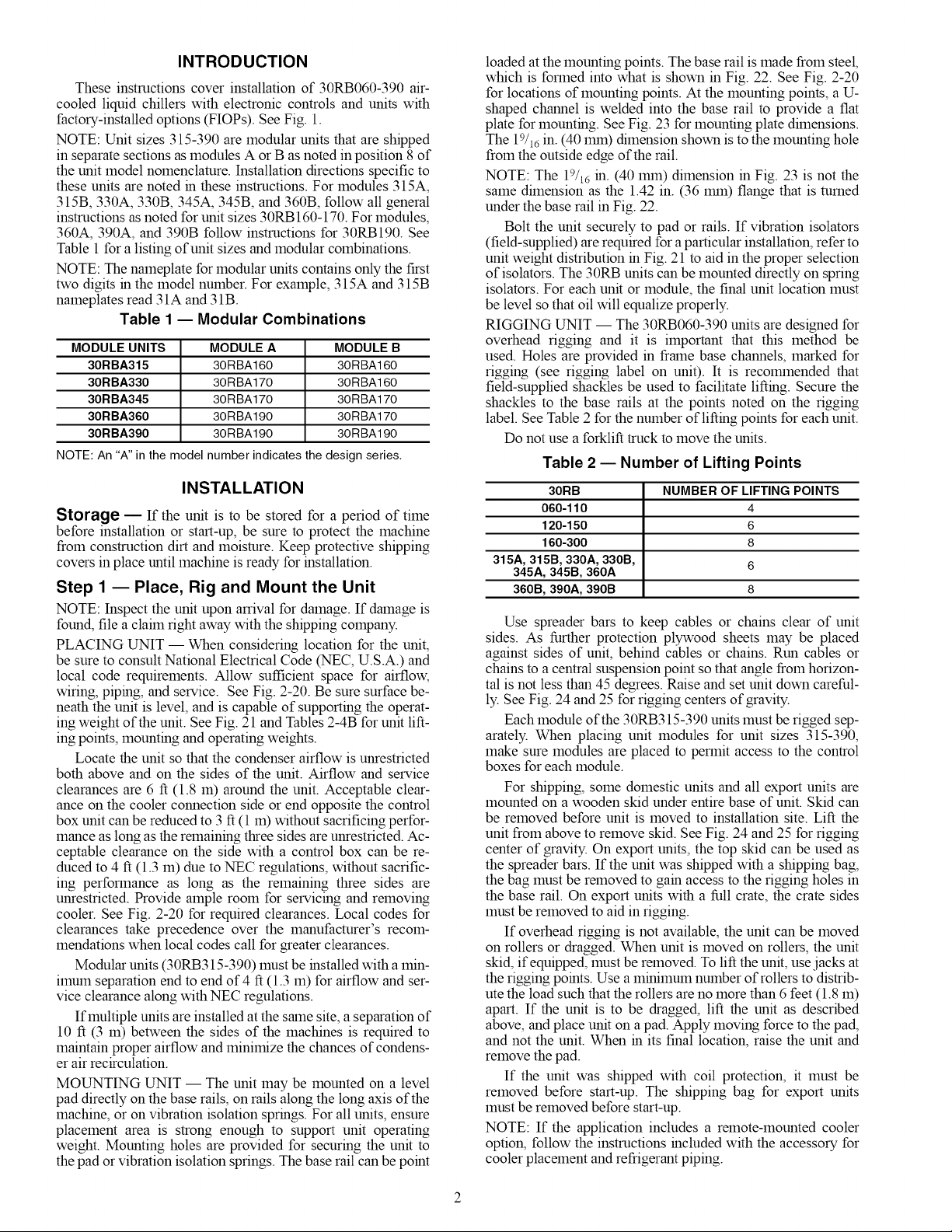
Table 1 -- Modular Combinations
MODULE UNITS MODULE A MODULE B
30RBA315 30RBA160 30RBA160
30RBA330 30RBA170 30RBA160
30RBA345 30RBA170 30RBA170
30RBA360 30RBA190 30RBA170
30RBA390 30RBA190 30RBA190
NOTE: An "A" in the model number indicates the design series,
INSTALLATION
Storage -- If the unit is to be stored for a period of time
before installation or start-up, be sure to protect the machine
from construction dirt and moisture. Keep protective shipping
covers in place until machine is ready for installation.
Step 1 E Place, Rig and Mount the Unit
NOTE: Inspect the unit upon arrival for damage. If damage is
found, file a claim right away with the shipping company.
PLACING UNIT- When considering location for the unit,
be sure to consult National Electrical Code (NEC, U.S.A.) and
local code requirements. Allow sufficient space for airflow,
wiring, piping, and service. See Fig. 2-20. Be sure surface be-
neath the unit is level, and is capable of supporting the operat-
ing weight of the unit. See Fig. 21 and Tables 2-4B for unit lift-
ing points, mounting and operating weights.
Locate the unit so that the condenser airflow is unrestricted
both above and on the sides of the unit. Airflow and service
clearances are 6 ft (1.8 m) around the unit. Acceptable clear-
ance on the cooler connection side or end opposite the control
box unit can be reduced to 3 ft (1 m) without sacrificing perfor-
mance as long as the remaining three sides are unrestricted. Ac-
ceptable clearance on the side with a control box can be re-
duced to 4 ft (1.3 m) due to NEC regulations, without sacrific-
ing performance as long as the remaining three sides are
unrestricted. Provide ample room for servicing and removing
cooler. See Fig. 2-20 for required clearances. Local codes for
clearances take precedence over the manufacturer's recom-
mendations when local codes call for greater clearances.
Modular units (30RB315-390) must be installed with a min-
imum separation end to end of 4 ft (1.3 m) for airflow and ser-
vice clearance along with NEC regulations.
If multiple units are installed at the same site, a separation of
10 ft (3 m) between the sides of the machines is required to
maintain proper airflow and minimize the chances of condens-
er air recirculation.
MOUNTING UNIT -- The unit may be mounted on a level
pad directly on the base rails, on rails along the long axis of the
machine, or on vibration isolation springs. For all units, ensure
placement area is strong enough to support unit operating
weight. Mounting holes are provided for securing the unit to
the pad or vibration isolation springs. The base rail can be point
loaded at the mounting points. The base rail is made from steel,
which is formed into what is shown in Fig. 22. See Fig. 2-20
for locations of mounting points. At the mounting points, a U-
shaped channel is welded into the base rail to provide a flat
plate for mounting. See Fig. 23 for mounting plate dimensions.
The 19/16 in. (40 lnrn) dimension shown is to the mounting hole
from the outside edge of the rail.
NOTE: The 19/16 in. (40 lnrn) dimension in Fig. 23 is not the
same dimension as the 1.42 in. (36 lnrn) flange that is turned
under the base rail in Fig. 22.
Bolt the unit securely to pad or rails. If vibration isolators
(field-supplied) are required for a particular installation, refer to
unit weight distribution in Fig. 21 to aid in the proper selection
of isolators. The 30RB units can be mounted directly on spring
isolators. For each unit or module, the final unit location must
be level so that oil will equalize properly.
RIGGING UNIT -- The 30RB060-390 units are designed for
overhead rigging and it is important that this method be
used. Holes are provided in frame base channels, marked for
rigging (see rigging label on unit). It is recolnrnended that
field-supplied shackles be used to facilitate lifting. Secure the
shackles to the base rails at the points noted on the rigging
label. See Table 2 for the number of lifting points for each unit.
Do not use a forklift truck to move the units.
Table 2 -- Number of Lifting Points
30RB NUMBER OF LIFTING POINTS
060-110 4
120-150 6
160-300 8
315A, 315B, 330A, 330B, 6
345A, 345B, 360A
360B, 390A, 390B 8
Use spreader bars to keep cables or chains clear of unit
sides. As further protection plywood sheets may be placed
against sides of unit, behind cables or chains. Run cables or
chains to a central suspension point so that angle from horizon-
tal is not less than 45 degrees. Raise and set unit down careful-
ly. See Fig. 24 and 25 for rigging centers of gravity.
Each module of the 30RB315-390 units must be rigged sep-
arately. When placing unit modules for unit sizes 315-390,
make sure modules are placed to permit access to the control
boxes for each module.
For shipping, some domestic units and all export units are
mounted on a wooden skid under entire base of unit. Skid can
be removed before unit is moved to installation site. Lift the
unit from above to remove skid. See Fig. 24 and 25 for rigging
center of gravity. On export units, the top skid can be used as
the spreader bars. If the unit was shipped with a shipping bag,
the bag must be removed to gain access to the rigging holes in
the base rail. On export units with a full crate, the crate sides
must be removed to aid in rigging.
If overhead rigging is not available, the unit can be moved
on rollers or dragged. When unit is moved on rollers, the unit
skid, if equipped, must be removed. To lift the unit, use jacks at
the rigging points. Use a minimum number of rollers to distrib-
ute the load such that the rollers are no more than 6 feet (1.8 m)
apart. If the unit is to be dragged, lift the unit as described
above, and place unit on a pad. Apply moving force to the pad,
and not the unit. When in its final location, raise the unit and
remove the pad.
If the unit was shipped with coil protection, it must be
removed before start-up. The shipping bag for export units
must be removed before start-up.
NOTE: If the application includes a remote-mounted cooler
option, follow the instructions included with the accessory for
cooler placement and refrigerant piping.
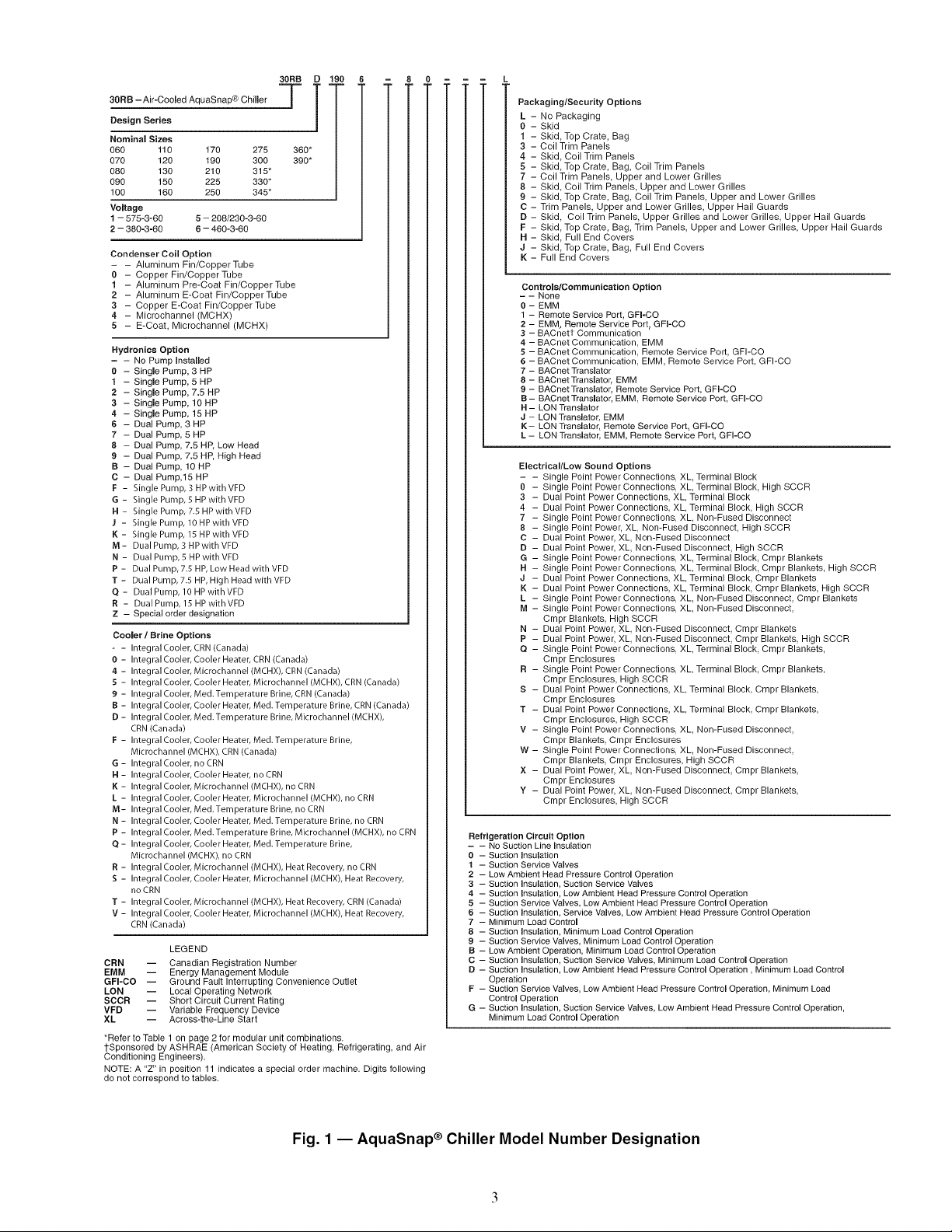
30RB - Air-Cooled AquaSnap® Chiller
Design Series
Nominal Sizes
060 110 170 275 360*
070 120 190 300 390*
080 130 210 315"
090 150 225 330*
100 160 250 345*
Voltage
1 - 575-3-60 5 - 208/230-3-60
2 - 380=3=60 6 - 460-3-60
Condenser Coil Option
- - Aluminum Fin/CopperTube
0 - Copper Fin/Copper Tube
1 - Aluminum Pre-Coat Fin/CopperTube
2 - Aluminum E-Coat Fin/CopperTube
3 - Copper E-Coat Fin/Copper Tube
4 - Microchannel (MCHX)
5 - E-Coat, Microchannel (MCHX)
Hydronioe Option
= - No Pump Installed
0 - Single Pump, 3 HP
1 - Single Pump, 5 HP
2 - Single Pump, 7.5 HP
3 - Single Pump, 10 HP
4 - Single Pump, 15 HP
6 - Dual Pump, 3 HP
7 - Dual Pump, 5 HP
8 - Dual Pump, 7.5 HP, Low Head
9 - Dual Pump, 7.5 HP, High Head
B - Dual Pump, 10 HP
C - Dual Pump,15 HP
F - Single Pump, 3 HP with VFD
G - Single Pump, 5 HP with VFD
H - Single Pump, 7.5 HPwithVFD
J - Single Pump, 10 HP with VFD
I{ - Single Pump, 15 HP with VFD
M - Dual Pump, 3 HP with VFD
N - Dual Pump, 5 HPwithVFD
P - Dual Pump, 7.5 HP, Low Head with VFD
T - Dual Pump, 7.5 HP, High Head with VFD
Q - Dual Pump, 10 HP with VFD
R - Dual Pump, 15 HPwith VFD
Z - Special order designation
Cooler / Brine Options
- - Integral Cooler, CRN (Canada)
0 - Integral Cooler, Cooler Heater, CRN (Canada)
4 - Integral Cooler, Micrechannel (MCHX), CRN (Canada)
5 - Integral Cooler, Cooler Heater, Microchannel (MCHX), CRN (Canada)
£ - IntegralCooler, Med.Temperature Brine, CRN (Canada)
B - Integral Cooler, Cooler Heater, Med. Temperature Brine, CRN(Canada)
D-Integ ral Cooler, Meal. Temperatu re Brine, Microchannel (MCHX),
CRN (Canada)
F - Integral Cooler, Cooler Heater, Med. Temperature Brine,
Micrechannel (MCHX), CRN (Canada)
G - Integral Cooler, no CRN
H - Integral Cooler, Cooler Heater, no CRN
K - Integral Cooler, Micrechannel (MCHX), no CRN
L - Integral Cooler, Cooler Heater, Microchannel (MCHX), no CRN
M- Integral Cooler, Med. Temperatu re Brine, no CRN
N - Integral Cooler, Cooler Heater, Med. Temperature Brine, no CRN
P- IntegralCooler, Med.Temperature Brine, Microchannel(MCHX),no CRN
Q - Integral Cooler, Cooler Heater, Med. Temperature Brine,
Micrechannel (MCHX), no CRN
R - Integral Cooler, Micrechannel (MCHX), Heat Recovery, no CRN
S - Integral Cooler, Cooler Heater, Microchannel (MCHX), Heat Recovery,
no CRN
T - Integral Cooler, Micrechannel (MCHX), Heat Recovery, CRN (Canada)
V - Integral Cooler, Cooler Heater, Microchannel (MCHX), Heat Recovery,
CRN (Canada)
LEGEND
CRN -- Canadian Registration Number
EMM -- Energy Management Module
GFI-CO -- Ground Fault Interrupting Convenience Outlet
LON -- Local Operating Network
SCCR -- Short Circuit Current Hating
VFD -- Variable Frequency Device
XL -- Across-the-Line Start
*Refer to Table 1 on page 2 for modular unit combinations
1-Sponsored by ASHRAE (American Society of Heating, Refrigerating, and Air
Conditioning Engineers).
NOTE: A "Z" in position 11 indicates a special order machine. Digits following
do not correspond to tables.
PackaginglSecurity Options
L - No Packaging
O - Skid
1 - Skid, Top Crate, Bag
3 - Coil Trim Panels
4 - Skid, Coil Trim Panels
5 - Skid, Top Crate, Bag, Coil Trim Panels
7 - Coil Trim Panels, Upper and Lower Grilles
8 - Skid, Coil Trim Panels, Upper and Lower Grilles
9 - Skid, Top Crate, Bag, Coil Trim Panels, Upper and Lower Grilles
C - Trim Panels, Upper and Lower Grilles, Upper Hail Guards
D - Skid, Coil Trim Panels, Upper Grilles and Lower Grilles, Upper Hail Guards
F - Skid, Top Crate, Bag, Trim Panels, Upper and Lower Grilles, Upper Hail Guards
H - Skid, Full End Covers
J - Skid, Top Crate, Bag, Full End Covers
K - Full End Covers
Controls/Communication Option
- - None
0 - EMM
1 - Remote Service Port, GFI-OO
2 - EMM, Remote Service Port, GFI-CO
3 - BACnett Communication
4 - BACnet Communication, EMM
5 - BACnet Communication, Remote Service Port, GFI-CO
6 - BACnet Communication, EMM, Remote Service Port, GFI-CO
7 - BACnet Translator
8 - BACnet Translator, EMM
9 - BACnet Translator, Remote Service Port, GFI-CO
B- BACnet Translator, EMM, Remote Service Port, GFI-CO
H - LON Translator
J - LON Translator, EMM
K- LON Translator, Remote Service Port, GFI-CO
L - LON Translator, EMM, Remote Service Port, GFI=CO
Electrical/Low Sound Options
- - Single Point Power Connections_ XL, Terminal Block
O - Single Point Power Connections_ XL, Terminal Block_ High SCCR
3 - Dual Point Power Connections_ XL, Terminal Block
4 - Dual Point Power Connections_ XL, Terminal Block, High SCCR
7 - Single Point Power Cennections_ XL, Non-Fused Disconnect
8 - Single Point Power, XL_ Non-Fused DisconnecL High SCCR
C - Dual Point Power, XL_ Non-Fused Disconnect
D - Dual Point Power, XL, Non-Fused DisconnecL High SCCR
G - Single Point Power Connections_ XL Terminal Block_ Cmpr Blankets
H - Single Point Power Connections_ XL Terminal Block_ Cmpr Blankets, High SCCR
J - Dual Point Power Connections_ XL Terminal Block, Cmpr Blankets
K - Dual Point Power Connections_ XL Terminal Block, Cmpr Blankets, High SCCR
L - Single Point Power Connections, XL Non-Fused Disconnect, Cmpr Blankets
M - Single Point Power Connections, XL Non-Fused Disconnect,
Cmpr Blankets, High SCCR
N - Dual Point Power, XL, Non-Fused Disconnect, Cmpr Blankets
P - Dual Point Power, XL, Non-Fused Disconnect, Cmpr Blankets, High SCCR
Q - Single Point Power Connections, XL, Terminal Block, Cmpr Blankets,
Cmpr Enclosures
R - Single Point Power Connections, XL, Terminal Block, Cmpr Blankets,
Cmpr Enclosures, High SCCR
S - Dual Point Power Connections, XL, Terminal Block, Cmpr Blankets,
Cmpr Enclosures
T - Dual Point Power Connections, XL, Terminal Block, Cmpr Blankets,
Cmpr Enclosures, High SCCR
V - Single Point Power Connections, XL, Non-Fused Disconnect,
Cmpr Blankets, Cmpr Enclosures
W - Single Point Power Connections, XL, Non-Fused Disconnect,
Cmpr Blankets, Cmpr Enclosures, High SCCR
X - Dual Point Power, XL, Non-Fused Disconnect, Cmpr Blankets,
Cmpr Enclosures
Y - Dual Point Power, XL, Non-Fused Disconnect, Cmpr Blankets,
Cmpr Enclosures, High SCCR
Refrigeration Circuit Option
- - No Suction Line insulation
0 - Suction Insulation
t - Suction Service Valves
2 - Low Ambient Head Pressure Control Operation
3 - Suction Insulation, Suction Service Valves
4 - Suction Insulation, Low Ambient Head Pressure Control Operation
5 - Suction Service Valves, Low Ambient Head Pressure Control Operation
6 - Suction Insulation, Service Valves, Low Ambient Head Pressure Control Operation
7 - Minimum Load Control
8 - Suction Insulation, Minimum Load Control Operation
9 - Suction Service Valves, Minimum Load Control Operation
B - Low Ambient Operation, Minimum Load Control Operation
C - Suction Insulation, Suction Service Valves, Minimum Load Control Operation
D - Suction insulation, Low Ambient Head Pressure Control Operation, Minimum Load Control
Operation
F - Suction Service Valves, Low Ambient Head Pressure Control Operation, Minimum Load
Control Operation
G - Suction Insulation, Suction Service Valves, Low Ambient Head Pressure Control Operation,
Minimum Load Control Operation
Fig. 1 -- AquaSnap ® Chiller Model Number Designation
4:_
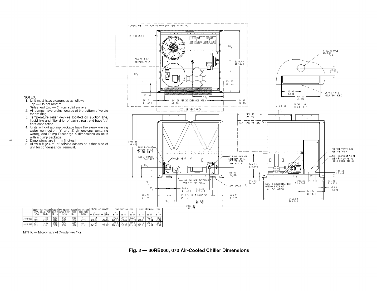
NOTES:
1.
2.
3.
4.
L
Unit must have clearances as follows:
Top -- Do not restrict.
Sides and End -- 6' from solid surface.
All pumps have drains located at the bottom of volute
for draining.
Temperature relief devices located on suction line,
liquid line and filter drier of each circuit and have 114"
flare connection.
Units without a pump package have the same leaving
water connection, Y and Z dimensions (entering
water), and Pump Discharge X dimensions as units
with a pump package.
Dimensions are in mm [inches].
Allow 8 ft (2.4 m) of service access on either side of
unit for condenser coil removal.
5. 228137
6. [8982]
"l ....r
1447 81570] _ _ " C_{'Tj_F '
.............4_ __Y---: -- _ J
COOLEDT8RE UIII_ IIIi_
8ERVIGEAREA:IlIL:_--_',_ _11# _!o_
p_ _ _///////////////_Sf/JA
281[ 06103 _ i_18_ PIPING ENTRANCE AREA' "F ",
[ C?IL SERVICE. ARE_.......... I
4' VICTAULIC
PDX
40889
116i0]
41447
[1682]
I--D43848--1
[96 00]
COIL SERVICE AREA
i
ENTERING WATER
860 93
89]
,801
21573
[840]
DETAIL A
408 89
[6 O]
DIGGING HOLE
¢3800
- [1501
,L,oooo_i ) t
LRLRL80000 l _''%_F_0%LE
1787]
AIR FLOW
DETAIL A
SCALE 1:2
[
J_ : qH_
I RAChel ¢O_4MUNICATIONS [9 70]
OPTION KNOCKOUT I
FOR 1/2" CONDUIT
k--
94914 --
[37 371
2159 89
[88 04]
ONTROLIPOWED
_ALL VOLTAGES BOX
718' KNOCKOUTTO BE
_--USED FOR LOCATING
FIELD POWER WIRING
19000
1748]
33650
[1825]
8809
[1,50]
WEIGHT MAX WEIGHT IEIGHl MAX WEIGHT WEIGH1 _AX WEIGHT CERTER OF GRAVITY PU_P SUCTION (P8) PUMP DISCHAR6E (PD)
CUIAL CUIAL PU_P CUICU CUICU PUMP MCHX MCHX P_M9 CGx COy X25 vIb/k9 Ib/k9 Ibft9 Ib/k9 Ib/t9 Ib/k9 _M lINCH] _M lINCH] ::H25 :9=!25 :9=X25 ::1:_25 ±!25
41!1 4944 4595 5426 9788 4616 1!04 1098 6756 3099 9581 9810 4826 1880
9088-060 1869 2247 2088 2466 _716 2094 [4582] [4086] [26 6] [122] [139] [150] [190] [74]
4917 5150 4799 5632 3978 4811 1165 1013 6758 3899 9581 3810 4826 1880
9ORS-OHO 1992 2641 2181 2560 1804 2182 [4586] [3988] [266] [122] [1_9] [150] [190] [74]
[94221
MCHX -- Microchannel Condenser Coil
Fig. 2 -- 30RB060H 070 Air-Cooled Chiller Dimensions
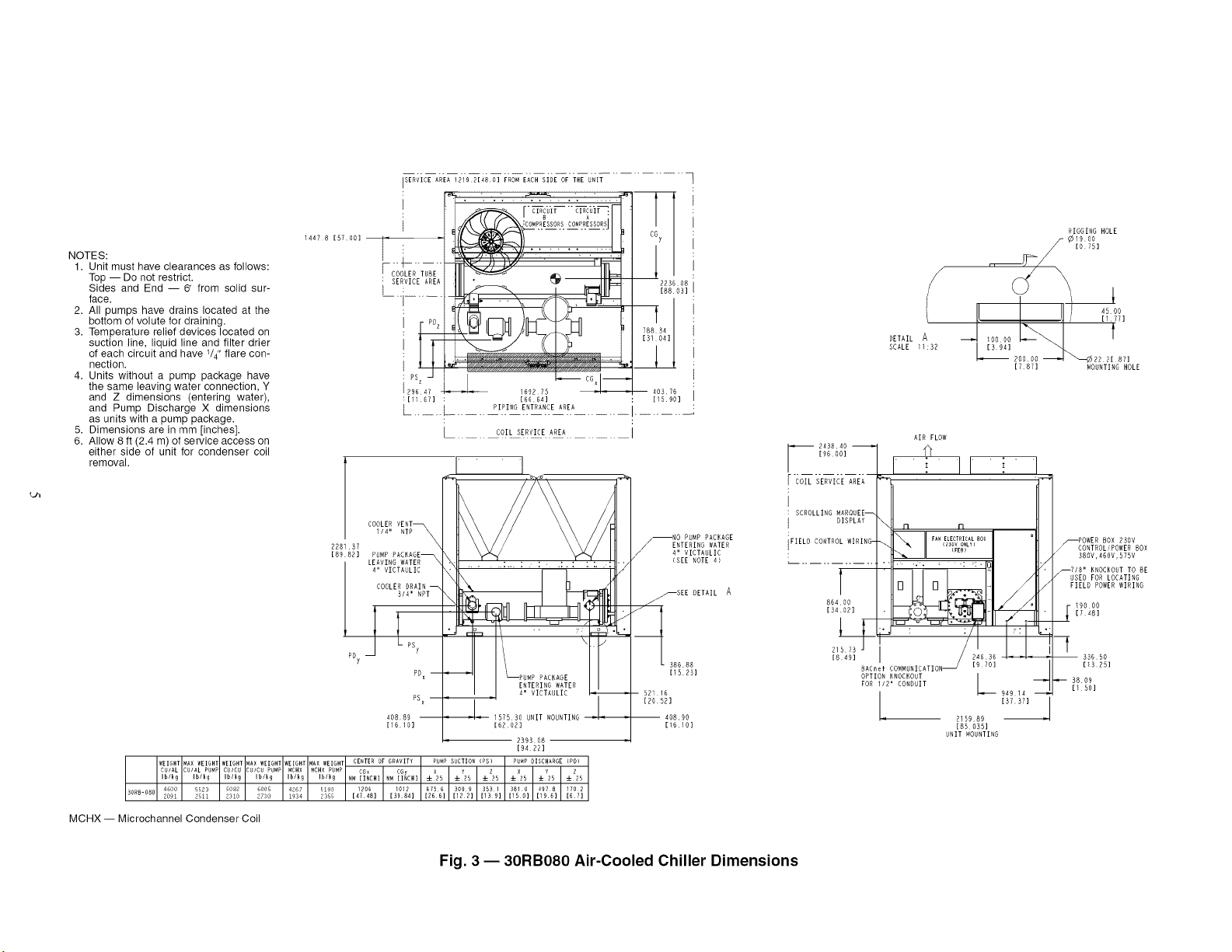
NOTES:
1. Unit must have clearances as follows:
Top -- Do not restrict.
Sides and End -- 6' from solid sur-
face.
2. All pumps have drains located at the
bottom of volute for draining.
3. Temperature relief devices located on
suction line, liquid line and filter drier
of each circuit and have 1/4" flare con-
nection.
4. Units without a pump package have
the same leaving water connection, Y
and Z dimensions (entering water),
and Pump Discharge X dimensions
as units with a pump package.
5. Dimensions are in mm [inches].
6. Allow 8 ft (2.4 m) of service access on
either side of unit for condenser coil
removal.
14478 [5700]
228187
[8982]
ISERVICE AREA 121921480] FROM EACH SIDE OF THE UNIT
I
I
F OOLER'FTU
' SERVICE AREA
I__i.....
I
: PSz -
29047
:[1107]
L ....
J/x_\L.fFA_u__ CONtRT'Rottll
[66 64]
PIPING ENTRANCE AREA
COIL SERVICE AREA
COOLER VENT
1/4" NTP_
PUMP
4" VICTAULIC
WEIGHT MAX WEIGHT WEIGH1 _AX WEIGHT WEIGHI _AX WEIGHT
CU/AL CUfAL PUMP CU/CU ;UfCU PUMP MCHX MCHX PUMP
Ib/k_ Ib/I g Ib/I 9 Ib/k 9 Ib/k 9 Ib/k_
3ONB-OHO 4600 5523 5082 6005 4267 5190
2091 2511 2310 2730 1934 2355
MCHX -- Microchannel Condenser Coil
[1610]
[9422]
CENTER OF GRAVITY PUMP SUCTION (PS) PUMP OISCBARGE [PD)
CGx CGp
T
CGy
223608
[8803]
78834
[}_ 04]
40876
[15901
NO PUMP PACKAGE
ENTERING WATER
_4" VICTAULIC
<SEE NOTE 4)
_SEE OETAIL A
38688
[1523]
[20521
[1610]
/
DETAIL A
SCALE 11:32
RIGGING HOLE
[0751
20_2221871
[787] MOUNTING HOLE
243840
[9600]
COIL SERVICE AREA
SCROLLING IARQUEE_
_ISPLAY
FIELD CONTROL WIRING-
AIR FLOW
¢
_ n n
FANELECTRICALBOX
(230VONLY)
(FEB)
/
[8491 670 ] , ,
BACneI COMMUNICATION _
OPTION KNOCKOUT L
FOR 1/2' CONDUIT _
94914
• [57 37]
215989
[85 035]
UNIT _40UNTI NG
POWERBOX 290V
_CONTROL/POWER BOX
380V,460V,GTGV
_7/8" KNOCKOUT TO HE
USED FOR LOCATING
FIELD POWER WIRING
- 90 00
[748]
33650
[1328]
9809
11 50]
Fig. 3 -- 30RB080 Air-Cooled Chiller Dimensions
Q'h
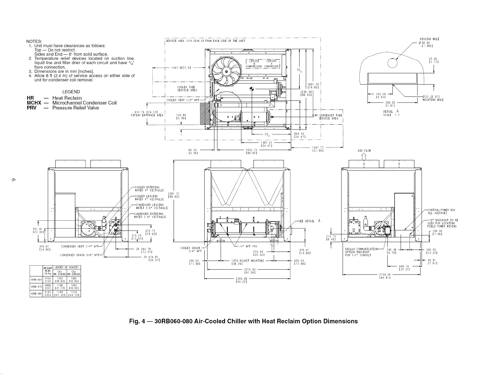
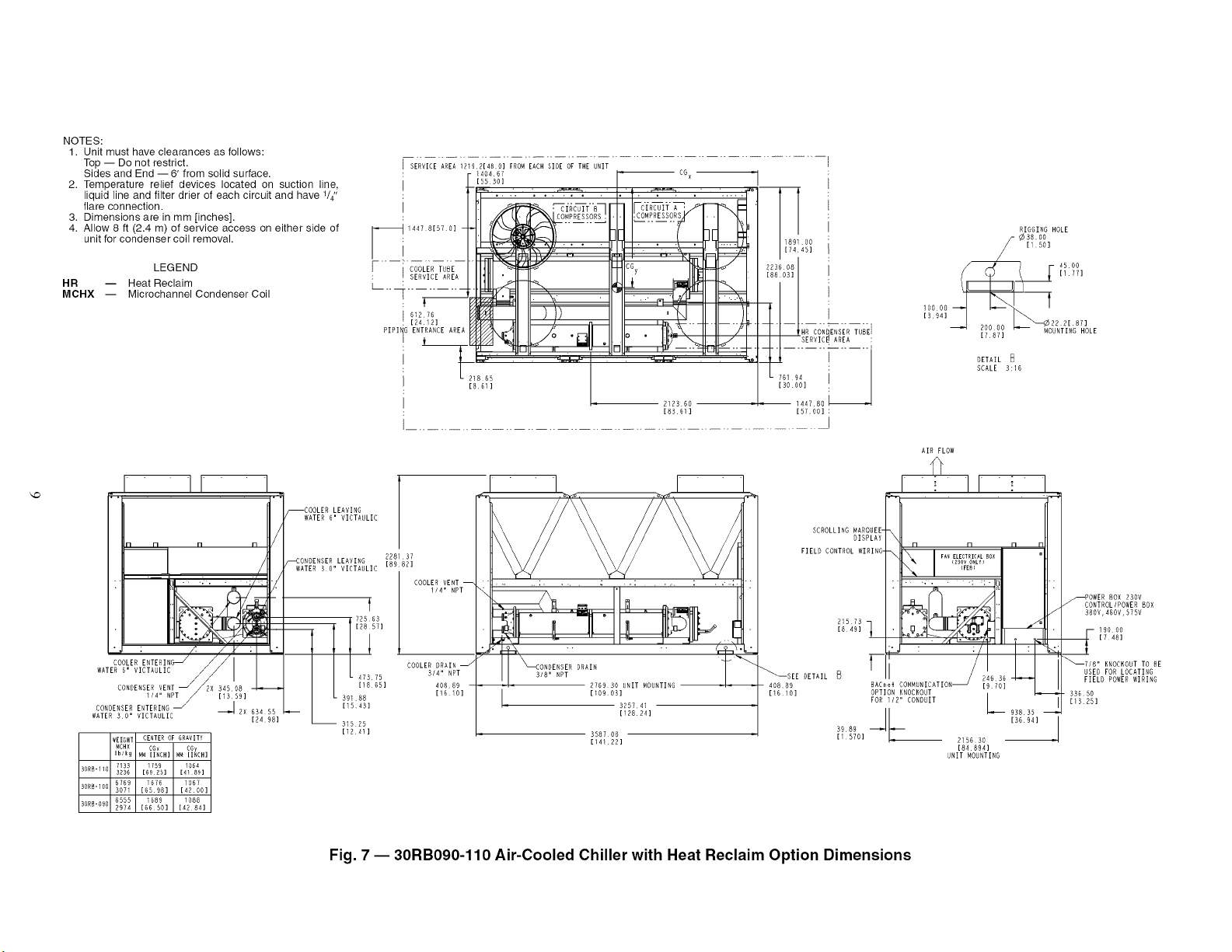
NOTES:
1. Unit must have clearances as follows:
Top -- Do not restrict.
Sides and End -- 6' from solid surface.
2. Temperature relief devices located on suction line,
liquid line and filter drier of each circuit and have 1/4"
flare connection.
3. Dimensions are in mm [inches].
4. Allow 8 ft (2.4 m) of service access on either side of
unit for condenser coil removal.
LEGEND
HR -- Heat Reclaim
MCHX -- Microchannel Condenser Coil
PRV -- Pressure Relief Valve
SERVICEAREA_2192148G]FRoMiACHS_OiSrT_&Z
_- 1447 81570]
; COOLER TUBE
I SERVICE AREA
r
612 16 [2412] i
PIPING ENTRANCE AREA : 12680
[499]
t
I
8533
[3361
I I I 1
'_--_1 _'_ "--COOLER ENTERING
WATER 4" VICTAULIC
228 37
--COOLER LEAVING 189 82]
WATER 4 I VICTAULIC
-_ONDERSER LEAVING
_.ql'" . ; _ WATER 30" VICTADLIC
_- _,_* _'_I " I --CONDENSER ENTERING
WATER 3 0 I VICTAULIC
f :
5 '9'l 1
i • -, _, , 47375
[23 30]
25 [181651
Z/I I_1 ['2,411 ,
37601 CONDENSER VENT 1/4' RPT CO0 R
[13571 3/4" NPT
CONDENSER DRAIN ' 2 2X 67481
[26 57] 45663
[17 98]
WEIGHT CENTER OF GRAVITY
_CHX CGx CGy
Iblk9 _M lINCH] M_ lINCH]
4703 235 1082
HORB-060 2133 [40 62] [4H HO]
30R_.O10 4898 198 1093
2221 [4! 17] [43 03]
30RlJ-080 587 199 1120
2353 [4720] [_410]
2052,75
[8082]
[94.22]
138721
154611
CG7
I 1891 29
t
[74 46] '
' H _!!_ES EAHR!_8E
2236 08
[88 03] i
k_I[ IIII_ I
_ -- 144777 _]
[57 OO]
_SEE DETAIL A
37601
11480]
45663
RIGGING HOLE
--¢ 3809
114961
J
_ 2OO OO J WOUNTING HOLE
[787]
DETAILA
SCALE 1:2
I
21573
[849]
t
AIR FLOW
I E I I " 1
_'_//' I I".L_
"_OR[1 /2ll c_NOUIT 2154[/ _J_ZHJ]
[848]
/-_ONTROL/POWER 80X
ALL VOLTAGES
_718" RNOCROUT TO BE
USED FOR LOCATING
FIELD POWER WIRING
_[ 9000
[748]
33650
[1325]
4091
[1 61]
Fig. 4 -- 30RB060-080 Air-Cooled Chiller with Heat Reclaim Option Dimensions
--4
SERVICE AREA 1219 2148 O] FROM EACH SIDE OF THE UNIT
: _-- ----
"T
1017 46
[40 06]
CG x
e
, CGy
.... i 223608
i _ i_ I 188031
78835
3104]
163207 7 55
164251 [5691]
PIPING ENTRANCE AREA
[787]
228137
[89821
PUMP PACKA(
LEAVING WATER
COOLER
3/4" NPT
40889
[1610]
PACKAGE
ENTERING WATER
_" VICTAULIC
276930
t [109031 L_
UNIT MOUNTING
PD× 29220 99244
[39071
pS x [11 501
219510
[86421
358708
[14i221
SCROLLING MAROUEE--
DISPLAY
FIELD CONTROL WIRING
PUMP PACKAGE
ENTERING WATER
4" VICTAULIC T
(SEE NOTE 4)
86400
[3402]
39188 ___
[1543]
_SEE DETAIL
DETAIL _ RIGGING HOLE
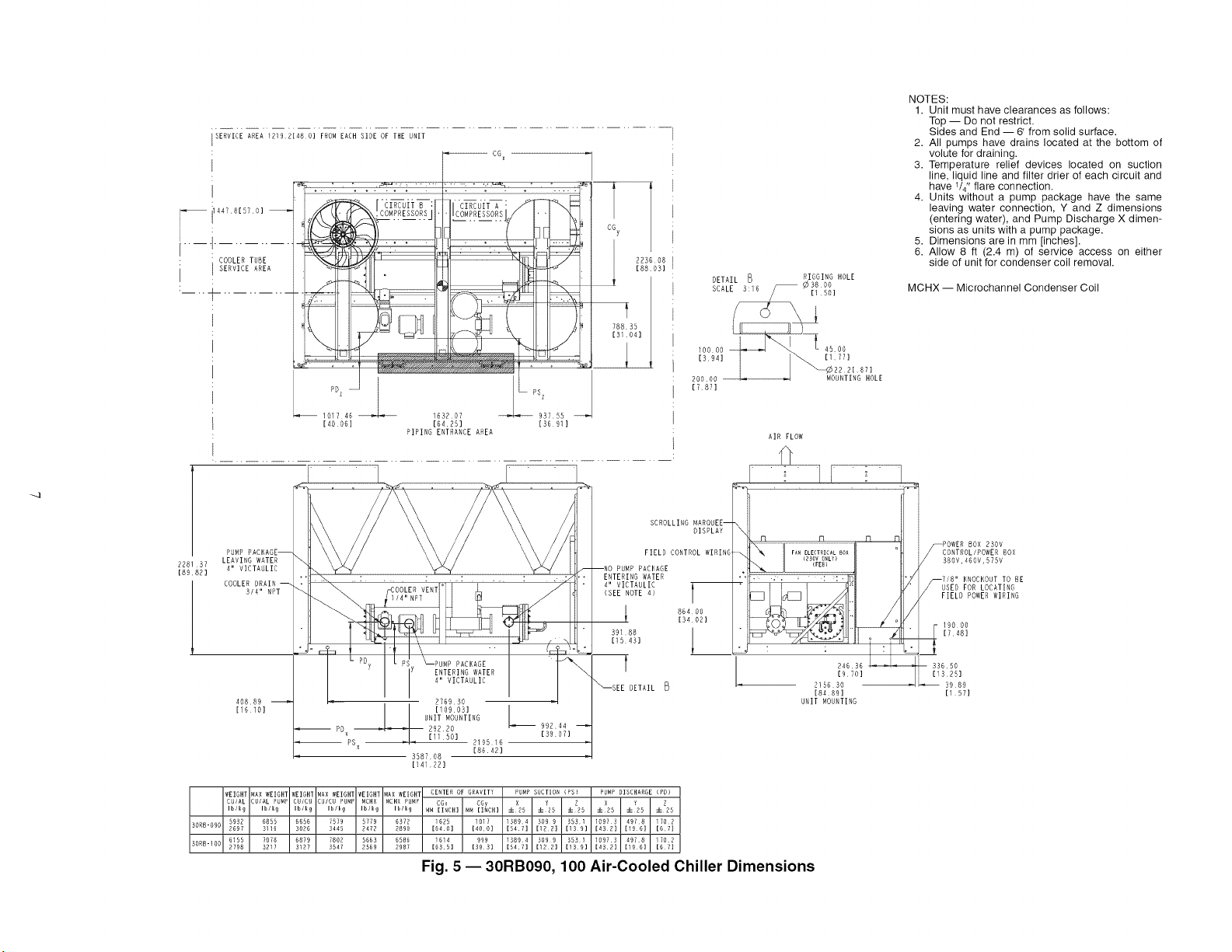
NOTES:
1. Unit must have clearances as follows:
Top -- Do not restrict.
Sides and End -- 6' from solid surface.
2. All pumps have drains located at the bottom of
volute for draining.
3. Temperature relief devices located on suction
line, liquid line and filter drier of each circuit and
have 1/4" flare connection.
4. Units without a pump package have the same
leaving water connection, Y and Z dimensions
(entering water), and Pump Discharge X dimen-
sions as units with a pump package.
5. Dimensions are in mm [inches].
6. Allow 8 ft (2.4 m) of service access on either
side of unit for condenser coil removal.
MCHX -- Microchannel Condenser Coil
AIR FLOW
fl
; II "
#
_ F! O _ _ 43 FPOWEH BOX 230V
k\ II I
380V,460V,575V
\_., II < .... !! / / CONTROL/POWER
FIELD POWERWIRING
, _ 19000
[7481
24636 _i ' -- 33650
[970] [1325]
215630 _ 3989
[8489] [157]
UNIT MOUNTING
WEIGHT MAX WEIGH1 WEIGHT MAX WEIGHT WEIGHT _AX WEIGHT CENTER OF GRAVITY PUMP SUCTION (PSI
CUIAL CU/AL PHMF CUICN CU/CU PUMP MCHX MCHX PUMP CGx CGy Y !Ib/kR Ib/kg IDleR Ib/kg Ib/k9 Ib/k9 MM lINCH[ MM lINCH[ ±X25 ±25 • 25
30R8-090 5992 6855 6656 7579 5779 6572 1625 1017 13894 3099 9551
2697 3116 3096 3445 2472 2890 [640] [4OO] [547] [199] [19 9]
5ORH-]OO 6155 7078 6879 7809 5663 6586 i614 999 13894 309 9 353 1
2798 5217 3127 3547 2569 2987 [635] [993] [547] [122] [159]
PUMP DISCHARGE (PD}
i X25 ±Y25 ±Z25
1097 9 497¸8 _702
[43 R] [19 0] [67]
I097¸3 497¸8 170¸2
[432[ [INOI [6¸7[
Fig. 5 --30RB090, 100 Air-Cooled Chiller Dimensions
Go
_ iA4781570]
COOLER TUBE
SERVICE AREA
LL_
PDz PS z
SERVICE AREA i219 2148 O] FROM EACH SIDE OF THE UNIT
CG X
...<-_j,
22484 -
[885]
"1
rOe ¸
- ]-¢i_ _
_OR_.
e__, _/////////__///,/////J//////_//_ ,_le
- - - 244609 - - 916,15 -
196301 136,071
PIPING ENTRANCE AREA
I
COIL SERVICE AREA
]
COOLER VENT
228137 1/4" NPT
[8982]
PUMP
COOLER ORAIN
3/4" NPT pD x
40889
[1610]
6" VICTAULIC
51582 SEE DETAIL
I [20311
. 276930 UNIT MOUNTING
[I09031
PSx 2728,56
[10742]
9587 08
[i41,22]
l
CGy
2236
[88
t
76194
[30OO]
RIGGING HOLE
¢3800
[150]
17871
DETAIL
SCALE 3:16
AIR FLOW
fl
[-_ 2438 40
196o01 ' ' : ' ' ' : "
COIL S-ERDICE AREA _ [_
H
I SCROLLING MARQUEE- _ [I
i DISPLAY n n Iq IqJl
,FIELD CONTROL WIRING-_, _'_ i FAN(E2L_EoCvTRoI_LAyL)BOX "tl /
,RUMR,ACKAO ...." ' : ::; /f(:
ENTERINGWATER I I n n // / ii /
6" VICTAULIC ' I u _>\I _3;_"_7"_ / II/
<SEE NOTE 4) 860.8' I I _-'_i r,_'J_t,-(_{--_'kl / I)_
- _9188 21_73/ / I I -
[ls:43] [8491 / 2A6: ,. :!. :
" ' / [9 70]
RAChel COMMUNICATION_ I
OPTION KNOCKOUT I
408.89 FOR /2" CONDUIT
[16.i0] _ 93835
[36 94]
I 215630
[84 89]
UNIT MOUNTING
WEIGHT MAX WEIGHT WEIGHT 4AX WEIGHT WEIGHT _AX WEIGHT CENTER OF GRAVITY PUMP SUCTION (PS) PUMP DISCHARGE (PD)
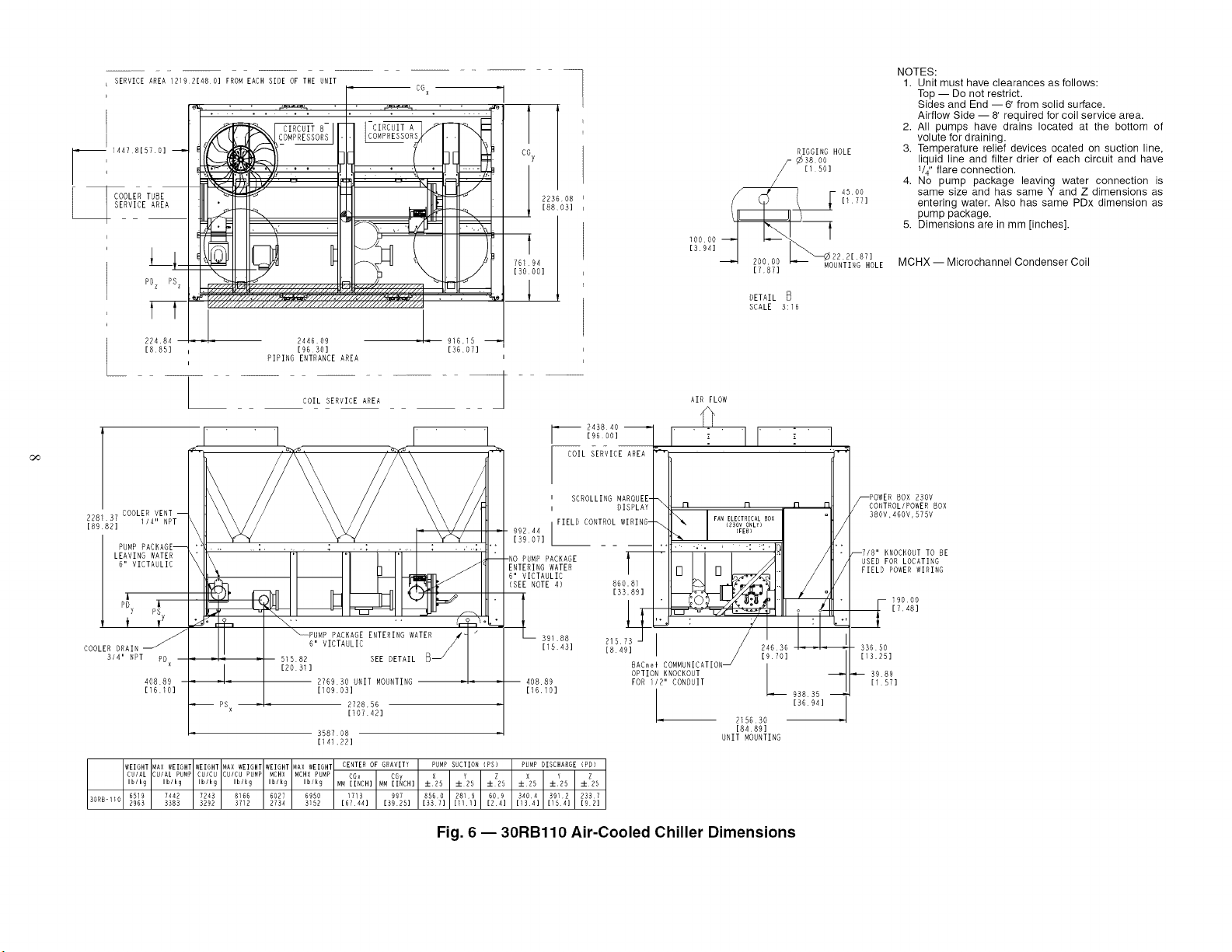
CUIAL CUIAL PUMP CUICU :UICU PU_P MCHX NCHX PUMP CGx CG 7 [I11] [134]Ib/k9 Ib/k9 Ib/k9 Ib/k9 Ib/k9 Ib/k9 MM[67[INCH]44] HM[3925][INCH] ±X25 4-!25 4-! 25 4-!25 4-Y25 4-!2530RR-110 6519 7442 7243 8166 6027 6950 1713 997 8560 2819 60.9 3404 9912 2337
2963 3383 3292 3712 2734 3162 [337] [R4] [164] [92]
Fig. 6 --30RB110 Air-Cooled Chiller Dimensions
NOTES:
1. Unit must have clearances as follows:
Top -- Do not restrict.
Sides and End --6' from solid surface.
Airflow Side -- 8' required for coil service area.
2. All pumps have drains located at the bottom of
volute for draining.
3. Temperature relief devices ocated on suction line,
liquid line and filter drier of each circuit and have
V4" flare connection.
4. No pump package leaving water connection is
same size and has same Y and Z dimensions as
entering water. Also has same PDx dimension as
pump package.
5. Dimensions are in mm [inches].
MCHX -- Microchannel Condenser Coil
POWER BOX 230V
CONTROL/POWER BOX
380V,460V,S75V
_718" KNOCKOUT TO BE
USED FOR LOCATING
FIELD POWER WIRING
r- 19000
[748]
33650
[i3.25]
-- 3989
[1.571
NOTES:
1. Unit must have clearances as follows:
Top -- Do not restrict.
Sides and End -- 6' from solid surface.
2. Temperature relief devices located on suction line,
liquid line and filter drier of each circuit and have 1/4"
flare connection.
3. Dimensions are in mm [inches].
4. Allow 8 ft (2.4 m) of service access on either side of
unit for condenser coil removal.
LEGEND
HR -- Heat Reclaim
MCHX -- Microchannel Condenser Coil
_D
COOLER
EONOENGERENJN:"L/
WEIGHT CENTER OF GRAVITY
MCH× CGx C5
Ib/kg MM _CH M_ _CH
BORR-HC 7133 1759 1064
3256 [6955] [41HP]
3HRK-IOC 6769 i576 1067
3071 [5598] [4200]
30RH-OPC 6555 i689 1088
29YA [5650] [A28A]
[i3 59]
WATER 30" VICTAULIC
f
SERVICE AREA 1R19 R[48 O] FROM EACH SIDE OF THE UNIT
--1[;!43_; . , ,
-- 1.1 -__cG,
A47,[STDI
!t_:_, _ ))) II II ,Yq II II )
PIPIIG ENTRANCE ARE ___j_ E o__ [] __
I 212360
: [83 61 ]
......................
"1
T
[88 03] /
223608
SERVICEAREAi i
=e ........ T ..... i
144780 L_
[57 OO] :
I
RIGGING HOLE
_/¢SHDD
[150 1
' 4500
[177]
[3941
T_LE
[78Tl
DETAIL
SCALE 3:15
[8982]
H8 55]
[1610]
39_88
[1241]
I, [lORD3]
325741
[12824]
3587 08
114122[
AIR FLOW
.q
SCROLLING _ARQUEE- __
DISPLAY n n
FIELD CONTROL WIPING- IFA_'_EpI'KEoCvTRoINCZ_YL}BOX
II\ i .....
:.. ... , .: ::.!?
215 73 "
[849] 1
II • Z_
DETAIL _ F _'] : )/246[
_0889 8ACrei COMMUNICATION_ [9 70]
[15 1O] OPTION KNOCKOUT
FOR /2" CONDUIT
3989 Jl_
[15701
L
J
L 93835 _
[35941
215530
[8_894]
UNIT #OUNTING
POWER BOX 230V
//_CONTROLIPOWER 80X
380V,46OV,S75V
19000
[748]
_7/8" KNOCKOUTTO 8E
USED FOR LOCATING
FIELD POWER WIRING
33550
[1325]
Fig. 7- 30RB090-110 Air-Cooled Chiller with Heat Reclaim Option Dimensions
SERVICE AREA 121921480] FROM EACH SIDE OF THE UNIT
-- CTSA x
COOLER TUNE
RVICE AREA
l l
PDz PBz
! f
[
F CG X
188 03]
I4R$o, _gN_ol INN03,
_IRIRGENTRANCERREA
COILGENVICEAREA
COOLER VENT_
I/4" NTP
RUMP
LEAVING WATER
228137 N" VICTAULIC
[8982]
PUMP PACKAGE
ENTERING WATER
_SEE DETAIL
[1610]
COOLER DRAIN
314" NPT
198165
[7802]
_Ro:ILc??:ING
PN× 44092 ENTERING WATER [4563]
[17361 6" VICTAULIC
2970.06
[H6 99]
478]08
[18823]
WEIGHT 4AX WEIGH1 WEIGHT MAX WEIGHT WEIGHT 4AX WEINHI CENTER OF GRAVITY PUMP SUCTION (PS)
CU/AL ]U/AL PUMF CU/CU CUICU PUMP _CHX MCBX PUMP CGx COy X Y Z
Ib/_g Ib/kg IbiS9 Ib/kg Ib/kR Ib/kR M_ :INCH] _M :INCH: /=25 /:25 /=25
7990 8615 8594 9457 7119 8042 2846 993 18085 2819 609
30RB-12C 3488 9907 5871 4290 3229 3948 [9296] [5909] [712] [1!1] [24]
30RR-15C 8045 8958 9010 9953 7402 8825 2272 988 ]8085 2819 609
3649 4068 4087 4500 3358 3776 [8945] [5870] [712] [111] [24]
PUHP DISCHARGE _PU) COOLER TUNE
_ERVICE AREA
Y
/=XR5 /=95 /=!25 CTNA x
MM :INCH]
1866_ 5912 2837 1447 8
[598] [154: [92] [570]
1386_ 5912 2337 1447B
[538] [_541 [92] [570]
[1610]
39188
[i543]
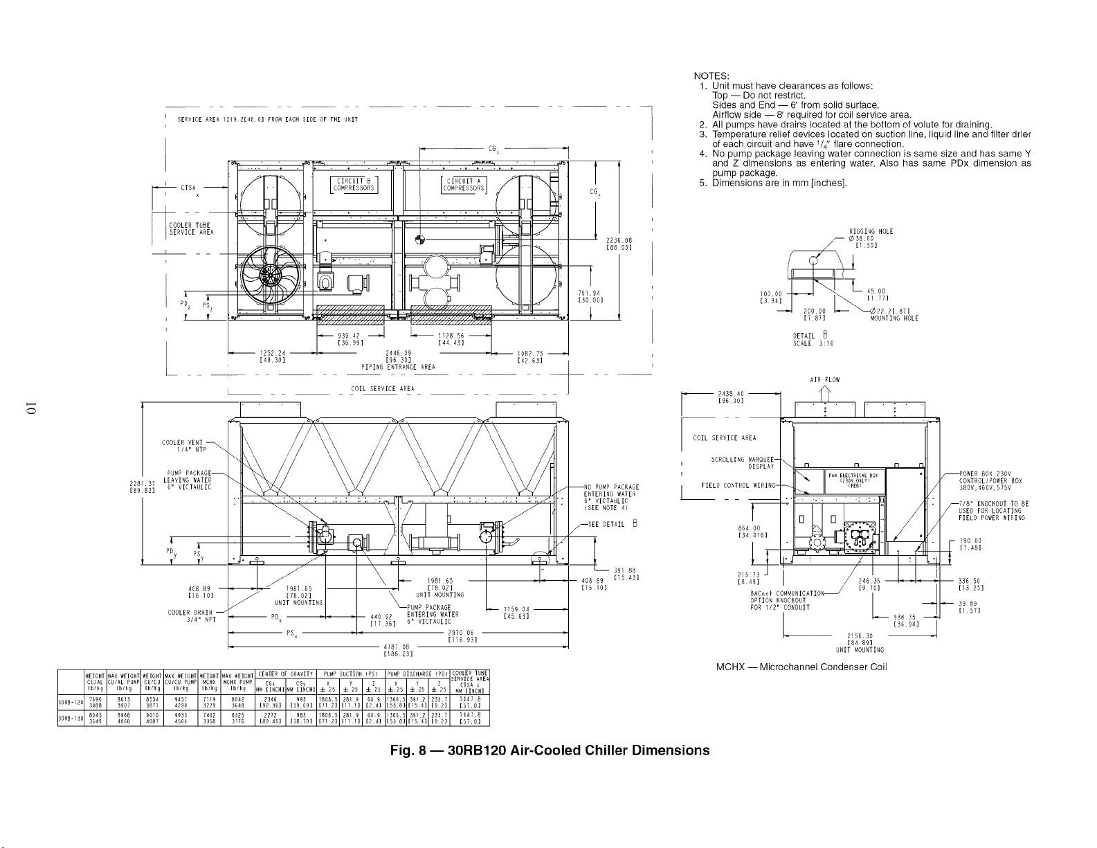
NOTES:
1. Unit must have clearances as follows:
Top -- Do not restrict.
Sides and End -- 6' from solid surface.
Airflow side -- 8' required for coil service area.
2. All pumps have drains located at the bottom of volute for draining.
3. Temperature relief devices located on suction line, liquid line and filter drier
of each circuit and have 1/4" flare connection.
4. No pump package leaving water connection is same size and has same Y
and Z dimensions as entering water. Also has same PDx dimension as
pump package.
5. Dimensions are in mm [inches].
RIGGING HOLE
(
R000N NI8.
.871 ,O NTIN8ROLE
DETAIL
SCALE 3;16
AIR FLOW
_ 243840IgDool I fl
_ I1
COIL SERVICE AREA
SCROLLING HANOUEE--
: DISPLAY _ n
FIELD CONTROL WIRING- __
B64_
215 73 J / I
COMHURICATION_ [9 701
BAC_el
OPTION KNOCKOUT
FOR I/2" CONDUIT
" 1
n n
L 93895 _
2156¸30 [3H94] J
[8489]
UNIT MOUNTING
MCHX -- Microchannel Condenser Coil
--POWER BOX 290V
CONTROL/POWER BOX
380V,4HOV,575V
7/8" KNOCKOUT TO BE
/--USED FOR LOCATING
FIELD POWER WIRING
j 900N
[!48]
3365o
[1325]
3989
[157]
Fig. 8 -- 30RB120 Air-Cooled Chiller Dimensions
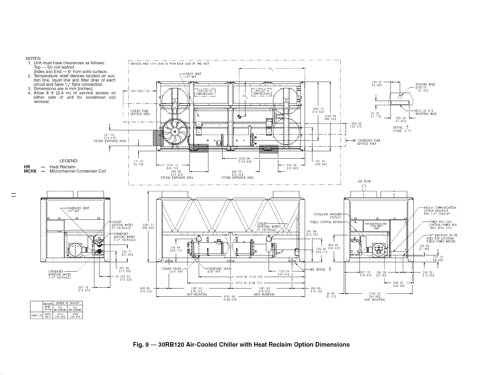
NOTES:
1. Unit must have clearances as follows:
Top -- Do not restrict.
Sides and End -- 6' from solid surface.
2. Temperature relief devices located on suc-
tion line, liquid line and filter drier of each
circuit and have 1/4"flare connection.
3. Dimensions are in mm [inches].
4. Allow 8 ft (2.4 m) of service access on
either side of unit for condenser coil
removal.
HR
MCHX --
50114
[199F]
PIPING ENTRANCE AREA
LEGEND
Heat Reclaim
Microchannel Condenser Coil
[SERVICE AREA 1219 2148 HI FROMEACH SIDE OF THE UNIT
I
: _÷OOLE_p_ENT
I
.-!447.978,
[
: COOLER TUBE
I SERVICE AREA
i
t
17147
1675]
[104,69]
107010 85904
[4213] [3382]
60000 60000
[2362] [2362]
PIPING ENTRANCE AREA PIPING ENTRANCE AREA
]
15 94] _ RIGGING HOLE
] 189275 1 ', 22 2[ 871
174 52] [1 771 J 200 00_
4500 MOUN:rI RG HOLE
2286 08
[88.03] i [7871
: [89.371 DETAIL _
I SCALE 3:10
F --q
1 _--HR CONDENSER TUBE
; I SERVICE AREA
,_,. _-
[30001
,I...... r II" 'nI
10_DE_;_8 VENT
R R n
_ OOLER
LEAVING WATER 228137
6" VICTAULIC 18982]
• LEAVING WATER
SO' VICTAULIC
342 96
[1350]
b07 19 40889
[19 97] [16101
WEIGHT CERTER OF GRAVITY
NCHX CGx CGy
Ib/kg [95001 [4287]
M_ lINCH] MM lINCH]
HOHH-120 8HOH 24_3 IOH9
3813
...... :,. : :- ,:,: :.:, :,:.,] :,. : : /.,.,: :.:, .,,.,
U
I29i'1 _, _ -
-+* Ii×'_O,0ENSER_PORAIN '_&_--
COOLER DRAIN
3/4;' NPT I 318" NPT I _ 1159 04
I
I
[45 63] I
341098 [134 29] I
I
i
377358 [148 57]
198165 ,,I, 198165 [
178 02] [78 02]
UNIT WOUNTING UNIT WOUNTING
[188.23]
SCROLl NAROUEE--
DISPLAY
FIELD CONTROL WIRING-
39188
D543]
I 86 0
738_9I3_:_21
[29 i] 1
--SEE DETA _
408 89
[1610]
3989
[15F]
AIR FLOW
I _ I I_ " I
.99..701
L-9_83s I
215680 [30941 .
[84 89]
UNIT MOUNTING
8ACDei COWWUNICATION
_OPTION KNOCKOUT
FOR 1/2" CONDUIT
POWER 80X 230V
_CONTROLIPOWER BOX
/ 380V,460V,575V
718" KNOCKOUT TO BE
USED FOR LOCATING
FIELD POWER WIRING
19000
1748]_
{' 21573
1849]
f f
33650
[1325]
Fig. 9 -- 30RB120 Air-Cooled Chiller with Heat Reclaim Option Dimensions
Co
SERVICE AREA 1219 2[48 O] FROM EACH SIDE OF THE UNIT r HOD OO ]A
=78 i 8765 •
m,. ,KAK,_/ .r I _°.
i! _O_=_ETX_EAII1°1_ I'1/ 11"1 4F_
!-"- 498.2F • 1693 76_ _ 116089 1040 9_
: [19 E2] [GR 68] [4D 70] [40 98]
i " H241 88 PIPING ENTRANCE AREA
[127 63]
r
,JJ
IJ TI
PUMP PACKAGE
PACKAGE
ENTERING WATER
6' VICFAULIC
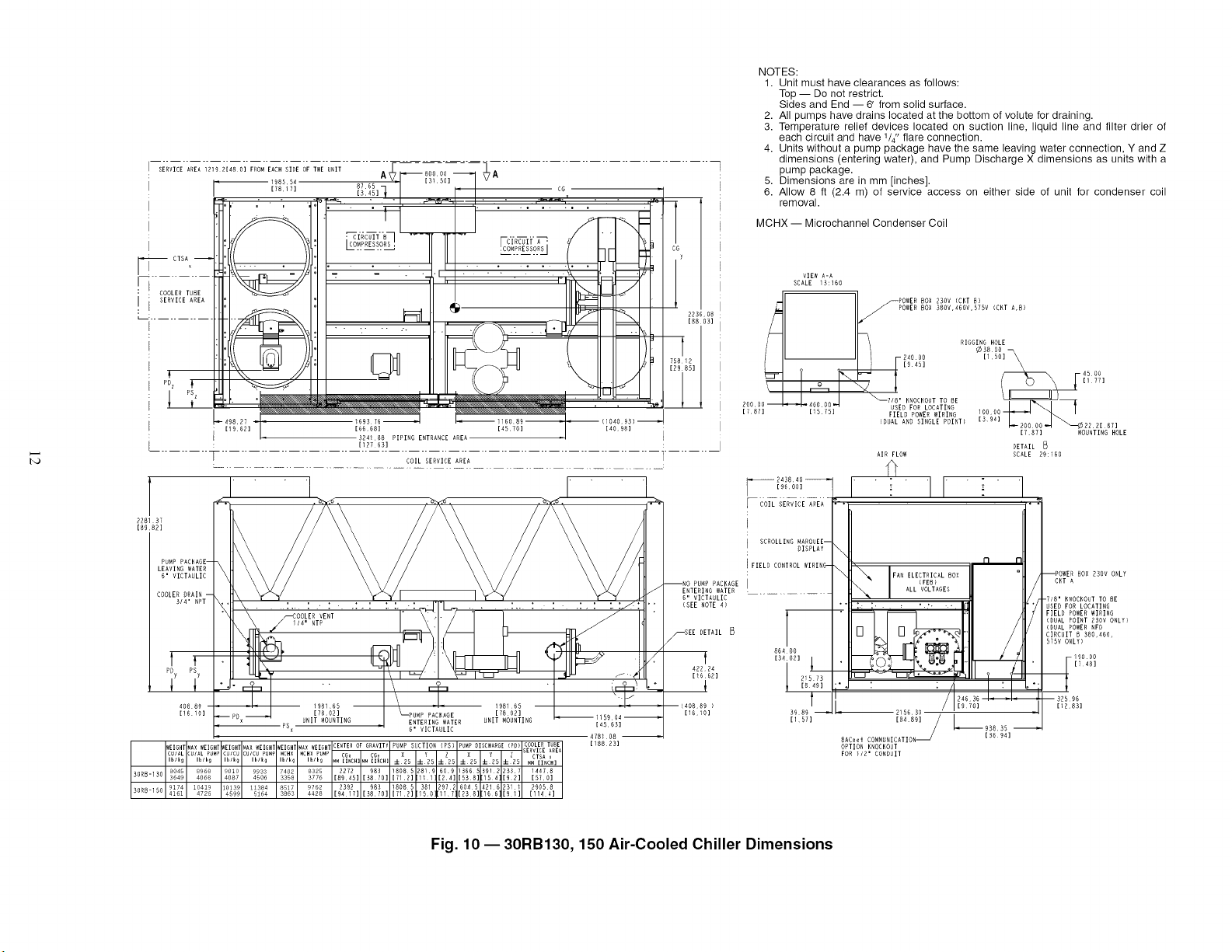
NOTES:
1. Unit must have clearances as follows:
Top -- Do not restrict.
Sides and End -- 6' from solid surface.
2. All pumps have drains located at the bottom of volute for draining.
3. Temperature relief devices located on suction line, liquid line and filter drier of
each circuit and have 1/4" flare connection.
4. Units without a pump package have the same leaving water connection, Y and Z
dimensions (entering water), and Pump Discharge X dimensions as units with a
pump package.
5. Dimensions are in mm [inches].
6. Allow 8 ft (2.4 m) of service access on either side of unit for condenser coil
removal.
MCHX -- Microchannel Condenser Coil
RVICE AREA =
/
\
200 O0--
[787]
VIEW A-A
SCALE 13:160
POWER DOX D3OV (CKT D)
POWER @OR 3DOV,460V,575V (CRT A,8)
RIGGING HOLE
¢3800_
J ! 24000 [150]
[945]
i 45 OR
Q I1 77]
._, _J _'_"HHOGHONTTOOE__
;De USEDEONLOGAFING__
[ 5 51 lOO DO
FIELD POWER AIRING
(DUAL AND SINGLE POINTI [394] 22 2[ 87]
[787] _OUNTIRG HOLE
DETAIL
AllOW SCALE 29:160
SCROLLI_,GAAROUEE--
DISPLAY
FIELD TROL WIRING-
.....
21573
[849]
39 AR
[15/]
\
• _;Q_C2f",._:_J' 1_] "
'H_DR'/ L____3D3D_
[36 941
_AC_i COAAUNICATION_
OPTION KNOCKO T
FOR )/2' CO@IT
--ROW 230V ONLY
CKT A
-718' HNOCKOUT TO BE
USED FOR LOCATING
FIELD POWER WIRING
(DUAL POINT 230V ONLY)
(DUAL POWER NFD
CIRCUIT _ 380,460,
575V ONLY)
-190 DO
32596
[1283]
Fig. 10- 30RB130, 150 Air-Cooled Chiller Dimensions
I
#
: .I COOLERTUBE
!iSERN'BBAREA
:6O0OO
1[BH H2]
PIPING :ENTERANCEAREA
I
it
:l/H OO
I IRBHI 123 HB] 123B21 .
L .......... !IP_N.!ENT_RANC!.AR__EA.................... P__'P.I._OE;'.TBRjR.?E__'R.E.'- .............................. i
1 I
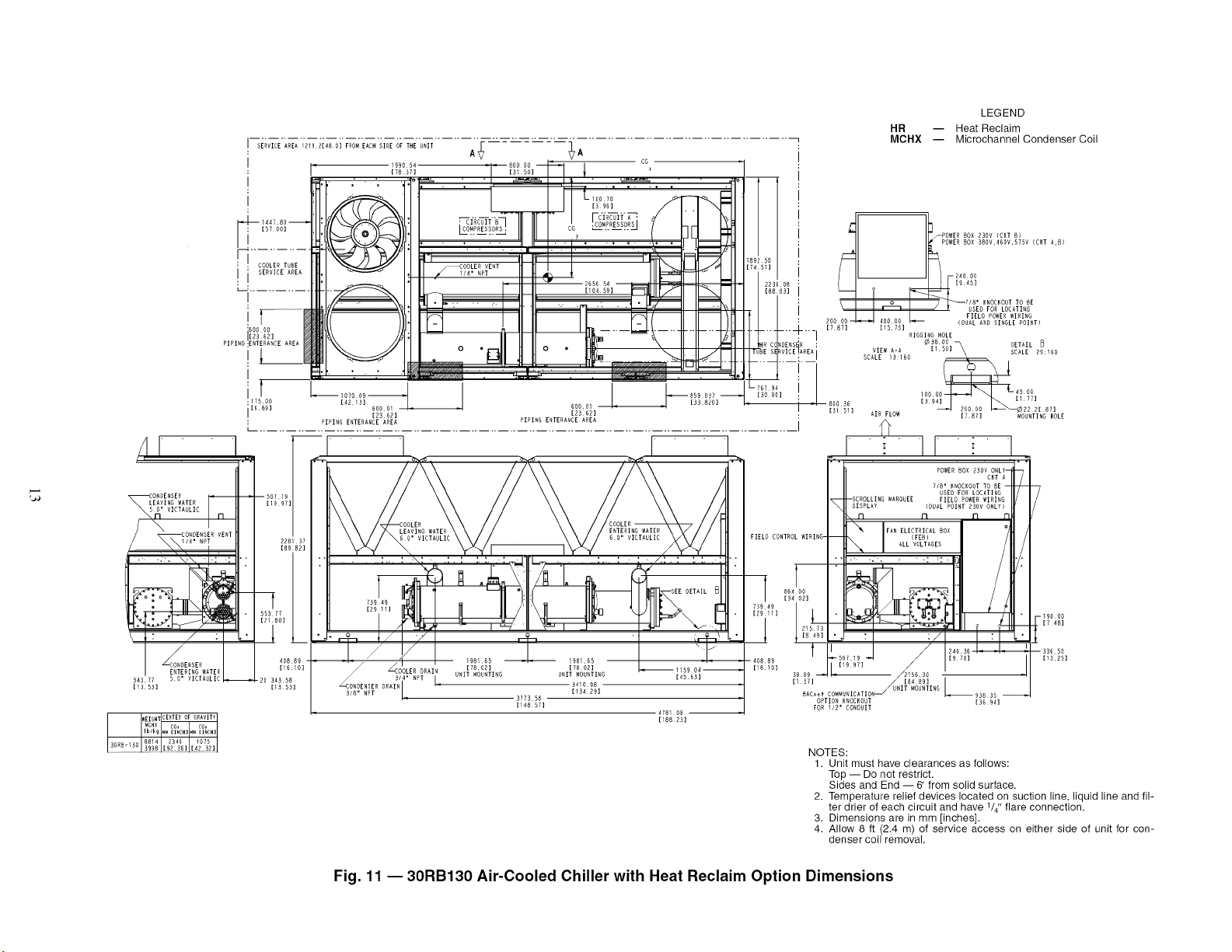
LEGEND
HR -- Heat Reclaim
MCHX -- Microchannel Condenser Coil
ORDENSER
LEAVING WATER
i_1" VICTANLIC
\
.+
49
11]
3DR WEIGHTCERTEROF GRAVITY8814
_-130 HRR8
POWER BOX H3OV {CRY B}
POWERBOX 380V,gHOV,DYHV [CRT A,B)
D31
i I/8" KNOCKOUT TO BE
_/ _BSED FOR LOCATIRG
: HOOOOJ_-J 4OOO0 _ FIELD POWER WIRING
{DUAL AND SINGLE POINT)
_..% [78Yl [15751
'-I RIGGING HOLE
38 OO _
" ' i_]\BETAIL D
_REAI VIEW A-A [IHO] SCALE
29:160
I SCALE 13:IHO
lOO nn_ _1 L4B OR
[_ 9_] [177]
[31511 AllOW [7871 MOUNTING HOLE
II
POWER BOX 23ON ONLY-
CRY A
7/8' RNOCROBT TO BE --
USED FOR LOCATING
-SCROLLING RARQBEE FIELD POWER WIRINGDISPLAY {DUAL POINT 2HOV ONLY)
n n n n
_'_ FAN ELECTRICAL(FEB)90X /
ALL VOLTAGES
• -190 09
[1 48]
33659
[192§]
96 90
19 9HI
39 89
[1 :::_t C.....ICATIOR_ UA]T NFLNTINO L'_HS8 9H
[3B 941
NOTES:
1. Unit must have clearances as follows:
Top -- Do not restrict.
Sides and End -- 6' from solid surface.
2. Temperature relief devices located on suction line, liquid line and fil-
ter drier of each circuit and have V4" flare connection.
3. Dimensions are in mm [inches].
4. Allow 8 ft (2.4 m) of service access on either side of unit for con-
denser coil removal.
Fig. 11 --30RB130 Air-Cooled Chiller with Heat Reclaim Option Dimensions
Z
SERVICE AREA 12_92140H] FROM EACH SIDE OF THE UNIT
7A
PU¢_ 290880
[H440]
I
i COOLER TUBE
SERVICE AREA
I--
OOOOO
[BR6B]
H4R!.... DDH-
GE'VENT"'RG'I I ,,.....
1/4" NPT _DX 343 58
[13 53]
WEIGHT CENTER OF GRAVITY
- _ 9929
30_8-1Rv 4504
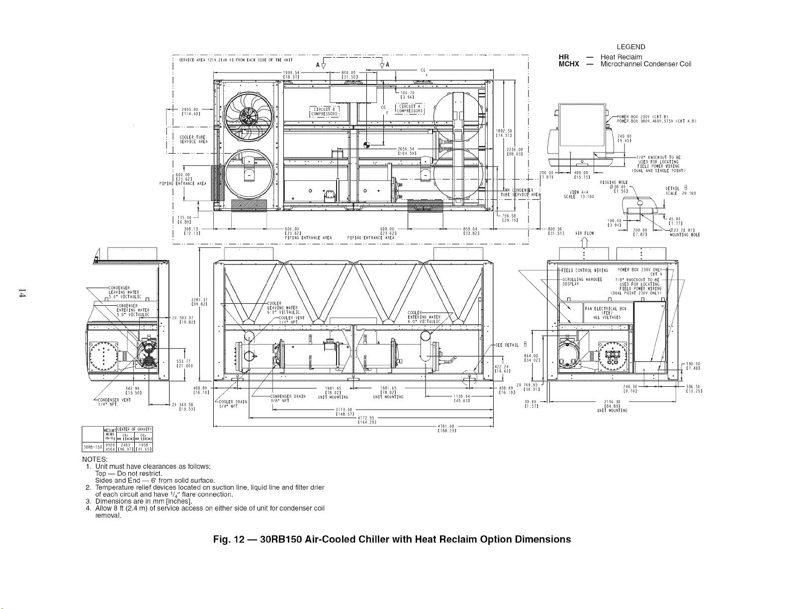
NOTES:
1. Unit must have clearances as follows:
Top -- Do not restrict.
Sides and End -- 6' from solid surface.
2. Temperature relief devices located on suction line, liquid line and filter drier
of each circuit and have 1/4" flare connection.
3. Dimensions are in mm [inches].
4. Allow 8 ft (2.4 m) of service access on either side of unit for condenser coil
removal.
78658
[R979]
OOLER
LEAVING WATER
.. X .:/. : .. : -. ,:,: :.:, .-:,:,,,_j .. ,;,., ; ,- ; -,/,.': ; ' ;, ,.'_'-_
I o / iH81HR _HSlHR
/
_ONDENSE8 DRAIN UNI_T8 021 [70021
MOUNTING RNIT MOUNTING _118904_
Of 8" NPT [45 BD]
OLER 0RAIR 3909
4' NRT I= [157]
3773 58
[14887] 417RRH
[16429]
478100 --
[188 8D]
8ETAIL _
8H4OO
[34 OR]
.. i
_- 40889 2x T6985 -
[HO31]
[161G]
LEGEND
HR -- Heat Reclaim
MCHX -- Microchannel Condenser Coil
80X DDOV (CRT 8)
POWER 50X DBOV,46OV,RTRV (CHT Ar5)
SOU B6
KNOCKOUT TO DE
USED FOR LOCATING
FIELD POWER WIRING
(DUAL AND SINGLE POINT)
[31Sl] AIR FLOW
E
RIGGIRG HOLE
RDOO _ UFTAII
5O ....
[ ] SCALE 29:160
Do0 00 I--,_'-_72 8[ 8T]
[78T] MOUNTING BOLE
FIELD CONTROL WIRING POWER 80x 8ROY ONLY-
GET A '
/
SCROLLING t_AROREE 718' HI,OCEO T TO 8E
81SPLAY USED FOR LOCATI G
FIELD POWER _VIRING
(DUAL POINT 2BOY ONLY)
"_ lq Fl Fl {q
.; .......
24636--
[H7O]
--190 OR
. [748]
1
--33650
[IDZ$]
2186H0
[8469]
UNIT MOUNTING
Fig. 12- 30RB150 Air-Cooled Chiller with Heat Reclaim Option Dimensions
SERVICE AREA 121921480] FROM EACH SIDE OF THE UNIT
I
I
r_ 14478
157001
r
COOLER TUBE
SERVICE AREA
RSz R9z
I I
76951
[3030]
i..... 7
I I
AV &
E
==CT_ l_///_./_///////////////////_.////////////////_///y/////_/_..-I_////////A
. .B3H3_ L----.sogs
i [58421 [57341
3212 K3 PIPING EHTRAHCE AREA
[12H 47]
I COIL SERVICE AREA
].............................
• "- " "- :. rrl C- "-"
@
,t
99325
[78 47]
WEIGHT_AX WEIGHT
CUIAL UUIAL PU_P
Iblk_ Iblk9
30RB-_40 10264 1151_
315AIB,330_ 4666 523Z
KORR-_IO I0_0_ 11846
50A•345A/N,KGOJ4B19 5385
228137 LEAVING WATER
[89 H2] 6" VICTAULIC
OOLER VERT I14' RPT i"
3/A" RPT)
,;i. ,-_ _- _..,_ ' 4,
408 89 - _!- R38[_\305, H" VICTA LIC 276_ 30[8184' _1_
[i6 10] IRA 01HI I [i0R 03]
UNIT MOUHTIRG I UNIT MOUNTING
RSx _ I _ 46406
[ H3 94]
[235 2HI
WEIGHT_AX WEIGHT WEIGHT AAXWIIGBl CENTER OF GRAVITY PUMPSUCTIO_ PU_APUISCBARGE(PR)
CU/C_ ZU/CU P_MP _CHX _ACHXPU_P CGx CG_
...................................... !25 ±!_5 ±!25 =H!25:1:!25
H4!2 _n7 94/5 107z0 N045 994 BOB 4 5SRlo] NN/ 2 NR392 42164 3_114
5215 5TNt 4297 4860 [120 66] [39 13] IT1 2] [1 [11 7] [_48] [166] [91]
]807 3052 9799 11044 _la 978 808 4; 381 297 2 885 92 4Rl_a 23114
5567 5933 4443 5009 [122 591 [3051 [71 21 [1R0] [11 71 [K481 [1561 19;1
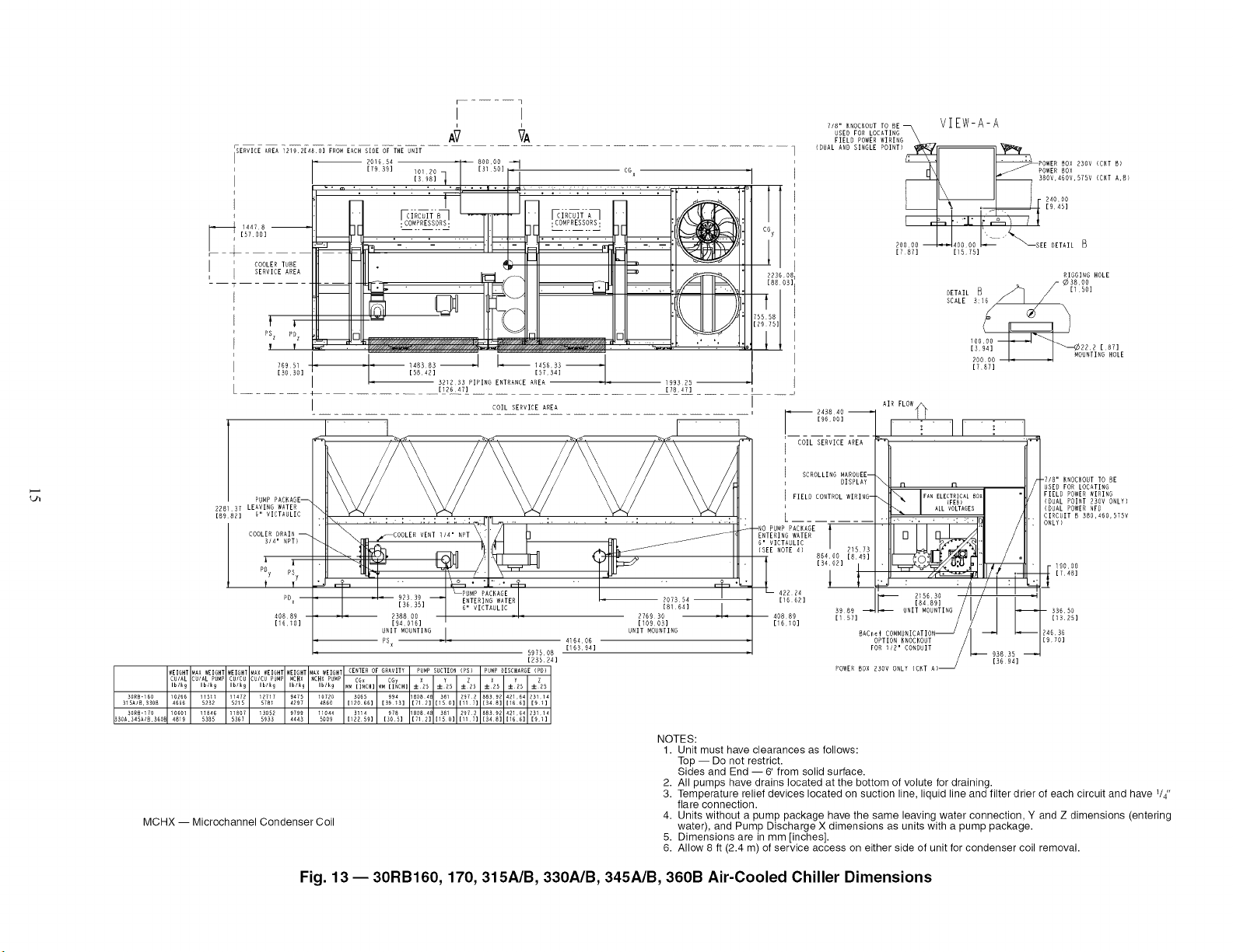
MCHX -- Microchannel Condenser Coil
l
CGy
1
R2_ 08
[He U3] I
t
75558
[29 751
1
//8" KAODKOUTTO BE _ VIEW-A-A
SED FOR LOCATING
FIELD POWER WIRIG
<DUAL AND SIHGLE POIRT)
POWER BOX 2SOY {CKT R)
POWER BOX
380V,46OV,575V (CKT A,B}
: 24000
19 45]
200 D0 4,JNOO OR L--" "'Z_""",,._SEE DETAIL E}
[7BK] [1§ l§]
RIGGING HOLE
/- ¢3800
RETAIL B _/A] / [ 50]
SCALE 3:16
[787]
I
, _ 249840
[9HOO]
COIL SERVICE AREA
SCROLLING MARQUEE--
DISPLAY
FIELB CONTROL WIRING-
-_
1 WATER
H' VICTAULIC
{SE NOTE 4)
86400 [84R]
422 24
[16 HE]
40889
1i6101
AIR FLOW_
_1 i' II i'
n n
FAN ELECTRICALBOX
(FEB)
:._ I ALLVOLTAGESI
It_ : °,
215630
3989 _ _ UNIT MONTIHG
[ KK]
BAC_¢i COFA_AUAICATION
OPTION KNOCKOUT
FOR 112' CORBUIT
93835
[36 94]
POWER BOX 230V ONLY (CHT A)_
-7/8" KNOCKOUT TO BE
USED FOR LOCATING
FIELD ROWER WIRING
(DUAL ROIHT 230V OHLY)
_DUAL POWER NFD
CIRCUIT R 380,4HO,KYSV
OHLY)
- 9000
[148]
-- 33650
[1325]
24636
[gYo]
NOTES:
1. Unit must have clearances as follows:
Top -- Do not restrict•
Sides and End --6' from solid surface•
2. All pumps have drains located at the bottom of volute for draining•
3. Temperature relief devices located on suction line, liquid line and filter drier of each circuit and have VA"
flare connection•
4. Units without a pump package have the same leaving water connection, Y and Z dimensions (entering
water), and Pump Discharge X dimensions as units with a pump package•
5. Dimensions are in mm [inches]•
6. Allow 8 ft (2.4 m) of service access on either side of unit for condenser coil removal•
Fig. 13- 30RB160, 170, 315A/B, 330A/B, 345A/B, 360B Air-Cooled Chiller Dimensions
CONDENSERS
ENTERING WATER
80' VICTAULIC
2X 34333 --
[13 521
WEIGHT CENTER OF GRAVITY
_CHX CG_ CGy
Ib/_9 _M [l_CN] _M lINCH]
30RN-160 I0991 3124 _001
3_SAIB,3308 4986 [122991 [394]1
30RN-I?O 11315 3168 98_
330A,345AIB,360_ 5_33 [124741 [38821
2X 503 31 228
[i0 82] [89 8_]
-_ONOENSER
LEAVING WATER
50" VICTAULIC
583!81
8ol ,
343_8_
113,841
K/4' NRT
SCROLLING _AROUEE-
DISPLAY
FIELD CONTROL WIRING
864!00
2x 76985 [34 0R]
.08_1I L
40889
[1610]
RAChel
OPTION KNOCKOUT
FOR 1/2' CONDUIT
7/8' KNOCKOUT TO BE
USEO FOR LOCATING
FIELD POWER WIRING
_DUAL POINT 230V ONLY)
19000
[9A81
:i_
L 83650
[13251
24536
[970]
93835 _'J
[3094]
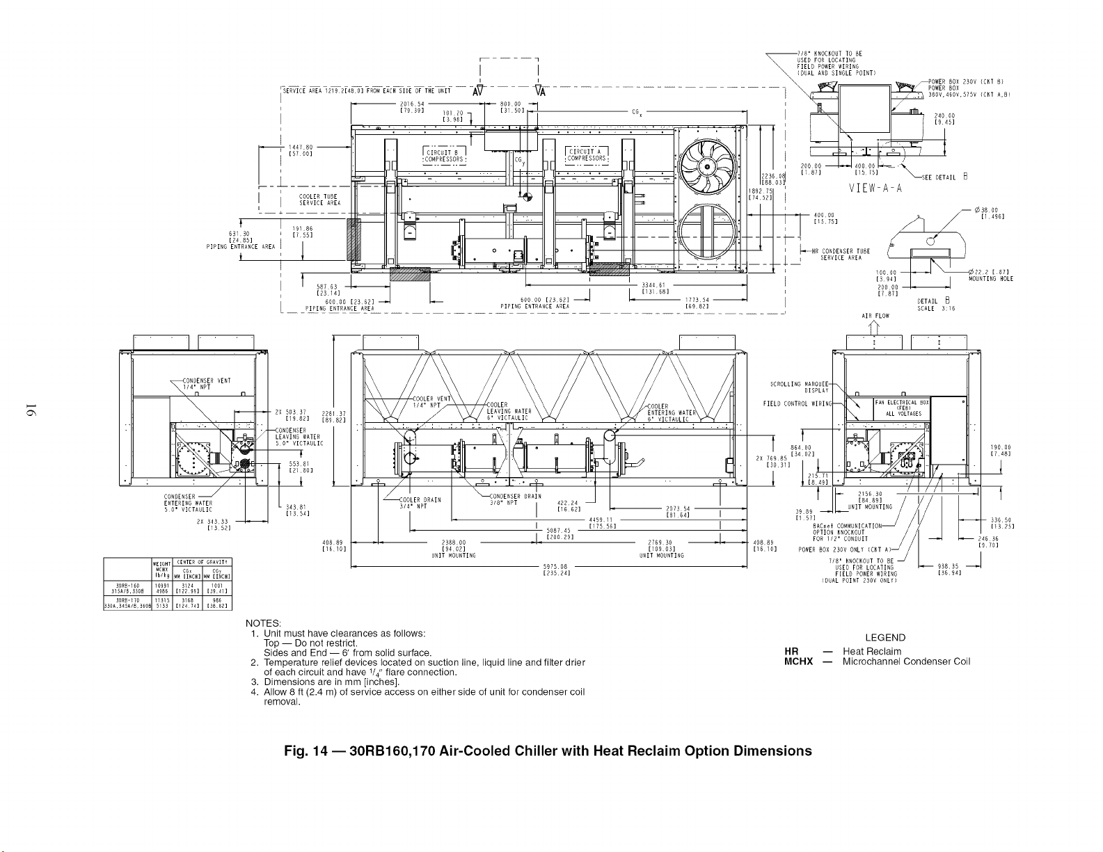
NOTES:
1. Unit must have clearances as follows:
Top -- Do not restrict.
Sides and End -- 6' from solid surface.
2. Temperature relief devices located on suction line, liquid line and filter drier
of each circuit and have VA"flare connection.
3. Dimensions are in mm [inches].
4. Allow 8 ft (2.4 m) of service access on either side of unit for condenser coil
removal.
HR
MCHX
LEGEND
-- Heat Reclaim
-- Microchannel Condenser Coil
Fig. 14 -- 30RB160,170 Air-Cooled Chiller with Heat Reclaim Option Dimensions
r SERVICE AREA 1219 2148 O] FRON EACH SIDE OF THE £,NIT
! "
I
!
I
F! 96040
[3F 811
I [SERVICE AREI
I
LJ
!
I
|
I,
iP:I
PSz J
-- 196374
[F7311
F--
•I..... ]
A_7 VA
\'_-tFt!-J/
/€::::=11 II:::::_\
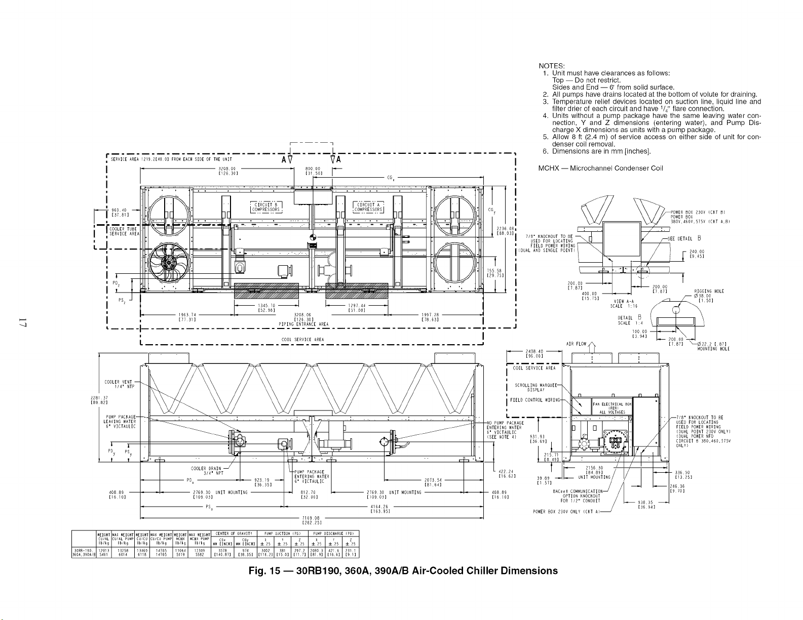
NOTES:
1. Unit must have clearances as follows:
Top -- Do not restrict.
Sides and End --6' from solid surface.
2. All pumps have drains located at the bottom of volute for draining.
3. Temperature relief devices located on suction line, liquid line and
filter drier of each circuit and have 1/4" flare connection.
4. Units without a pump package have the same leaving water con-
nection, Y and Z dimensions (entering water), and Pump Dis-
charge X dimensions as units with a pump package.
5. Allow 8 ft (2.4 m) of service access on either side of unit for con-
denser coil removal.
6. Dimensions are in mm [inches].
, MCHX -- Microchannel Condenser Coil
"1 !
C 7 POV,'ERBOX
_80V,NEOV,PlSV (CHT A,B)
2236 08!
I [88 03]| 7/8' HROCHOUT TOIE _
l USED FOR LOIATI G
I FIELD POWER WIR HG [-- DETAIL B
(DUAL AND SINGLE POINT) _ 2NOOO
I ' L ,R,P,
_:_, ! _-
// I _o0oo
_ I [7871
!
I
|
I
L
==.- -=r
b .i
12974.__I[PE98] [5108]
320806 199728
[12630] 17863]
PIPING ENTRANCE AREA
I
COIL SERVICE AREA
.J
I
!
I
!
J
243840
[9DOO]
l COIL SERVICE AREA
!
l SCROLLING MARQUEE--
DISPLAY
i FIELG COHTROLWIRIRG-
!
L .....
WATER T
93193
IRK R9] 1
I 21571
[8491
f
(SEE NOTE 4)
SCALE 1:16
DETAIL
SCALE 1:4
8AC_¢i
OPTION KNOCKOUT
FOR i12" COHDUIT_
POWER BOX _3OV ONLY (CKT A)
RIGGING HOLE
-- ¢380P
[87]
MOUNTING HOLE
_7/8' KNOCKOUT TO BE
USED FOR LOCATING
FIELD POWER WIRING
(DUAL POINT ERPV ONLY)
(DUAL POWER RFD
CIRCUIT B 38D,NHO,575V
ONLY)
- 33650
[1325]
24636
[R FO]
Fig. 15 --30RB190, 360A, 390A/B Air-Cooled Chiller Dimensions
OR,DENSER VE'_T
_ONDE_SENI
WEIGHT CENTER OF GRAVITY
_CHX CG CGy
Iblk9 H_ [I_CH] MM [I_CH]
360A,_90A_ $706 [140_9] [385_]SORD-_90 128S0 3566 _79
i
A?
COOLER DRAI_S
[28225]
CG
_i 60000
3344 54
[13167]
SCROLLING MAROVEE_
FIELD CONTROL WIRI_6
T
9_400
[SGlF]
39 8
408
[6
[394]
[7 87]
o
-l!......
[9 70]
BAC_el COMF'U_ICATIO, _ 93835
OPTION RROCKO_T _ [3S 94]
FOR IE" CONDVIT I /
POWER BOX 230v ONLY (CNT A)_ I
7/8" RNOCKOVT TO BE _
USED FOR LOCATIRG
FIELD POWER WIRIRG
(DUAL _OINT 2_OV O_LY)
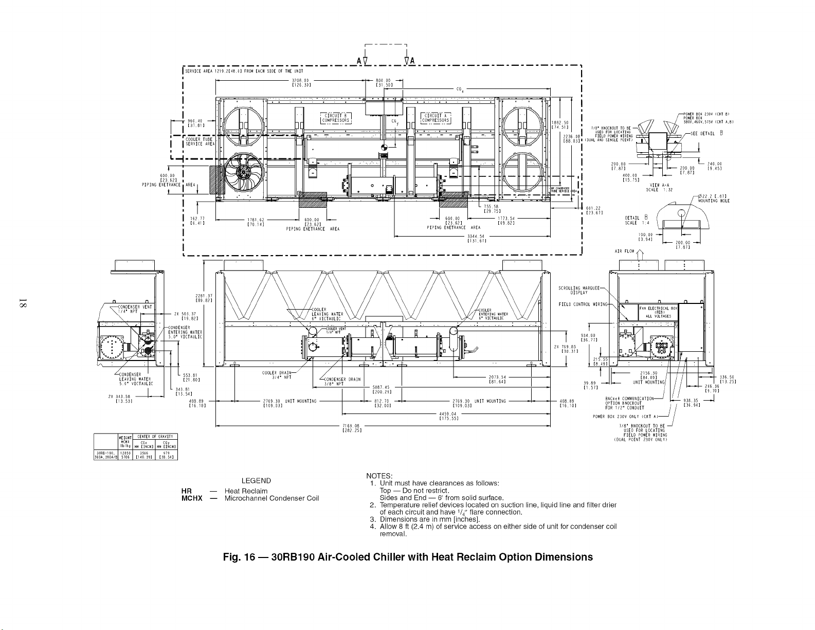
LEGEND
HR -- Heat Reclaim
MCHX -- Microchannel Condenser Coil
NOTES:
1. Unit must have clearances as follows:
Top -- Do not restrict.
Sides and End -- 6' from solid surface.
2. Temperature relief devices located on suction line, liquid line and filter drier
of each circuit and have V4" flare connection.
3. Dimensions are in mm [inches].
4. Allow 8 ft (2.4 m) of service access on either side of unit for condenser coil
removal.
Fig. 16- 30RB190 Air-Cooled Chiller with Heat Reclaim Option Dimensions
I SERVICE AREA 1219 2148 O] FROM EACH SIDE OF THE UNIT
I"_ I 14478 L_ .....
: COOLER T
J ISERVICE_AI
[3i 50]
POWERBOX 2 _" .....
2NOVWRLY ......
CIRCUIT H
• - CO_4PRESSORS
POW[R BOX I
2_OvCKIB
_OV,_S_VmDV
_//_///A. i i. v///////_, _//////////////////////////////////_ TUT--
K3OD_--4 I_ ,8Ks22
[DO 652 ] [74 221 ]
199054
[78 31]
t_
• x
• .. _T _ - ..
,CO'_PRESSORS,
223(
700 39
i 1256 59 _22217 PIPIR¢ ENTR%RCE AREA 2690 K2
[12686]
_ _ _ .R_:_.................................................................................. _!_9_,....... __..................
........... COIL SERVICE AREA I
COOLER
228137 i/4' NPT
[8982] LEAVIRG WI[ER-
6" VICTAULIC
COOLER
3/4'
• • L 4378H
[1724] 43786 J \_
[17241 _ENTERING WATER
6" VICTAULIC
40889 157530 • • 279435 198105 40889
[1E1O] [6202] / [1i001] [7802] [i6iO]
UNIT MOUNTINGJ UNIT MOUNTING UNIT MOUNTING
-- IR_R _R 280654
1530D] [I1049]
I169 08
[28225]
WEIGHT WEIGHT WEIGHT CENTER OF GRAVITY
CUIAL CU/CU MCHX CG CGy
Ib/k9 Ib/k9 Ib/kR W_ [I_GH] MW LINCH]
KOR_-210 _37S4 _5_81 _2772 3528 9H
624D 6901 5793 [13890] [3610]
_4067 _5514 _3093 3588 906
KORK-225 6394 7052 5937 [_4_26] [3567]
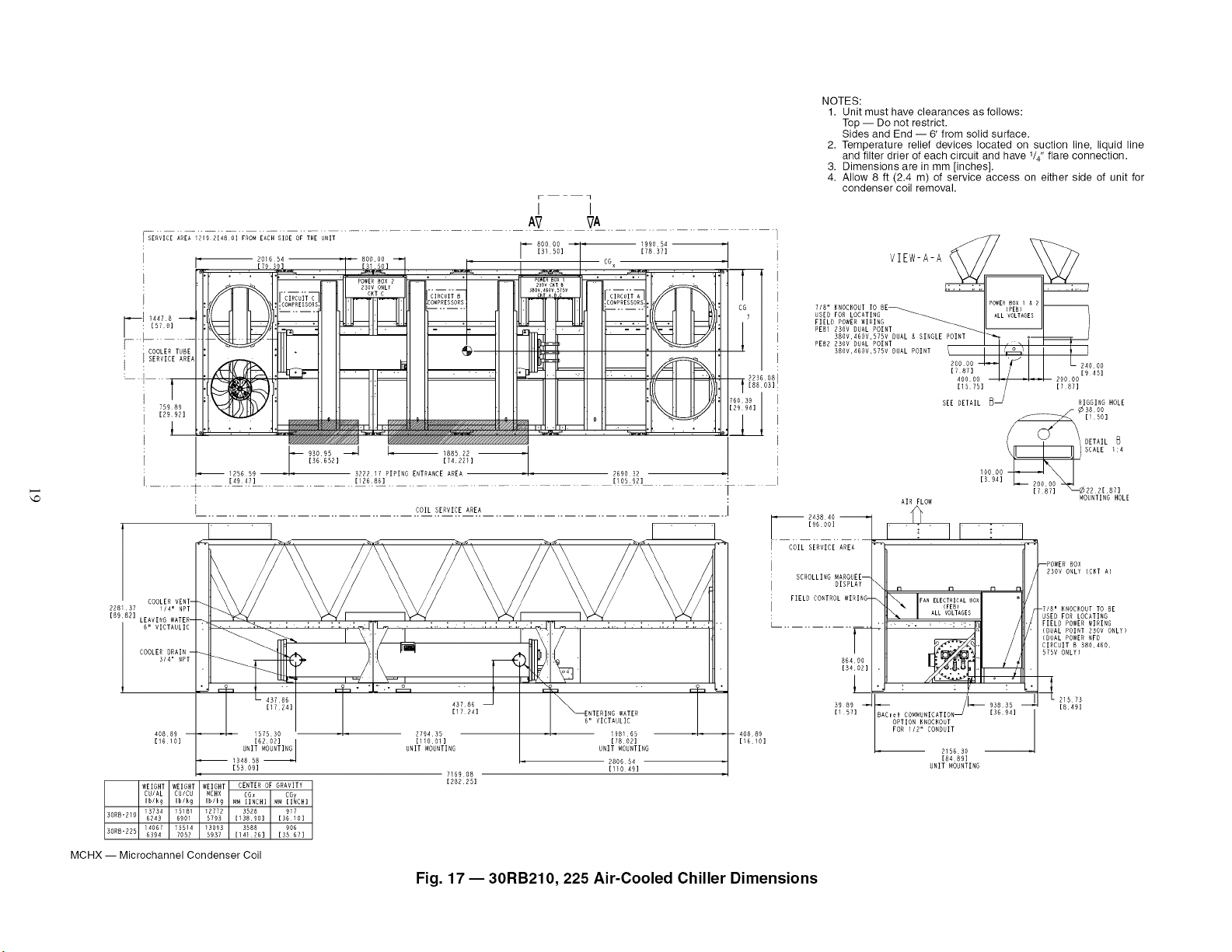
NOTES:
1. Unit must have clearances as follows:
Top -- Do not restrict•
Sides and End -- 6' from solid surface•
2. Temperature relief devices located on suction line, liquid line
and filter drier of each circuit and have V4" flare connection•
3. Dimensions are in mm [inches]•
4. Allow 8 ft (2.4 m) of service access on either side of unit for
condenser coil removal•
VIEW-A-A
718" KNOCKOUT
USEO FOR LOCATING
FIELD POWER WIRING
PE812NOV DUAL POINT
(_¢38 O0
[i 50]
DETAIL
I00D01394]_SCALER2 2[ 8Y11:4
AIR FLOW MOUNTING HOLE
Do, I ' II I
COIL SERVICE AREA
: SCROLLING MAROUEE--
i DISPLAY
i FIELD CONTROL WIRING-
L ........T
80400
[34102]
3989
[157]
--P( B0X
230V ONLY {CKT A)
/
n n n n /
/
ALL VOLTAGES -7 8' NNOCKOUT TO BE
USED FOR LOCATING
........ "" ' : : " Ib _ / FIELD POWER WIRING
(DUAL POWER RFO
•. CU IT B 380,460,
.. 57! ONLY)
/1_ I 2_sKs
93835 _ 8 49
BAC_ef COMMUNICATION _ [36941
OPTION KHOCNOUT
FOR 112" CONDUIT
215HS0
[8489]
UNIT WOUNTING
MCHX -- Microchannel Condenser Coil
Fig. 17- 30RB210, 225 Air-Cooled Chiller Dimensions
I,O
A A
_SESERVICEAREA 9219214H0] FROM EACH SIDE OF THE UNIT 990 54 SCALE I: 6
I • 3_DA_3 .... 80000_ _"
12429 :01 2O 7 3150 = =,
I : "'" ; ''_i ..... "'" :': "J" "'" ; SEEDETAIL 6
i _ _ 24000
4478
['_[5700] ]E : '- : ]E ............. CGy
::: ttl/ 7/8" KNOCKOUTTO BE_ '\'J' '
08II USED FOR LOCATING 40000 ,_ _,::, 20000
FIELD POWER WIRIHG [1575] [787A]
........................ [88 03] I PEB1 POINT
380V,A6OV,D75V DUAL & SIHGLE POIHT
_ _ PEB2 ALL VOLTAGES DUAL POIHT
RIGGIHG HOLE
/- _3800
] DETAIL _ _ .... _._ [150]
[4016] [7645] [3 ]
241618 3253173 PIPING ENTRANCE AREA 269373 UNTING HOLE
" [9513] [1280777] [10605] i 20000
.............................................................................................................................. [787]
.................................. _.olA S!R_!A_ER....................................
[329 26]
I---;::!°:; :LO,.f ......
SGROL ;#L :ROUEEq'-I10 n II
_ 93835 _
[1571 ef COFA_UHICATIOH [36941
40889
[16 10] OPTION KHOCHOUT
FOR /2' EOt_DUIT
2 56 30
[84 89]
UNIT MOUNTIHG
21575
[849]
f
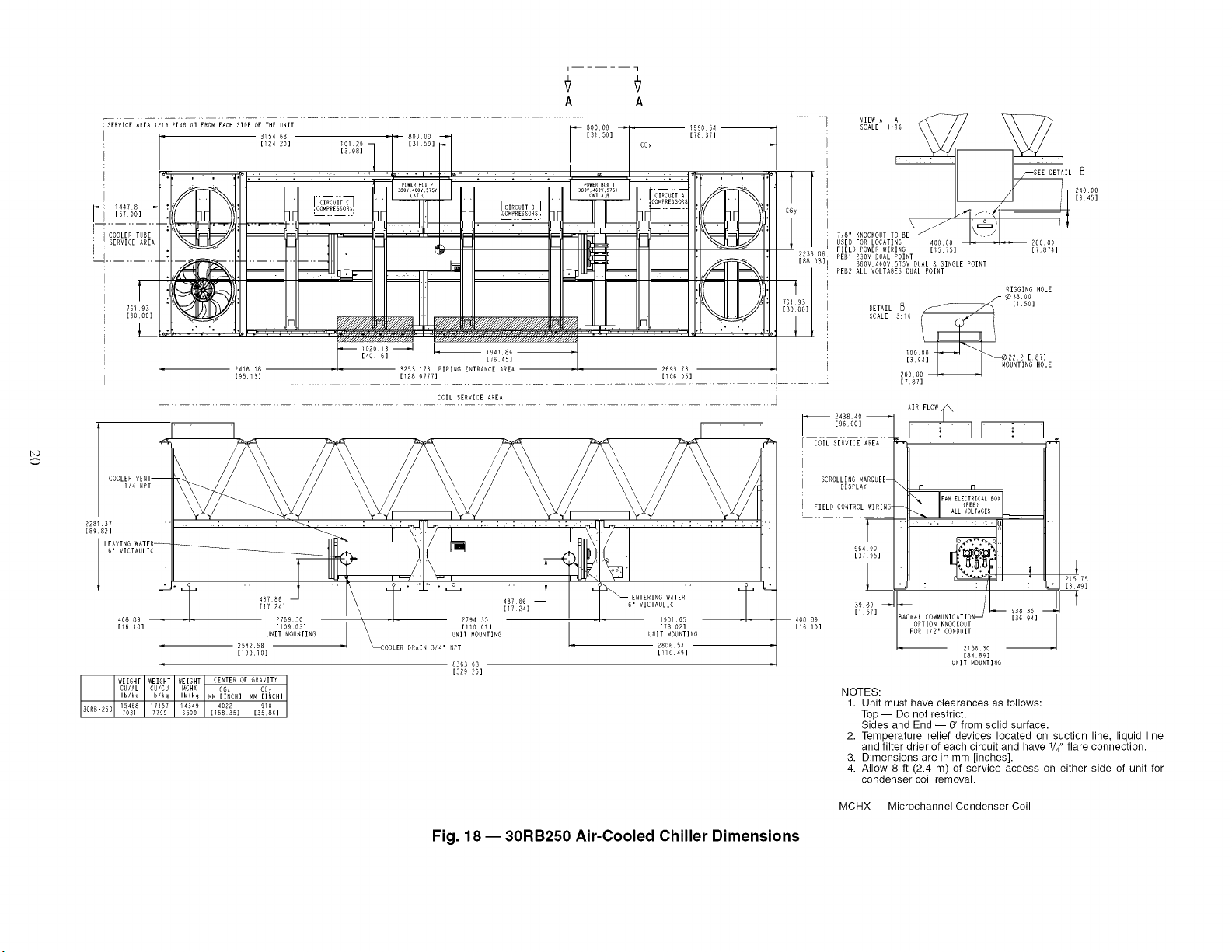
NOTES:
1. Unit must have clearances as follows:
Top -- Do not restrict.
Sides and End -- 6' from solid surface.
2. Temperature relief devices located on suction line, liquid line
and filter drier of each circuit and have V4" flare connection.
3. Dimensions are in mm [inches].
4. Allow 8 ft (2.4 m) of service access on either side of unit for
condenser coil removal.
MCHX -- Microchannel Condenser Coil
Fig. 18- 30RB250 Air-Cooled Chiller Dimensions
I'D
• i
SERVICE AREA 1219 2148 O] FRO_ EACH SIDE OF THE _,RIT
I
i: r_ZO16SA R:GRDO ,,1, ,1 HGDOD
[31 50]
j [79 3D] [ 09 53]
I .:_.E3D6 .:oH,o:.=,o, . :. : -;,
CIRCUITC_ ...... "CIRCUIT_ I CIRCUITA_
I
" 2097 Al 3227 68 D,o_i, r_TD^_rr _Dr_ A23i 79
[82 56] [27061 [16H g ]
I
: COIL SERVICE AREA
L
I
T
CGy
1
223608 :
[66 [
t
75939
[299D:
1
I
..... j__ ,__
........... j
VIEW A - A
SCALE 9:160
SEE DETAIL B
POWER ELECTRICAL i0_
7/8" KNOCKOUT TO BE 40606 2O0O0
F_R_LOCATING [15 75] [787]
SED
FIELD POWER WIRING
PEG1 230V DUAL POINT
: 380V,466V,S75V DUAL & SINGLE POINT
PEG2 ALL VOLTAGES DUAL POINT
RIGGING HOLE
DETHIL_
SCALE 9:40 [1501
4500
r"TlI [_j !_
,DoDo4---_'--..i q
[394] _- 20000 --"4_ '_ (
' MOUHTING HOLE
AIR FLOW
_..:-_.!Ii6°!!_..- - _ _
COILSERVICE_REA_ _
SCROLLING"_RONEE--.II II
OISRLA,\LO 0 tl
L: FIELD CONTROL.......WIRING- _ ray....._L_C_IC_LBOX _I l
AG_6R 6Kc0. HIRATION ?_2_, J _;!I_D_
h_ 215630
[84691
UNIT MOHRTING
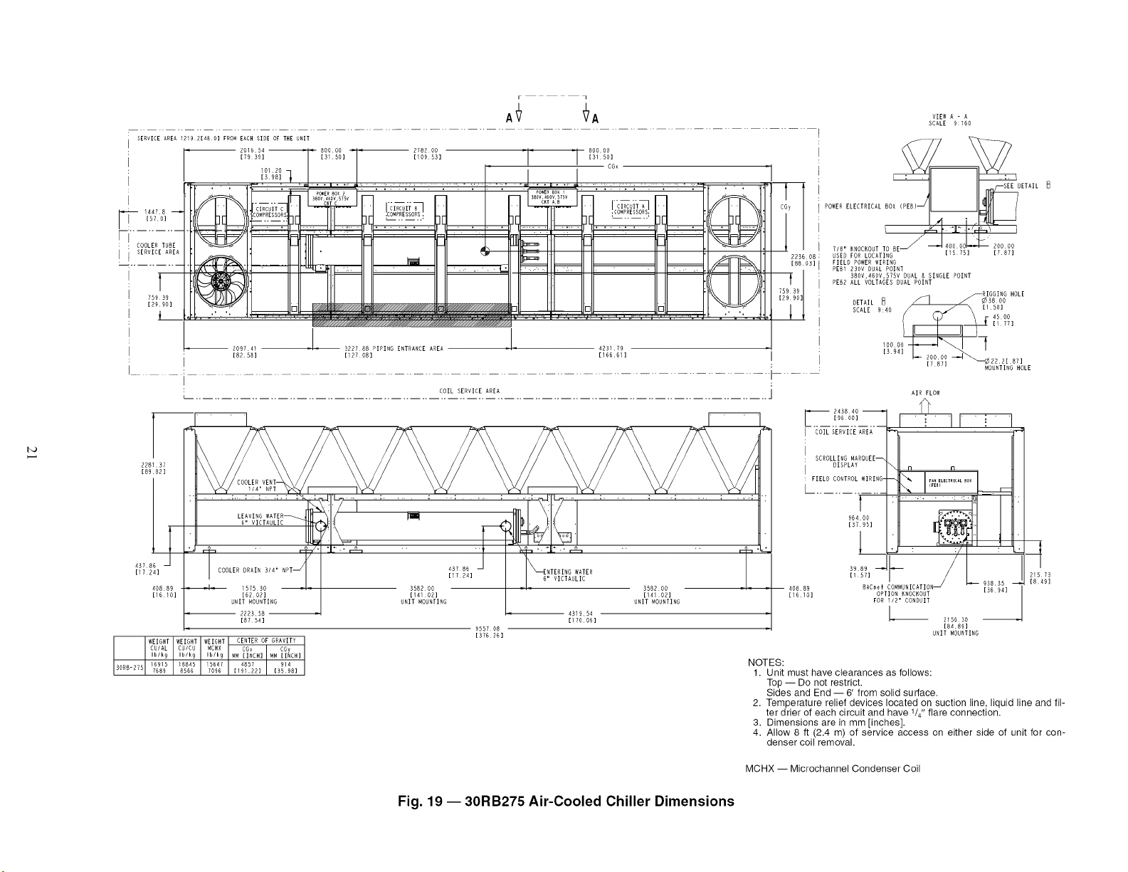
NOTES:
1. Unit must have clearances as follows:
Top -- Do not restrict.
Sides and End --6' from solid surface.
2. Temperature relief devices located on suction line, liquid line and fil-
ter drier of each circuit and have V4" flare connection.
3. Dimensions are in mm [inches].
4. Allow 8 ft (2.4 m) of service access on either side of unit for con-
denser coil removal.
MCHX -- Microchannel Condenser Coil
Fig. 19- 30RB275 Air-Cooled Chiller Dimensions
 Loading...