


AQUASNAP® 30RAP010-060 Liquid Chillers
with COMFORTLINKTM Controls
Installation Instructions
CONTENTS
Page SAFETY CONSIDERATIONS . . . . . . . . . . . . . . . . . . . . . . 1
INSTALLATION . . . . . . . . . . . . . . . . . . . . . . . . . . . . . . . . 1-31
Step 1 — Rig and Place the Unit. . . . . . . . . . . . . . . . . . 1
•RIGGING
•PLACING UNIT
•MOUNTING UNIT
Step 2 — Check Compressor Mounting . . . . . . . . . . 6
Step 3 — Cooler Fluid and Drain Piping
Connections . . . . . . . . . . . . . . . . . . . . . . . . . . . . . . . . . . . 6
•ALL UNITS
•UNITS WITH FACTORY-INSTALLED HYDRONIC PACKAGES
•AIR SEPARATION
Step 4 — Fill the Chilled Water Loop . . . . . . . . . . . . 15
•WATER SYSTEM CLEANING
•FILLING THE SYSTEM
•PREPARATION FOR YEAR-ROUND OPERATION
•FREEZE PROTECTION
•PREPARATION FOR WINTER SHUTDOWN
Step 5 — Make Electrical Connections . . . . . . . . . . 20
•POWER SUPPLY
•POWER WIRING
•FIELD CONNECTIONS
Step 6 — Install Accessories . . . . . . . . . . . . . . . . . . . . 29
• ELECTRICAL
Step 7 — Check Refrigerant Circuit . . . . . . . . . . . . . 29
•LEAK TESTING
•DEHYDRATION
•REFRIGERANT CHARGE
APPENDIX A (Pressure Drop Curves) . . . . . . . . 32-38
SAFETY CONSIDERATIONS
Installing, starting up, and servicing air-conditioning equipment can be hazardous due to system pressures, electrical components, and equipment location (roofs, elevated structures, etc.).
Only trained, qualified installers and service mechanics should install, start up, and service this equipment (Fig. 1).
Untrained personnel can perform basic maintenance functions such as cleaning coils. All other operations should be performed by trained service personnel.
When working on the equipment, observe precautions in the literature and on tags, stickers, and labels attached to the equipment.
•Follow all safety codes.
•Wear safety glasses and work gloves.
•Keep quenching cloth and fire extinguisher nearby when brazing.
•Use care in handling, rigging, and setting bulky equipment.
These instructions cover installation of 30RAP010-060 air-cooled liquid chillers. Refer to Fig. 2 for model number to determine factoryinstalled options.
.
 WARNING
Electrical shock can cause personal injury and death. Shut off all power to this equipment during installation. There may be more than one disconnect switch. Tag all disconnect locations to alert others not to restore power until work is completed.
INSTALLATION
Step 1 — Rig and Place the Unit
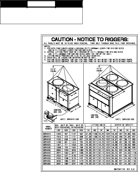
RIGGING — Preferred method for rigging is with spreader bars from above the unit. Use hooks in lifting holes. Rig at a single point with 4 cables or use spreader bars. All panels must be in place when rigging. See rigging label on unit for details concerning shipping weights, distance between lifting holes, center of gravity, and lifting ring dimensions. See Tables 1A and 1B for physical data. Refer to Fig. 3 for unit weights. See Fig. 4 for rigging label.
If overhead rigging is not possible, place chiller on skid or pad for rolling or dragging. When rolling, use a minimum of 3 rollers. When dragging, pull the pad. Do not apply force to the unit. When in final position, raise from above to lift unit off pad.
 CAUTION
All panels must be in place when rigging. Damage to unit could result.
PLACING UNIT — There must be at least 3 ft (0.9 m) for service and for unrestricted airflow on all non-coil sides of unit, and a minimum of 3.5 ft (1.1 m) clear air space on coil sides. For multiple units, allow 8 ft (2.48 m) separation between units for airflow and service.
Fig. 1 — Typical 30RAP Unit (018-030 Shown)
Manufacturer reserves the right to discontinue, or change at any time, specifications or designs without notice and without incurring obligations.
Catalog No. 04-53300036-01 |
Printed in U.S.A. |
Form 30RAP-1SI |
Pg 1 |
11-09 |
Replaces: New |
30RA P 010 6 D A 0 6 0 0 0
30RA – Air-Cooled AquaSnap Chiller
Refrigerant Type
P – Puron®
Unit Sizes
010 025 045
015 030 050
018 035 055
020 040 060
Voltage
1 – 575-3-60
2 – 380-3-60
5– 208/230-3-60
6– 460-3-60
Condenser Coil/Low Sound Options
5– MCHX, Value Sound Fan
6– MCHX, E-coat, Value Sound Fan
D – |
MCHX, AeroAcoustic™ Fan |
F – |
MCHX, E-coat, AeroAcoustic Fan |
J– MCHX, AeroAcoustic Fan, Ultra-Low Sound
K– MCHX, E-coat, AeroAcoustic Fan, Ultra-Low Sound
Revision Level
A – Current Revision Level
Hydronic System
0– No Pump
1– Single Pump, 1 Hp
2– Single Pump, 1.5 Hp
3– Single Pump, 2 Hp
4– Single Pump, 3 Hp
5– Single Pump, 5 Hp
6– Single Pump, 5 Hp High Head
7– Single Pump, 7.5 Hp
8– Dual Pump, 1 Hp
9– Dual Pump, 1.5 Hp
B– Dual Pump, 2 Hp
C– Dual Pump, 3 Hp
D– Dual Pump, 5 Hp
F– Dual Pump, 5 Hp High Head
G– Dual Pump, 7.5 Hp
Packaging/Security Options
0 |
– |
Std Packaging |
4 |
– |
Security Grilles/Hail Guards Only |
8 |
– |
Skid Only |
D – |
Skid, Security Grilles/Hail Guards |
|
J |
– |
Skid, Top Crate, Bag |
N – |
Skid, Top Crate, Bag, Security Grilles/Hail Guards |
|
|
||
Controls/Communications Options |
||
0 |
– |
Std |
5 |
– |
EMM |
B – |
EMM, GFI |
|
Electrical Options
0– No Disconnect, No Cooler Heater
1– No Disconnect, Cooler Heater
D – |
Non-Fused Disconnect, No Cooler Heater |
F – |
Non-Fused Disconnect, Cooler Heater |
Ambient/Capacity Control/Interrupt Options
0– Std Comp, Std Interrupt
1– Hot Gas Bypass, Std Interrupt
2– Digital Comp, Std Interrupt
3– Std Comp, High SCCR
4– Hot Gas Bypass, High SCCR
5– Digital Comp, High SCCR
6– Low Ambient, Std Comp, Std Interrupt
7– Low Ambient, Hot Gas Bypass, Std Interrupt
8– Low Ambient, Digital Comp, Std Interrupt
9– Low Ambient, Std Comp, High SCCR
B– Low Ambient, Hot Gas Bypass, High SCCR
C– Low Ambient, Digital Comp, High SCCR
LEGEND
EMM — Energy Management Module
GFI — Ground Fault Interrupting
SCCR — Short Circuit Current Rating
Quality Assurance
Certified to ISO 9001: 2000
Fig. 2 — AQUASNAP® Chiller Model Number Designation
2
STANDARD UNITS
30RAP |
|
|
POUNDS |
|
|
SIZE |
A |
B |
C |
D |
Total |
|
Weight |
||||
|
|
|
|
|
|
010 |
188 |
209 |
161 |
146 |
704 |
015 |
193 |
213 |
163 |
149 |
718 |
018 |
363 |
264 |
209 |
288 |
1125 |
020 |
365 |
266 |
211 |
290 |
1133 |
025 |
393 |
290 |
237 |
321 |
1242 |
030 |
405 |
301 |
246 |
331 |
1283 |
035 |
652 |
730 |
413 |
369 |
2163 |
040 |
704 |
697 |
390 |
394 |
2185 |
045 |
675 |
758 |
425 |
379 |
2238 |
050 |
732 |
724 |
401 |
405 |
2263 |
055 |
744 |
762 |
437 |
427 |
2369 |
060 |
746 |
762 |
438 |
429 |
2375 |
30RAP |
|
|
KILOGRAMS |
|
||
SIZE |
A |
B |
C |
D |
Total |
|
Weight |
||||||
|
|
|
|
|
||
010 |
85.5 |
94.6 |
73.1 |
66.1 |
319.3 |
|
015 |
87.7 |
96.4 |
74.1 |
67.4 |
325.5 |
|
018 |
164.9 |
119.9 |
94.9 |
130.6 |
510.3 |
|
020 |
165.8 |
120.8 |
95.8 |
131.5 |
513.9 |
|
025 |
178.3 |
131.8 |
107.7 |
145.7 |
563.5 |
|
030 |
183.7 |
136.3 |
111.6 |
150.4 |
582.0 |
|
035 |
295.7 |
331.0 |
187.2 |
167.2 |
981.1 |
|
040 |
319.4 |
316.3 |
176.9 |
178.5 |
991.1 |
|
045 |
306.3 |
344.0 |
193.0 |
171.9 |
1015.1 |
|
050 |
332.2 |
328.4 |
181.8 |
183.9 |
1026.3 |
|
055 |
337.4 |
345.5 |
198.2 |
193.5 |
1074.6 |
|
060 |
338.4 |
345.8 |
198.6 |
194.5 |
1077.3 |
|
SINGLE PUMP UNITS
30RAP |
|
|
POUNDS |
|
|
SIZE |
A |
B |
C |
D |
Total |
|
Weight |
||||
|
|
|
|
|
|
010 |
215 |
264 |
213 |
174 |
866 |
015 |
220 |
268 |
215 |
177 |
880 |
018 |
404 |
306 |
249 |
329 |
1288 |
020 |
406 |
308 |
251 |
331 |
1296 |
025 |
434 |
332 |
277 |
362 |
1405 |
030 |
446 |
342 |
286 |
372 |
1446 |
035 |
740 |
814 |
499 |
453 |
2507 |
040 |
791 |
783 |
475 |
480 |
2529 |
045 |
763 |
843 |
512 |
463 |
2582 |
050 |
819 |
810 |
486 |
491 |
2606 |
055 |
831 |
847 |
522 |
512 |
2713 |
060 |
833 |
848 |
523 |
514 |
2719 |
30RAP |
|
|
KILOGRAMS |
|
||
SIZE |
A |
B |
C |
D |
Total |
|
Weight |
||||||
|
|
|
|
|
||
010 |
97.6 |
119.8 |
96.7 |
78.9 |
393.0 |
|
015 |
99.8 |
121.6 |
97.7 |
80.2 |
399.3 |
|
018 |
183.4 |
138.7 |
112.8 |
149.2 |
584.0 |
|
020 |
184.3 |
139.6 |
113.7 |
150.1 |
587.6 |
|
025 |
196.9 |
150.5 |
125.6 |
164.2 |
637.2 |
|
030 |
202.2 |
155.1 |
129.5 |
168.9 |
655.7 |
|
035 |
335.6 |
369.4 |
226.3 |
205.6 |
1137.0 |
|
040 |
358.8 |
355.3 |
215.4 |
217.5 |
1147.0 |
|
045 |
346.3 |
382.3 |
232.1 |
210.2 |
1171.0 |
|
050 |
371.6 |
367.4 |
220.4 |
222.9 |
1182.2 |
|
055 |
376.9 |
384.3 |
236.9 |
232.3 |
1230.5 |
|
060 |
378.0 |
384.6 |
237.3 |
233.3 |
1233.2 |
|
DUAL PUMP UNITS
30RAP |
|
|
POUNDS |
|
|
|
SIZE |
A |
B |
C |
|
D |
Total |
|
Weight |
|||||
|
|
|
|
|
|
|
010 |
242 |
319 |
266 |
|
202 |
1029 |
015 |
247 |
323 |
268 |
|
205 |
1043 |
018 |
445 |
347 |
288 |
|
370 |
1450 |
020 |
447 |
349 |
290 |
|
372 |
1458 |
025 |
475 |
373 |
316 |
|
403 |
1567 |
030 |
487 |
383 |
325 |
|
413 |
1608 |
035 |
828 |
899 |
585 |
|
538 |
2850 |
040 |
878 |
869 |
560 |
|
565 |
2872 |
045 |
851 |
928 |
598 |
|
548 |
2925 |
050 |
906 |
896 |
571 |
|
577 |
2950 |
055 |
918 |
933 |
607 |
|
598 |
3056 |
060 |
920 |
933 |
608 |
|
600 |
3062 |
30RAP |
|
|
KILOGRAMS |
|
||
SIZE |
A |
B |
C |
D |
Total |
|
Weight |
||||||
|
|
|
|
|
||
010 |
109.9 |
144.8 |
120.5 |
91.5 |
466.7 |
|
015 |
112.1 |
146.6 |
121.4 |
92.8 |
473.0 |
|
018 |
202.0 |
157.4 |
130.7 |
167.7 |
657.7 |
|
020 |
202.9 |
158.3 |
131.6 |
168.6 |
661.3 |
|
025 |
215.5 |
169.2 |
143.5 |
182.7 |
710.9 |
|
030 |
220.8 |
173.8 |
147.4 |
187.3 |
729.4 |
|
035 |
375.5 |
407.9 |
265.3 |
244.2 |
1292.9 |
|
040 |
398.2 |
394.2 |
254.0 |
256.5 |
1302.9 |
|
045 |
386.2 |
420.8 |
271.1 |
248.8 |
1326.9 |
|
050 |
411.0 |
406.4 |
258.9 |
261.8 |
1338.1 |
|
055 |
416.4 |
423.2 |
275.6 |
271.2 |
1386.3 |
|
060 |
417.5 |
423.4 |
276.0 |
272.1 |
1389.1 |
|
30RAP010-030 UNITS |
|
30RAP035-060 UNITS |
|
B |
C |
B |
C |
CONTROL |
|
|
CONTROL |
|
|
BOX |
|
|
BOX |
|
|
SIDE |
|
|
SIDE |
|
|
|
|
|
a30-4861 |
|
|
|
|
|
|
|
|
A |
D |
A |
D |
||
Fig. 3 — Unit Operating Weights
3
Table 1A — Physical Data, 30RAP — English
UNIT 30RAP |
|
|
010 |
|
|
015 |
|
018 |
|
020 |
|
025 |
|
030 |
|
|
035 |
|
040 |
|
045 |
|
050 |
|
055 |
|
060 |
|
OPERATING WEIGHT (lb) |
|
|
|
|
|
|
|
|
|
|
|
|
|
|
|
|
|
|
|
|
|
|
|
|
|
|
||
MCHX Condenser Coil, No Pump |
|
704 |
|
|
718 |
|
1125 |
|
1133 |
|
1242 |
|
1283 |
|
|
2163 |
|
2185 |
|
2238 |
|
2263 |
|
2369 |
|
2375 |
||
|
|
|
|
|
|
|
|
|
|
|
|
|||||||||||||||||
MCHX Condenser Coil, Single Pump |
|
866 |
|
|
880 |
|
1288 |
|
1296 |
|
1405 |
|
1446 |
|
|
2507 |
|
2529 |
|
2582 |
|
2606 |
|
2713 |
|
2719 |
||
MCHX Condenser Coil, Dual Pump |
|
1029 |
|
|
1043 |
|
1450 |
|
1458 |
|
1567 |
|
1608 |
|
|
2850 |
|
2872 |
|
2925 |
|
2950 |
|
3056 |
|
3062 |
||
REFRIGERANT TYPE |
|
|
|
|
|
|
|
|
|
|
R-410A, EXV Controlled System |
|
|
|
|
|
|
|
|
|||||||||
Total Refrigerant Charge (lb) |
|
8.6 |
|
|
9.6 |
|
14.6 |
|
15.2 |
|
16.7 |
|
17.6 |
|
|
29.2 |
|
29.9 |
|
33.5 |
|
33.7 |
|
34.3 |
|
34.5 |
||
|
|
|
|
|
|
|
|
|
|
|
|
|||||||||||||||||
Refrigerant Charge (lb) Ckt A/Ckt B |
|
8.6/— |
|
|
9.6/— |
|
14.6/— |
|
15.2/— |
|
16.7/— |
|
17.6/— |
|
|
14.3/14.9 |
|
14.9/15.0 |
|
16.5/17.0 |
|
16.7/17.0 |
|
16.9/17.4 |
|
17.1/17.4 |
||
COMPRESSORS |
|
|
|
|
|
|
|
|
|
|
|
|
Scroll, Hermetic |
|
|
|
|
|
|
|
|
|
|
|||||
Quantity |
|
|
1 |
|
|
1 |
|
2 |
|
2 |
|
2 |
|
2 |
|
|
4 |
|
4 |
|
4 |
|
4 |
|
4 |
|
4 |
|
|
|
|
|
|
|
|
|
|
|
|
|
|
||||||||||||||||
Speed (Rpm) |
|
|
|
|
|
|
|
|
|
|
|
|
|
3500 |
|
|
|
|
|
|
|
|
|
|
||||
(Qty, Tons) Ckt A |
|
(1) 11 |
|
|
(1) 15 |
|
(2) 9 |
|
(2) 10 |
|
(2) 13 |
|
(2) 15 |
|
|
(2) 10 |
|
(2) 10 |
|
(2) 11 |
|
(2) 13 |
|
(2) 13 |
|
(2) 15 |
||
|
|
|
|
|
|
|
|
|
|
|
|
|||||||||||||||||
(Qty, Tons) Ckt B |
|
— |
|
|
— |
|
— |
|
— |
|
— |
|
— |
|
|
(2) 9 |
|
(2) 11 |
|
(2) 13 |
|
(2) 13 |
|
(2) 15 |
|
(2) 15 |
||
Oil Charge (Pt) Ckt A/Ckt B |
|
6.9/— |
|
|
6.9/— |
|
13.8/— |
|
13.8/— |
|
13.8/— |
|
13.8/— |
|
|
13.8/13.8 |
|
13.8/13.8 |
|
13.8/13.8 |
|
13.8/13.8 |
|
13.8/13.8 |
|
13.8/13.8 |
||
No. Capacity Steps |
|
|
|
|
|
|
|
|
|
|
|
|
|
|
|
|
|
|
|
|
|
|
|
|
|
|
||
Standard |
|
|
1 |
|
|
1 |
|
2 |
|
2 |
|
2 |
|
2 |
|
|
4 |
|
4 |
|
4 |
|
4 |
|
4 |
|
4 |
|
With Hot Gas Bypass |
|
— |
|
|
— |
|
3 |
|
3 |
|
3 |
|
3 |
|
|
5 |
|
5 |
|
5 |
|
5 |
|
5 |
|
5 |
||
Digital Compressor Option |
|
13 |
|
|
13 |
|
— |
|
22 |
|
22 |
|
22 |
|
|
44 |
|
44 |
|
44 |
|
44 |
|
44 |
|
44 |
||
Minimum Capacity Step (%) |
|
|
|
|
|
|
|
|
|
|
|
|
|
|
|
|
|
|
|
|
|
|
|
|
|
|
||
Standard |
|
|
100 |
|
|
100 |
|
50 |
|
50 |
|
50 |
|
50 |
|
|
23 |
|
23 |
|
24 |
|
25 |
|
23 |
|
25 |
|
With Hot Gas Bypass |
|
— |
|
|
— |
|
20 |
|
24 |
|
29 |
|
32 |
|
|
10 |
|
12 |
|
14 |
|
14 |
|
15 |
|
16 |
||
Digital Compressor Option |
|
20 |
|
|
20 |
|
— |
|
15 |
|
15 |
|
15 |
|
|
8 |
|
8 |
|
8 |
|
8 |
|
8 |
|
8 |
||
Capacity (%) |
|
|
|
|
|
|
|
|
|
|
|
|
|
|
|
|
|
|
|
|
|
|
|
|
|
|
||
Circuit A |
|
|
100 |
|
|
100 |
|
100 |
|
100 |
|
100 |
|
100 |
|
|
54 |
|
47 |
|
47 |
|
50 |
|
46 |
|
50 |
|
Circuit B |
|
|
— |
|
|
— |
|
— |
|
— |
|
— |
|
— |
|
|
46 |
|
53 |
|
53 |
|
50 |
|
54 |
|
50 |
|
COOLER |
|
|
|
|
|
|
|
|
|
Brazed, Direct-Expansion Plate Heat Exchanger |
|
|
|
|
|
|
|
|
||||||||||
Weight (lb) (empty) |
|
22.4 |
|
|
27.5 |
|
31.8 |
|
40.3 |
|
46.3 |
|
80.6 |
|
|
99.4 |
|
117.9 |
|
125.3 |
|
137.5 |
|
160.4 |
|
160.4 |
||
|
|
|
|
|
|
|
|
|
|
|
||||||||||||||||||
Net Fluid Volume (gal) |
|
4.9 |
|
|
6.4 |
|
7.6 |
|
10.1 |
|
11.7 |
|
16.5 |
|
|
21.8 |
|
27.5 |
|
29.3 |
|
34.3 |
|
41.8 |
|
41.8 |
||
Maximum Refrigerant Pressure (psig) |
|
505 |
|
|
505 |
|
505 |
|
505 |
|
505 |
|
565 |
|
|
565 |
|
565 |
|
565 |
|
565 |
|
565 |
|
565 |
||
Maximum Water-Side Pressure |
|
300 |
|
|
300 |
|
300 |
|
300 |
|
300 |
|
300 |
|
|
300 |
|
300 |
|
300 |
|
300 |
|
300 |
|
300 |
||
Without Pump(s) (psig) |
|
|
|
|
|
|
|
|
|
|
|
|
|
|
||||||||||||||
|
|
|
|
|
|
|
|
|
|
|
|
|
|
|
|
|
|
|
|
|
|
|
|
|
|
|||
Maximum Water-Side Pressure |
|
150 |
|
|
150 |
|
150 |
|
150 |
|
150 |
|
150 |
|
|
150 |
|
150 |
|
150 |
|
150 |
|
150 |
|
150 |
||
With Pump(s) (psig) |
|
|
|
|
|
|
|
|
|
|
|
|
|
|
||||||||||||||
|
|
|
|
|
|
|
|
|
|
|
|
|
|
|
|
|
|
|
|
|
|
|
|
|
|
|||
CHILLER WATER CONNECTIONS (in.) |
|
|
|
|
|
|
|
|
|
|
|
|
|
|
|
21/2 |
|
21/2 |
|
21/2 |
|
21/2 |
|
21/2 |
|
21/2 |
||
Inlet and Outlet, Victualic |
|
2 |
|
|
2 |
|
2 |
|
2 |
|
2 |
|
2 |
|
|
|
|
|
|
|
||||||||
Drain (NPT) |
|
|
1/2 |
|
|
1/2 |
|
1/2 |
|
1/2 |
|
1/2 |
|
1/2 |
|
|
1/2 |
|
1/2 |
|
1/2 |
|
1/2 |
|
1/2 |
|
1/2 |
|
CONDENSER FANS |
|
|
|
|
|
|
|
|
|
|
|
|
|
|
|
|
|
|
|
|
|
|
|
|
|
|
||
Standard Low-Sound AeroAcoustic™ |
|
|
|
|
|
|
|
|
|
|
Plastic Type, Axial, Vertical Discharge |
|
|
|
|
|
|
|
|
|||||||||
Type |
|
|
|
|
|
|
|
|
|
|
|
|
|
|
|
|
|
|
|
|
|
|
|
|
|
|
|
|
Fan Speed (Rpm) |
|
850 |
|
|
850 |
|
850 |
|
850 |
|
850 |
|
850 |
|
|
850 |
|
850 |
|
850 |
|
850 |
|
850 |
|
850 |
||
|
|
|
|
|
|
|
|
|
|
|
|
|||||||||||||||||
No. Blades...Diameter (in.) |
|
9...30 |
|
|
9...30 |
|
9...30 |
|
9...30 |
|
9...30 |
|
9...30 |
|
|
9...30 |
|
9...30 |
|
9...30 |
|
9...30 |
|
9...30 |
|
9...30 |
||
No. Fans |
|
|
1 |
|
|
1 |
|
2 |
|
2 |
|
2 |
|
2 |
|
|
3 |
|
3 |
|
3 |
|
3 |
|
4 |
|
4 |
|
Total Airflow (Cfm) |
|
9400 |
|
|
9400 |
|
17,500 |
|
17,500 |
|
19,400 |
|
19,400 |
|
|
29,600 |
|
29,500 |
|
29,300 |
|
30,500 |
|
38,800 |
|
38,800 |
||
Optional Value Sound Type |
|
|
|
|
|
|
|
|
|
|
Propeller |
|
Type, Axial, |
|
Vertical |
Discharge |
|
|
|
|
|
|
|
|
||||
Fan Speed (Rpm) |
|
1140 |
|
|
1140 |
|
1140 |
|
1140 |
|
1140 |
|
1140 |
|
|
1140 |
|
1140 |
|
1140 |
|
1140 |
|
1140 |
|
1140 |
||
|
|
|
|
|
|
|
|
|
|
|
|
|||||||||||||||||
No. Blades...Diameter (in.) |
|
4...30 |
|
|
4...30 |
|
4...30 |
|
4...30 |
|
4...30 |
|
4...30 |
|
|
4...30 |
|
4...30 |
|
4...30 |
|
4...30 |
|
4...30 |
|
4...30 |
||
No. Fans |
|
|
1 |
|
|
1 |
|
2 |
|
2 |
|
2 |
|
2 |
|
|
3 |
|
3 |
|
3 |
|
3 |
|
4 |
|
4 |
|
Total Airflow (Cfm) |
|
12,600 |
|
|
12,600 |
|
23,400 |
|
23,400 |
|
26,000 |
|
26,000 |
|
|
39,800 |
|
39,600 |
|
39,300 |
|
41,000 |
|
52,100 |
|
52,100 |
||
CONDENSER COILS |
|
|
|
|
|
|
|
|
|
|
Novation® MCHX Aluminum Tube, Aluminum Fin |
|
|
|
|
|
|
|
|
|||||||||
Quantity (Ckt A/Ckt B) |
|
1/— |
|
|
1/— |
|
1/— |
|
1/— |
|
1/— |
|
1/— |
|
|
1/1 |
|
1/1 |
|
1/1 |
|
1/1 |
|
1/1 |
|
1/1 |
||
Total Face Area (sq ft) |
|
17 |
|
|
17 |
|
26 |
|
26 |
|
33 |
|
33 |
|
|
53 |
|
53 |
|
66 |
|
66 |
|
66 |
|
66 |
||
Maximum Refrigerant Pressure (psig) |
|
656 |
|
|
656 |
|
656 |
|
656 |
|
656 |
|
656 |
|
|
656 |
|
656 |
|
656 |
|
656 |
|
656 |
|
656 |
||
HYDRONIC MODULE (Optional)* |
|
|
Pump(s), Strainer with Blowdown Valve, Expansion Tank, Pressure Taps, Drain and Vent Plugs, Flow Switch, and Balance Valve |
|||||||||||||||||||||||||
Pump |
|
|
|
|
|
|
Single or Dual, Centrifugal Monocell Pump(s), 3500 Rpm. Dual pumps with check valves and isolation valves. |
|
|
|||||||||||||||||||
Expansion Tank Volume (gal) |
|
|
|
|
|
|
|
|
|
|
|
|
|
|
|
|
|
|
|
|
|
|
|
|
|
|
||
|
|
|
|
|
|
|
|
|
|
|
|
|
|
|
|
|
|
|
|
|
|
|
|
|
|
|||
Total/Acceptance |
|
|
|
|
|
5.0/2.9 |
|
|
|
|
|
|
|
|
|
10.0/5.5 |
|
|
|
|
||||||||
CHASSIS DIMENSIONS (ft - in.) |
|
|
|
|
|
|
|
|
|
|
|
|
|
|
|
|
|
|
|
|
|
|
|
|
|
|
||
Length |
|
|
5-7 |
|
|
5-7 |
|
7-5 |
|
7-5 |
|
7-5 |
|
7-5 |
|
|
7-5 |
|
7-5 |
|
7-5 |
|
7-5 |
|
7-5 |
|
7-5 |
|
|
|
|
|
|
|
|
|
|
|
|
|
|
||||||||||||||||
Width |
|
|
|
3-5 |
|
|
3-5 |
|
3-5 |
|
3-5 |
|
3-5 |
|
3-5 |
|
|
7-9 |
|
7-9 |
|
7-9 |
|
7-9 |
|
7-9 |
|
7-9 |
Height |
|
|
5-6 |
|
|
5-6 |
|
5-6 |
|
5-6 |
|
6-6 |
|
6-6 |
|
|
5-6 |
|
5-6 |
|
6-6 |
|
6-6 |
|
6-6 |
|
6-6 |
|
|
LEGEND |
|
|
|
|
|
|
|
|
|
*Flow switch and strainer are standard on all units, with or without hydronic package. |
|||||||||||||||||
EXV |
— |
Electronic Expansion Valve |
|
|
|
|
|
|
|
|
|
|
|
|
|
|
|
|
|
|
|
|
|
|
|
|
|
|
MCHX |
— |
Microchannel Heat Exchanger |
|
|
|
|
|
|
|
|
|
|
|
|
|
|
|
|
|
|
|
|
|
|
|
|
|
|
4
Table 1B — Physical Data, 30RAP — SI
UNIT 30RAP |
|
|
010 |
|
|
015 |
|
018 |
|
020 |
|
025 |
|
030 |
|
|
035 |
|
040 |
|
045 |
|
050 |
|
055 |
|
|
060 |
|
OPERATING WEIGHT (kg) |
|
|
|
|
|
|
|
|
|
|
|
|
|
|
|
|
|
|
|
|
|
|
|
|
|
|
|
||
MCHX Condenser Coil, No Pump |
|
319 |
|
|
326 |
|
510 |
|
514 |
|
564 |
|
582 |
|
|
981 |
|
991 |
|
1015 |
|
1026 |
|
1075 |
|
|
1077 |
||
|
|
|
|
|
|
|
|
|
|
|
|
||||||||||||||||||
MCHX Condenser Coil, Single Pump |
|
393 |
|
|
399 |
|
584 |
|
588 |
|
637 |
|
656 |
|
|
1137 |
|
1147 |
|
1171 |
|
1182 |
|
1231 |
|
|
1233 |
||
MCHX Condenser Coil, Dual Pump |
|
467 |
|
|
473 |
|
658 |
|
661 |
|
711 |
|
729 |
|
|
1293 |
|
1303 |
|
1327 |
|
1338 |
|
1386 |
|
|
1389 |
||
REFRIGERANT TYPE |
|
|
|
|
|
|
|
|
|
|
R-410A, EXV Controlled System |
|
|
|
|
|
|
|
|
|
|||||||||
Total Refrigerant Charge (kg) |
|
3.9 |
|
|
4.4 |
|
6.6 |
|
7.1 |
|
7.6 |
|
8.0 |
|
|
13.4 |
|
13.6 |
|
15.6 |
|
15.7 |
|
16.0 |
|
|
16.1 |
||
|
|
|
|
|
|
|
|
|
|
|
|
||||||||||||||||||
Refrigerant Charge (kg) Ckt A/Ckt B |
|
3.9/— |
|
|
4.4/— |
|
6.6/— |
|
7.1/— |
|
7.6/— |
|
8.0/— |
|
|
6.8/6.7 |
|
6.8/6.8 |
|
7.8/7.8 |
|
7.8/7.8 |
|
7.9/8.1 |
|
|
8.1/8.1 |
||
COMPRESSORS |
|
|
|
|
|
|
|
|
|
|
|
|
Scroll, Hermetic |
|
|
|
|
|
|
|
|
|
|
|
|||||
Quantity |
|
|
1 |
|
|
1 |
|
2 |
|
2 |
|
2 |
|
2 |
|
|
4 |
|
4 |
|
4 |
|
4 |
|
4 |
|
|
4 |
|
|
|
|
|
|
|
|
|
|
|
|
|
|
|||||||||||||||||
Speed (R/s) |
|
|
|
|
|
|
|
|
|
|
|
|
|
|
58 |
.3 |
|
|
|
|
|
|
|
|
|
|
|
||
(Qty, kW) Ckt A |
|
(1) 38 |
|
|
(1) 53 |
|
(2) 32 |
|
(2) 35 |
|
(2) 46 |
|
(2) 53 |
|
|
(2) 35 |
|
(2) 35 |
|
(2) 38 |
|
(2) 46 |
|
(2) 46 |
|
|
(2) 53 |
||
|
|
|
|
|
|
|
|
|
|
|
|
||||||||||||||||||
(Qty, kW) Ckt B |
|
— |
|
|
— |
|
— |
|
— |
|
— |
|
— |
|
|
(2) 32 |
|
(2) 38 |
|
(2) 46 |
|
(2) 46 |
|
(2) 53 |
|
|
(2) 53 |
||
Oil Charge (L) Ckt A/Ckt B |
|
3.3/— |
|
|
3.3/— |
|
6.5/— |
|
6.5/— |
|
6.5/— |
|
6.5/— |
|
|
6.5/6.5 |
|
6.5/6.5 |
|
6.5/6.5 |
|
6.5/6.5 |
|
6.5/6.5 |
|
|
6.5/6.5 |
||
No. Capacity Steps |
|
|
|
|
|
|
|
|
|
|
|
|
|
|
|
|
|
|
|
|
|
|
|
|
|
|
|
||
Standard |
|
|
1 |
|
|
1 |
|
2 |
|
2 |
|
2 |
|
2 |
|
|
4 |
|
4 |
|
4 |
|
4 |
|
4 |
|
|
4 |
|
With Hot Gas Bypass |
|
— |
|
|
— |
|
3 |
|
3 |
|
3 |
|
3 |
|
|
5 |
|
5 |
|
5 |
|
5 |
|
5 |
|
|
5 |
||
Digital Compressor Option |
|
13 |
|
|
13 |
|
— |
|
22 |
|
22 |
|
22 |
|
|
44 |
|
44 |
|
44 |
|
44 |
|
44 |
|
|
44 |
||
Minimum Capacity Step (%) |
|
|
|
|
|
|
|
|
|
|
|
|
|
|
|
|
|
|
|
|
|
|
|
|
|
|
|
||
Standard |
|
|
100 |
|
|
100 |
|
50 |
|
50 |
|
50 |
|
50 |
|
|
23 |
|
23 |
|
24 |
|
25 |
|
23 |
|
|
25 |
|
With Hot Gas Bypass |
|
— |
|
|
— |
|
20 |
|
24 |
|
29 |
|
32 |
|
|
10 |
|
12 |
|
14 |
|
14 |
|
15 |
|
|
16 |
||
Digital Compressor Option |
|
20 |
|
|
20 |
|
— |
|
15 |
|
15 |
|
15 |
|
|
8 |
|
8 |
|
8 |
|
8 |
|
8 |
|
|
8 |
||
Capacity (%) |
|
|
|
|
|
|
|
|
|
|
|
|
|
|
|
|
|
|
|
|
|
|
|
|
|
|
|
||
Circuit A |
|
|
100 |
|
|
100 |
|
100 |
|
100 |
|
100 |
|
100 |
|
|
54 |
|
47 |
|
47 |
|
50 |
|
46 |
|
|
50 |
|
Circuit B |
|
|
— |
|
|
— |
|
— |
|
— |
|
— |
|
— |
|
|
46 |
|
53 |
|
53 |
|
50 |
|
54 |
|
|
50 |
|
COOLER |
|
|
|
|
|
|
|
|
|
Brazed, Direct-Expansion Plate Heat Exchanger |
|
|
|
|
|
|
|
|
|
||||||||||
Weight (kg) (empty) |
|
10.1 |
|
|
12.5 |
|
14.4 |
|
18.3 |
|
21.0 |
|
36.6 |
|
|
45.1 |
|
53.5 |
|
56.8 |
|
62.4 |
|
72.8 |
|
|
72.8 |
||
|
|
|
|
|
|
|
|
|
|
|
|||||||||||||||||||
Net Fluid Volume (L) |
|
18.4 |
|
|
24.1 |
|
28.8 |
|
38.0 |
|
44.4 |
|
62.4 |
|
|
82.7 |
|
104.0 |
|
111.1 |
|
130.0 |
|
158.3 |
|
|
158.3 |
||
Maximum Refrigerant Pressure (kPa) |
|
3482 |
|
|
3482 |
|
3482 |
|
3482 |
|
3482 |
|
3896 |
|
|
3896 |
|
3896 |
|
3896 |
|
3896 |
|
3896 |
|
|
3896 |
||
Maximum Water-Side Pressure |
|
2068 |
|
|
2068 |
|
2068 |
|
2068 |
|
2068 |
|
2068 |
|
|
2068 |
|
2068 |
|
2068 |
|
2068 |
|
2068 |
|
|
2068 |
||
Without Pump(s) (kPa) |
|
|
|
|
|
|
|
|
|
|
|
|
|
|
|
||||||||||||||
|
|
|
|
|
|
|
|
|
|
|
|
|
|
|
|
|
|
|
|
|
|
|
|
|
|
|
|||
Maximum Water-Side Pressure |
|
1034 |
|
|
1034 |
|
1034 |
|
1034 |
|
1034 |
|
1034 |
|
|
1034 |
|
1034 |
|
1034 |
|
1034 |
|
1034 |
|
|
1034 |
||
With Pump(s) (kPa) |
|
|
|
|
|
|
|
|
|
|
|
|
|
|
|
||||||||||||||
|
|
|
|
|
|
|
|
|
|
|
|
|
|
|
|
|
|
|
|
|
|
|
|
|
|
|
|||
CHILLER WATER CONNECTIONS (in.) |
|
1 1/2 |
|
|
1 1/2 |
|
1 1/2 |
|
1 1/2 |
|
1 1/2 |
|
|
|
|
21/2 |
|
21/2 |
|
21/2 |
|
21/2 |
|
21/2 |
|
|
21/2 |
||
Inlet and Outlet, Victualic |
|
|
|
|
|
|
|
2 |
|
|
|
|
|
|
|
|
|||||||||||||
Drain (NPT) |
|
|
1/2 |
|
|
1/2 |
|
1/2 |
|
1/2 |
|
1/2 |
|
1/2 |
|
|
1/2 |
|
1/2 |
|
1/2 |
|
1/2 |
|
1/2 |
|
|
1/2 |
|
CONDENSER FANS |
|
|
|
|
|
|
|
|
|
|
|
|
|
|
|
|
|
|
|
|
|
|
|
|
|
|
|
||
Standard Low-Sound AeroAcoustic™ |
|
|
|
|
|
|
|
|
|
|
Plastic Type, Axial, Vertical Discharge |
|
|
|
|
|
|
|
|
|
|||||||||
Type |
|
|
|
|
|
|
|
|
|
|
|
|
|
|
|
|
|
|
|
|
|
|
|
|
|
|
|
|
|
Fan Speed (R/s) |
|
14.2 |
|
|
14.2 |
|
14.2 |
|
14.2 |
|
14.2 |
|
14.2 |
|
|
14.2 |
|
14.2 |
|
14.2 |
|
14.2 |
|
14.2 |
|
|
14.2 |
||
|
|
|
|
|
|
|
|
|
|
|
|
||||||||||||||||||
No. Blades...Diameter (mm) |
|
9...762 |
|
|
9...762 |
|
9...762 |
|
9...762 |
|
9...762 |
|
9...762 |
|
|
9...762 |
|
9...762 |
|
9...762 |
|
9...762 |
|
9...762 |
|
|
9...762 |
||
No. Fans |
|
|
1 |
|
|
1 |
|
2 |
|
2 |
|
2 |
|
2 |
|
|
3 |
|
3 |
|
3 |
|
3 |
|
4 |
|
|
4 |
|
Total Airflow (L/s) |
|
4400 |
|
|
4400 |
|
8300 |
|
8300 |
|
9200 |
|
9200 |
|
|
14,000 |
|
14,000 |
|
13,800 |
|
14,400 |
|
18,300 |
|
|
18,300 |
||
Optional Value Sound Type |
|
|
|
|
|
|
|
|
|
|
Propeller |
|
Type, Axial, |
|
Vertical |
Discharge |
|
|
|
|
|
|
|
|
|
||||
Fan Speed (R/s) |
|
19.0 |
|
|
19.0 |
|
19.0 |
|
19.0 |
|
19.0 |
|
19.0 |
|
|
19.0 |
|
19.0 |
|
19.0 |
|
19.0 |
|
19.0 |
|
|
19.0 |
||
|
|
|
|
|
|
|
|
|
|
|
|
||||||||||||||||||
No. Blades...Diameter (mm) |
|
4...762 |
|
|
4...762 |
|
4...762 |
|
4...762 |
|
4...762 |
|
4...762 |
|
|
4...762 |
|
4...762 |
|
4...762 |
|
4...762 |
|
4...762 |
|
|
4...762 |
||
No. Fans |
|
|
1 |
|
|
1 |
|
2 |
|
2 |
|
2 |
|
2 |
|
|
3 |
|
3 |
|
3 |
|
3 |
|
4 |
|
|
4 |
|
Total Airflow (L/s) |
|
5900 |
|
|
5900 |
|
11,000 |
|
11,000 |
|
12,300 |
|
12,300 |
|
|
18,800 |
|
18,700 |
|
18,500 |
|
19,400 |
|
24,600 |
|
|
24,600 |
||
CONDENSER COILS |
|
|
|
|
|
|
|
|
|
|
Novation® MCHX Aluminum Tube, Aluminum Fin |
|
|
|
|
|
|
|
|
|
|||||||||
Quantity (Ckt A/Ckt B) |
|
1/— |
|
|
1/— |
|
1/— |
|
1/— |
|
1/— |
|
1/— |
|
|
1/1 |
|
1/1 |
|
1/1 |
|
1/1 |
|
1/1 |
|
|
1/1 |
||
Total Face Area (sq m) |
|
1.6 |
|
|
1.6 |
|
2.4 |
|
2.4 |
|
3.1 |
|
3.1 |
|
|
4.9 |
|
4.9 |
|
6.1 |
|
6.1 |
|
6.1 |
|
|
6.1 |
||
Maximum Refrigerant Pressure (kPa) |
|
4523 |
|
|
4523 |
|
4523 |
|
4523 |
|
4523 |
|
4523 |
|
|
4523 |
|
4523 |
|
4523 |
|
4523 |
|
4523 |
|
|
4523 |
||
HYDRONIC MODULE (Optional)* |
|
|
Pump(s), Strainer with Blowdown Valve, Expansion Tank, Pressure Taps, Drain and Vent Plugs, Flow Switch, and Balance Valve |
|
|||||||||||||||||||||||||
Pump |
|
|
|
|
|
|
Single or Dual, Centrifugal Monocell Pump(s), 3500 Rpm. Dual pumps with check valves and isolation valves. |
|
|||||||||||||||||||||
Expansion Tank Volume (L) |
|
|
|
|
|
|
|
|
|
|
|
|
|
|
|
|
|
|
|
|
|
|
|
|
|
|
|
||
|
|
|
|
|
|
|
|
|
|
|
|
|
|
|
|
|
|
|
|
|
|
|
|
|
|
|
|||
Total/Acceptance |
|
|
|
|
|
18.9/11.0 |
|
|
|
|
|
|
|
|
|
37.9/20.8 |
|
|
|
|
|
||||||||
CHASSIS DIMENSIONS (mm) |
|
|
|
|
|
|
|
|
|
|
|
|
|
|
|
|
|
|
|
|
|
|
|
|
|
|
|
||
Length |
|
|
1689 |
|
|
1689 |
|
2242 |
|
2242 |
|
2242 |
|
2242 |
|
|
2248 |
|
2248 |
|
2248 |
|
2248 |
|
2248 |
|
|
2248 |
|
|
|
|
|
|
|
|
|
|
|
|
|
|
|||||||||||||||||
Width |
|
|
|
1029 |
|
|
1029 |
|
1025 |
|
1025 |
|
1025 |
|
1025 |
|
|
2350 |
|
2350 |
|
2350 |
|
2350 |
|
2350 |
|
|
2350 |
Height |
|
|
1689 |
|
|
1689 |
|
1689 |
|
1689 |
|
1994 |
|
1994 |
|
|
1689 |
|
1689 |
|
1994 |
|
1994 |
|
1994 |
|
|
1994 |
|
|
LEGEND |
|
|
|
|
|
|
|
|
|
*Flow switch and strainer are standard on all units, with or without hydronic package. |
||||||||||||||||||
EXV |
— |
Electronic Expansion Valve |
|
|
|
|
|
|
|
|
|
|
|
|
|
|
|
|
|
|
|
|
|
|
|
|
|
|
|
MCHX |
— |
Microchannel Heat Exchanger |
|
|
|
|
|
|
|
|
|
|
|
|
|
|
|
|
|
|
|
|
|
|
|
|
|
|
|
5
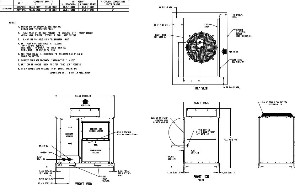
MOUNTING UNIT — When unit is in proper location, use of mounting holes in base rails is recommended for securing unit to supporting structure, or for mounting unit on vibration isolators if required. See Fig. 4. Fasteners for mounting unit are field supplied. Be sure unit is level to within 1/8 in. per foot for proper oil return to compressor.
Step 2 — Check Compressor Mounting — As shipped, units with single compressors are held down with 4 bolts through rubber grommets. All units with tandem compresors are held down with 6 bolts per pair through grommets. After unit is installed, verify mounting bolt torque 7 to10 ft-lb.
Step 3 — Cooler Fluid and Drain Piping Connections
ALL UNITS — These chillers are supplied with factoryinstalled strainer (including blow-down valve) in the entering fluid piping and flow switch in the leaving fluid piping. Flow switch wiring is factory installed. .
 CAUTION
Do not circulate water through unit without strainer in place. Failure to use the strainer represents abuse and may impair or otherwise negatively affect the Carrier product warranty.
Piping connections are located on the front of the chiller when facing the control panel for sizes 010 to 030 and at the
a30-4916
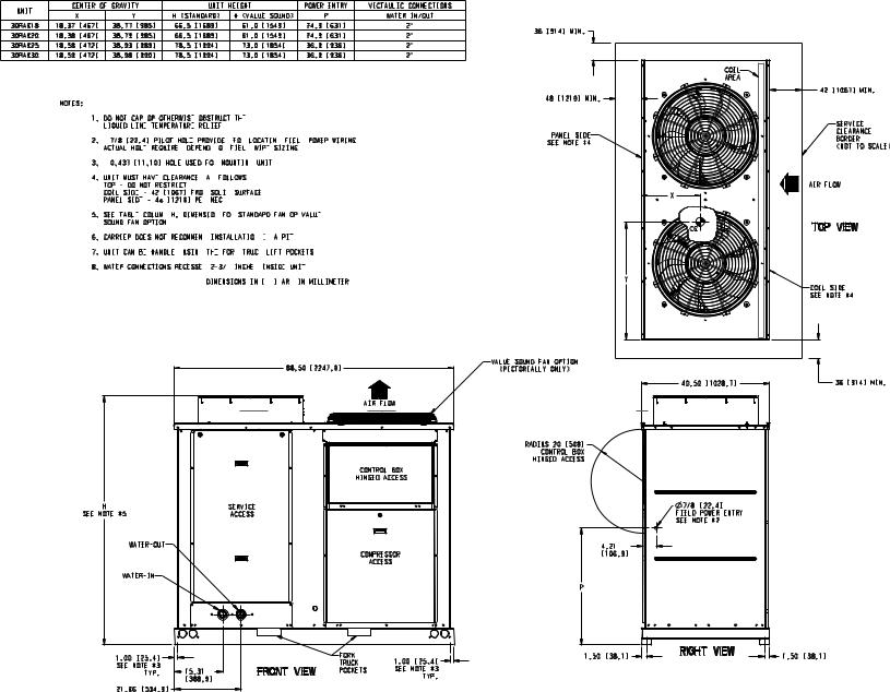
end opposite the control panel for sizes 035 to 060. See Fig. 5-10, depending on model.
All sizes have victaulic connections as shown in the physical data tables. Provide a means of venting air from the high point of the field-installed piping as required. Install field-sup- plied drains in both the entering and leaving fluid connections.
After field piping is complete, freeze-up protection is recommended using inhibited ethylene glycol or other suitable inhibited antifreeze solution and electric heat tapes in areas where piping is exposed to low ambient temperatures (34 F [1 °C] or below). Heat tapes should possess a rating for area ambients and be covered with a suitable thickness of closedcell insulation. Route power for heating tapes from a separately fused disconnect. Identify disconnect as heat tape power source with a warning that power must not be turned off except when unit is being serviced.
The water connections are copper victaulic. Any connecting pipe to the 30RAP pump package must be of a material that will not cause any galvanic corrosion. For this reason, galvanized steel pipe or other dissimilar metals must not be used unless joined by a dielectric coupling.
Installation of water systems should follow sound engineering practice as well as applicable local and industry standards. Improperly designed or installed systems may cause unsatisfactory operation and/or system failure. Consult a water treatment specialist or appropriate literature for information regarding filtration, water treatment, and control devices.
Fig. 4 — Unit Rigging Label Detail
6
7
UNIT |
CENTER OF GRAVITY |
|
UNIT HEIGHT |
|
VICTAULIC CONNECTIONS |
||||
|
X |
|
Y |
H (STANDARD) |
H (VALUE SOUND) |
WATER IN/OUT |
|||
|
|
|
|||||||
30RA010 |
18.40 |
[467] |
37.80 |
[960] |
66.5 |
[1689] |
61.0 |
[1549] |
2" |
STANDARD |
18.35 |
[466] |
37.69 |
[957] |
66.5 |
[1689] |
61.0 |
[1549] |
2" |
30RA015 |
|||||||||
NOTES:
1.DO NOT CAP OR OTHERWISE OBSTRUCT THE
 LIQUID LINE TEMPERATURE RELIEF.
2. 7/8 [22.4] PILOT HOLE PROVIDED
 FOR
FOR LOCATING
 FIELD
FIELD  POWER
POWER  WIRING.
  ACTUAL HOLE REQUIRED
 DEPENDS
 ON
ON FIELD
FIELD WIRE
WIRE
 SIZING.
3.  0.437 [11.10] HOLE USED FOR
 MOUNTING
 UNIT.
UNIT. 
4.UNIT MUST HAVE CLEARANCES AS
AS FOLLOWS:
TOP - DO NOT RESTRICT.
COIL SIDE - 42 [1067] FROM SOLID
SOLID SURFACE.
PANEL SIDE - 48 [1219] PER NEC.
NEC. 
5.SEE TABLE COLUMN H;
H; DIMENSION
 FOR
FOR STANDARD
 FAN OR VALUE
 SOUND FAN OPTION.
6.CARRIER DOES NOT RECOMMEND
 INSTALLATION
  IN
IN
 A PIT.

7. UNIT CAN BE HANDLED USING
USING THE
THE
 FORK
FORK 
 TRUCK
TRUCK 
 LIFT POCKETS.
8. WATER CONNECTIONS RECESSED
 2-3/8
2-3/8 INCHES
 INSIDE UNIT.

9. DIMENSIONS ARE IN INCHES. DIMENSIONS IN [ ] ARE IN MILLIMETERS
66.50 [1689.1]
AIR FLOW
CONTROL BOX
HINGED ACCESS
SERVICE
ACCESS
WATER-OUT

COMPRESSOR
WATER-IN |
ACCESS |
9.52 [241.8] 
FIELD CONTROL WIRING CONNECTIONS
|
1.00 |
[25.4] |
1.00 |
[25.4] |
4948-a30 |
SEE NOTE #3 |
SEE NOTE #3 |
||
|
TYP. |
TYP. |
|
|
|
|
|
FORK |
|
|
9.68 |
[245.9] |
TRUCK |
|
|
|
|
POCKETS |
|
|
15.43 |
[391.9] |
FRONT VIEW |
|
|
|
|
|
|
36 [914] MIN. |
|
|
|
|
|
|
42 [1067] |
|
|
|
MIN. |
48 [1219] MIN. |
|
COIL |
|
|
|
AREA |
|
|
|
|
SERVICE |
|
|
|
CLEARANCE |
PANEL SIDE |
|
|
BORDER |
|
|
(NOT TO SCALE) |
|
SEE NOTE #4 |
|
|
|
|
|
|
|
|
|
CG |
|
|
|
|
AIR FLOW |
|
Y |
|
COIL SIDE |
|
|
|
|
|
|
|
SEE NOTE #4 |
|
|
X |
|
|
|
TOP VIEW |
36 [914] MIN. |
|
|
|
 40.50 [1028.7]

RADIUS 20 [508]

CONTROL BOX
HINGED ACCESS

 7/8 [22.4]
FIELD POWER ENTRY
ENTRY
SEE NOTE #2
H

SEE NOTE #5
 4.61 [117.1]
24.85
[631.2]
1.50 |
[38.1] |
1.50 |
[38.1] |
RIGHT  SIDE
SIDE
VIEW
Fig. 5 — Dimensions — 30RAP010 and 015 Units
VALUE SOUND FAN OPTION
(PICTORIALLY)
8
UNIT |
CENTER OF GRAVITY |
|
UNIT HEIGHT |
|
POWER ENTRY |
VICTAULIC CONNECTIONS |
|||||
|
X |
|
Y |
H (STANDARD) |
H (VALUE SOUND) |
|
P |
WATER IN/OUT |
|||
|
|
|
|
||||||||
30RA018 |
18.37 |
[467] |
38.77 |
[985] |
66.5 |
[1689] |
61.0 |
[1549] |
24.9 |
[631] |
2" |
30RA020 |
18.38 |
[467] |
38.79 |
[985] |
66.5 |
[1689] |
61.0 |
[1549] |
24.9 |
[631] |
2" |
30RA025 |
18.58 |
[472] |
38.93 |
[989] |
78.5 |
[1994] |
73.0 |
[1854] |
36.9 |
[936] |
2" |
30RA030 |
18.59 |
[472] |
38.98 |
[990] |
78.5 |
[1994] |
73.0 |
[1854] |
36.9 |
[936] |
2" |
NOTES:
1.DO NOT CAP OR OTHERWISE
 OBSTRUCT THE
 LIQUID LINE
 TEMPERATURE
 RELIEF.
2. 7/8 [22.4] PILOT HOLE
 PROVIDED
 FOR
FOR LOCATING
 FIELD
FIELD  POWER
POWER  WIRING.
  ACTUAL HOLE
 REQUIRED
 DEPENDS
 ON
ON FIELD
FIELD WIRE
WIRE
 SIZING.
3.  0.437 [11.10] HOLE USED FOR
 MOUNTING
 UNIT.
UNIT. 
4.UNIT MUST HAVE CLEARANCES
 AS
AS FOLLOWS:
TOP - DO NOT RESTRICT.
COIL SIDE - 42 [1067] FROM
 SOLID
SOLID SURFACE.
  PANEL SIDE
 - 48
- 48 [1219] PER
 NEC.
NEC. 
5.SEE TABLE COLUMN
 H;
H; DIMENSION
 FOR
FOR STANDARD
 FAN OR VALUE
 SOUND FAN OPTION.
6.CARRIER DOES NOT RECOMMEND
 INSTALLATION
  IN
IN
 A PIT.

7.UNIT CAN BE HANDLED
 USING
USING THE
THE
 FORK
FORK 
 TRUCK
TRUCK 
 LIFT POCKETS.
8.WATER CONNECTIONS RECESSED
 2-3/8
2-3/8 INCHES
 INSIDE
  UNIT.
UNIT.

9.DIMENSIONS ARE IN INCHES. DIMENSIONS IN [ ] ARE IN MILLIMETERS
|
|
|
88.50 |
[2247.9] |
|
|
|
||
|
|
|
|
|
|
AIR FLOW |
|
||
|
|
|
|
|
|
CONTROL BOX |
|
||
|
|
|
|
|
HINGED ACCESS |
|
|||
H |
|
|
SERVICE |
|
|
|
|
|
|
SEE NOTE #5 |
|
|
ACCESS |
|
|
|
|
|
|
WATER-OUT |
|
|
|
|
|
|
|
||
|
|
|
|
|
|
COMPRESSOR |
|
||
|
|
|
|
|
|
|
ACCESS |
|
|
WATER-IN |
|
|
|
|
|
|
|
||
1.00 |
[25.4] |
|
|
|
FORK |
|
1.00 |
[25.4] |
|
|
|
|
TRUCK |
|
|||||
SEE NOTE #3 |
|
|
|
|
|||||
15.31 |
FRONT VIEW |
POCKETS |
SEE NOTE #3 |
||||||
|
TYP. |
||||||||
|
|
TYP. |
|||||||
|
|
[388.9] |
|
|
|
|
|
||
|
|
|
|
|
|
|
|
||
21.06 |
[534.9] |
|
|
|
|
|
|
|
|
36 [914] MIN. |
|
|
|
|
|
|
COIL |
|
|
|
|
AREA |
|
|
|
|
|
|
42 [1067] MIN. |
48 [1219] MIN. |
|
|
|
|
|
|
|
|
SERVICE |
PANEL SIDE |
|
|
|
CLEARANCE |
|
|
|
BORDER |
|
SEE NOTE #4 |
|
|
|
|
|
|
|
(NOT TO SCALE) |
|
|
|
|
|
|
|
|
|
|
AIR FLOW |
|
X |
|
|
|
|
CG |
|
|
TOP VIEW |
|
Y |
|
|
|
|
|
|
|
COIL SIDE |
|
|
|
|
SEE NOTE #4 |
VALUE SOUND FAN OPTION |
|
|
|
|
(PICTORIALLY ONLY) |
|
|
|
|
|
40.50 [1028.7] |
|
36 [914] MIN. |
|
RADIUS 20 [508] |
|
|
|
|
CONTROL BOX |
|
|
|
|
HINGED ACCESS |
|
|
|
|
|
7/8 |
[22.4] |
|
|
|
FIELD POWER ENTRY |
|
|
|
|
SEE NOTE #2 |
|
|
|
|
4.21 |
|
|
|
|
[106.9] |
|
|
|
P |
|
|
|
|
1.50 |
RIGHT VIEW |
1.50 |
[38.1] |
|
[38.1] |
|
|||
Fig. 6 — Dimensions — 30RAP018-030 Units
4949-a30

UNIT |
CENTER OF GRAVITY |
UNIT HEIGHT |
|
VICTAULIC CONNECTIONS |
|
|
|
|
|
|
|
|
|
|
|||
X |
Y |
H (STANDARD) |
H (VALUE SOUND) |
WATER IN/OUT |
|
|
|
|
|
|
|
|
|
|
|||
|
|
|
|
|
|
|
|
|
|
|
|||||||
30RA035 |
36.45 [926] |
46.08 [1170] |
66.5 [1689] |
61.0 [1549] |
|
2-1/2" |
|
|
|
|
|
|
|
|
|
|
|
30RA040 |
36.24 [921] |
44.03 [1118] |
66.5 [1689] |
61.0 [1549] |
|
2-1/2" |
|
|
|
|
|
|
|
|
|
|
|
30RA045 |
36.24 [921] |
46.15 [1172] |
78.5 [1994] |
73.0 [1854] |
|
2-1/2" |
|
|
AIR FLOW |
|
|
|
|
|
|
|
|
|
|
|
|
|
|
|
|
|
|
COIL SIDE |
|
|
|
|
|
|
|
30RA050 |
36.00 [914] |
44.00 [1118] |
78.5 [1994] |
73.0 [1854] |
|
2-1/2" |
|
|
|
|
|
42 [1067] MIN. |
|
|
|
||
30RA055 |
36.48 [927] |
44.60 [1133] |
78.5 [1994] |
73.0 [1854] |
|
2-1/2" |
|
|
|
SEE NOTE #4 |
|
|
|
|
|
|
|
|
|
|
|
|
|
|
|
|
|
|
|||||||
30RA060 |
36.50 [927] |
44.56 [1132] |
78.5 [1994] |
73.0 [1854] |
|
2-1/2" |
|
|
|
|
|
|
|
|
|
|
|
|
|
|
|
|
|
|
|
|
|
|
COIL |
|
|
NOTE: 3 OR 4 FANS |
|
|
|
|
|
|
|
|
|
|
|
|
|
|
AREA |
|
|
|
|
|
|
|
NOTES: |
|
|
|
|
|
48 [1219] MIN. |
|
|
|
|
|
|
|
|
|
|
|
|
|
|
|
|
|
|
|
|
|
|
|
|
|
|
|
|
|
1. DO NOT CAP OR OTHERWISE OBSTRUCT THE |
|
|
|
|
|
|
|
|
|
SERVICE |
|
|
|
|||
|
LIQUID LINE TEMPERATURE RELIEF. |
|
|
|
|
|
|
|
|
|
|
|
|
|
|||
|
|
|
|
|
|
|
|
|
|
|
|
|
|
CLEARANCE |
|
|
|
|
2. 7/8 [22.4] PILOT HOLE PROVIDED FOR LOCATING FIELD POWER WIRING. |
|
|
|
|
|
|
BORDER |
|
|
|
||||||
|
ACTUAL HOLE REQUIRED DEPENDS ON FIELD WIRE SIZING. |
|
|
|
|
|
|
|
(NOT TO SCALE) |
|
|
||||||
|
3. 0.437 [11.10] HOLE USED FOR MOUNTING UNIT. |
|
|
|
|
|
|
|
|
|
|
|
|
||||
|
4. UNIT MUST HAVE CLEARANCES AS FOLLOWS: |
|
|
PANEL SIDE |
|
|
CG |
|
|
|
|
|
|
|
|||
|
TOP - DO NOT RESTRICT. |
|
|
|
|
|
|
|
|
|
|
|
|
|
|||
|
COIL SIDE - 42 [1067] FROM SOLID SURFACE. |
|
|
SEE NOTE #4 |
|
|
|
|
|
|
|
|
|
|
|||
|
PANEL SIDE - 48 [1219] PER NEC. |
|
|
|
|
|
|
|
|
|
|
PANEL SIDE |
|
|
|
||
|
|
|
|
|
|
|
|
|
|
|
|
|
|
|
|
|
|
|
5. SEE TABLE COLUMN H; DIMENSION FOR STANDARD FAN OR VALUE |
|
|
|
|
|
|
SEE NOTE #4 |
|
|
|
||||||
|
|
|
|
|
|
|
|
|
|
|
|||||||
|
SOUND FAN OPTION. |
|
|
|
|
|
|
|
|
|
|
|
|
|
|
||
|
6. CARRIER DOES NOT RECOMMEND INSTALLATION IN A PIT. |
|
|
|
|
|
|
|
|
|
|
|
|||||
|
7. UNIT CAN BE HANDLED USING THE FORK TRUCK LIFT POCKETS |
|
Y |
|
|
|
|
|
|
|
|
||||||
|
|
|
|
|
|
|
|
|
|
|
|||||||
|
(MINIMUM OF 60" FORK LENGTH). |
|
|
|
|
|
|
|
|
|
|
48 [1219] MIN. |
|
|
|
||
|
|
|
|
|
|
|
|
|
|
|
|
|
|
|
|
|
|
|
8. WATER CONNECTIONS RECESSED 4-1/2 INCHES INSIDE UNIT. |
|
|
|
|
COIL |
|
|
|
|
|
|
|||||
|
9. DIMENSIONS ARE IN INCHES. DIMENSIONS IN [ |
|
|
|
|
|
AREA |
|
|
|
|
|
|
||||
|
] ARE IN MILLIMETERS |
|
|
|
|
|
|
|
|
|
|
||||||
9 |
|
|
|
|
|
|
|
|
|
X |
TOP VIEW |
COIL SIDE |
|
42 [1067] MIN. |
|
|
|
|
|
|
|
|
|
|
|
|
|
|
|
|
|
||||
|
|
|
|
|
|
|
|
|
|
|
|
|
|
|
|||
|
|
|
|
|
|
|
|
|
|
|
SEE NOTE #4 |
|
|
|
|
||
|
|
|
|
|
|
|
|
|
|
|
|
|
|
|
|
|
|
|
|
|
88.50 [2247.9] |
|
|
|
|
|
|
|
|
|
|
|
|
|
|
|
|
|
|
|
|
|
|
|
|
92.50 |
[2349.5] |
|
VALUE SOUND FAN OPTION |
|
|
|
|
|
|
|
|
|
|
|
|
|
|
|
|
|
|
|
|
||
|
|
AIR FLOW |
|
|
|
|
|
|
|
|
|
(PICTORIALLY ONLY) |
|
|
|
||
|
|
|
|
|
|
|
|
|
|
|
|
|
|
|
|
||
|
|
|
|
|
|
|
|
|
|
|
AIR FLOW |
|
|
|
|
|
|
|
|
|
|
|
|
|
RADIUS |
20 [508] |
|
|
|
|
|
|
|
|
|
|
|
|
|
|
|
|
CONTROL BOX |
|
|
|
|
|
|
|
|
||
|
|
|
|
|
|
|
HINGED ACCESS |
|
|
|
|
|
|
|
|
||
|
FIELD |
|
|
|
|
|
|
|
|
|
|
|
|
|
|
|
|
|
CONTROL |
|
CONTROL BOX |
|
|
|
|
|
|
|
|
|
|
|
|
|
|
|
WIRING |
|
|
|
|
|
|
|
|
|
|
|
|
|
|
||
CONNECTIONS |
|
HINGED ACCESS |
|
|
H |
|
|
|
|
|
|
|
|
WATER-IN |
|
||
|
|
|
|
|
|
|
|
|
|
|
|
|
|
|
|
||
|
|
|
|
|
|
|
SEE NOTE #5 |
|
|
|
|
|
|
|
|
|
|
|
|
|
|
|
|
|
|
|
|
|
|
|
|
|
|
|
|
|
|
|
|
|
|
|
|
|
|
7/8 [22.4] |
|
|
|
|
|
|
|
|
|
|
|
|
|
|
|
|
|
FIELD POWER ENTRY |
|
|
|
|
|
|
|
|
|
|
|
|
|
|
|
|
|
SEE NOTE #2 |
|
|
|
|
|
|
|
|
|
CIRCUIT A |
|
CIRCUIT B |
|
|
|
|
|
|
31.74 |
|
WATER-OUT |
|
|||
|
|
COMPRESSOR |
|
|
|
|
|
|
|
[806.2] |
|
|
|
||||
|
|
|
COMPRESSOR |
|
|
|
|
|
|
|
|
|
|||||
|
|
ACCESS |
|
|
27.98 |
|
|
|
|
|
|
|
|
|
|
||
|
|
|
|
|
ACCESS |
|
4.63 |
|
|
|
|
|
|
|
|
||
|
|
|
|
|
|
|
[710.7] |
|
|
|
|
|
|
|
|
||
|
|
|
|
|
|
|
[117.6] |
|
|
|
|
|
|
|
|
||
|
|
|
|
|
|
|
|
|
|
|
|
|
|
|
|
|
|
|
|
|
|
|
|
|
|
|
|
|
|
|
|
11.20 |
|
|
|
|
|
|
|
|
|
|
|
|
|
|
|
|
|
[284.5] |
|
|
|
|
|
|
|
|
FORK |
|
|
1.50 |
RIGHT VIEW |
1.50 |
|
|
|
1.00 |
[25.4] |
||
|
|
|
|
|
|
|
[38.1] |
|
|
|
|||||||
4950-a30 |
|
|
|
|
|
[38.1] |
1.00 |
[25.4] |
|
||||||||
|
|
|
TRUCK |
|
|
|
SEE NOTE #3 |
||||||||||
|
|
|
FRONT VIEW |
POCKETS |
|
|
|
|
|
|
SEE NOTE #3 |
44.00 |
|
TYP. |
|||
|
|
|
|
|
|
|
|
|
|
|
|
|
|
TYP. |
[1117.6] |
|
|
|
|
|
|
|
|
|
|
|
|
|
|
|
|
|
|
REAR VIEW |
|
Fig. 7 — Dimensions — 30RAP035-060 Units
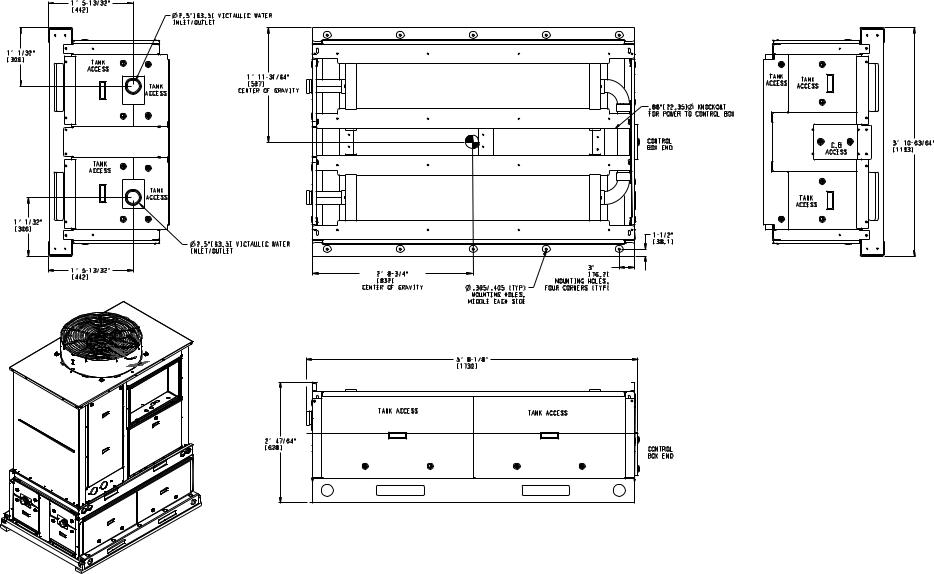
|
1' 5-13/32" |
|
|
|
|
|
[442] |
2.5"[63.5] VICTAULIC WATER |
|
|
|
|
|
|
|
|
|
|
|
INLET/OUTLET |
|
|
|
1' 1/32" |
|
|
|
|
|
[306] |
TANK |
|
|
|
|
|
|
|
|
|
|
|
ACCESS |
|
|
|
|
|
|
1' 11-31/64" |
|
|
|
|
TANK |
[597] |
|
|
|
|
CENTER OF GRAVITY |
|
|
|
|
|
ACCESS |
|
|
|
|
|
|
|
|
|
|
|
|
|
|
.88"[22.35] |
KNOCKOUT |
|
|
|
|
FOR POWER TO CONTROL BOX |
|
|
|
|
|
CONTROL |
|
|
|
|
|
BOX END |
|
|
TANK |
|
|
|
|
|
ACCESS |
|
|
|
|
|
TANK |
|
|
|
|
|
ACCESS |
|
|
|
|
1' |
1/32" |
|
|
|
|
[306] |
|
|
1-1/2" |
|
|
|
|
|
|
|
|
|
|
2.5"[63.5] VICTAULIC WATER |
|
[38.1] |
|
|
|
|
|
|
|
|
|
INLET/OUTLET |
|
|
|
|
1' 5-13/32" |
|
|
3" |
|
|
2' 8-3/4" |
|
[76.2] |
|
|
|
[442] |
|
|
||
|
[832] |
|
MOUNTING HOLES, |
|
|
|
|
|
|
||
|
|
CENTER OF GRAVITY |
.395/.405 (TYP) |
FOUR CORNERS (TYP) |
|
10 |
|
|
MOUNTING HOLES, |
|
|
|
|
MIDDLE EACH SIDE |
|
|
|
|
|
|
|
|
|
|
|
|
5' 8-1/8" |
|
|
|
|
|
[1730] |
|
|
|
|
TANK ACCESS |
|
TANK ACCESS |
|
|
|
|
|
|
|
|
|
2' 47/64" |
|
|
|
|
|
[628] |
|
CONTROL |
|
|
|
|
|
BOX END |
|
4879-a30
TANK |
TANK |
|
ACCESS |
||
ACCESS |
||
|
||
|
C.B |
|
|
ACCESS |
|
|
TANK |
|
|
ACCESS |
3' 10-63/64" [1193]
Fig. 8 — Accessory Storage Tank Dimensions — 30RAP010,015 Units
|
|
1' 5-13/32" |
|
|
|
|
|
[442] |
2.5"[63.5] VICTAULIC WATER |
|
|
|
|
|
|
|
|
|
|
|
INLET/OUTLET |
|
|
1' 1/64" |
|
|
|
|
|
[305] |
TANK |
|
|
|
|
|
|
|
|
|
|
|
|
ACCESS |
|
|
|
|
|
|
1' 11-17/32" |
|
|
|
|
TANK |
[598] |
|
|
|
|
ACCESS |
CENTER OF GRAVITY |
|
|
|
|
TANK |
|
|
|
|
|
ACCESS |
|
|
|
|
|
TANK |
|
|
|
|
|
ACCESS |
|
|
|
1' |
1/32" |
|
|
|
|
[306] |
|
|
|
|
|
|
|
|
2.5"[63.5] VICTAULIC WATER |
|
|
|
|
INLET/OUTLET |
|
|
|
|
|
1' 5-13/32" |
3' 8" |
.395/.405 (TYP) |
3" |
|
|
[1118] |
MOUNTING HOLES, |
[76.2] |
|
|
|
[442] |
|||
|
|
CENTER OF GRAVITY |
MIDDLE EACH SIDE |
MOUNTING HOLES, |
|
|
|
|
|||
.88" (22.35) KNOCKOUT FOR
POWER TO THE CONTROL BOX
BOX
TANK |
TANK |
|
ACCESS |
ACCESS |
|
CONTROL |
C.B |
|
BOX END |
||
ACCESS |
||
|
||
|
TANK |
|
|
ACCESS |
|
1-1/2" |
|
|
[38.1] |
|
|
|
|
FOUR CORNERS (TYP) |
11 |
|
|
|
|
|
7' 5-7/8" |
|
|
|
[2283] |
|
|
TANK ACCESS |
TANK ACCESS |
TANK ACCESS |
2' |
47/64" |
|
|
[628] |
|
CONTROL |
|
|
|
|
|
|
|
|
BOX END |
3' 10-63/64" [1193]
4880-a30
Fig. 9 — Accessory Storage Tank Dimensions — 30RAP018-030 Units
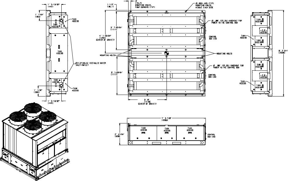
|
|
3" |
|
|
|
|
1' 5-13/32" |
1-1/2" |
[76.2] |
|
|
.395/.405 (TYP) |
|
MOUNTING HOLES, |
|
MOUNTING HOLES, |
|
|||
[442] |
[38.1] |
|
|
|||
FOUR CORNERS (TYP) |
|
MIDDLE EACH SIDE |
|
|||
|
|
|
|
|||
1' 1/64" |
|
|
|
|
|
|
[305] |
|
|
|
|
|
|
|
TANK |
|
|
|
.88" (22.35) KNOCKOUT FOR |
|
|
ACCESS |
|
|
|
||
|
|
|
|
POWER TO THE CONTROL BOX |
|
|
TANK |
|
|
|
|
|
|
|
|
|
|
|
|
|
ACCESS |
3' 7-63/64" |
|
|
|
|
|
|
|
|
|
|
|
|
|
[1117] |
|
|
|
|
|
|
4' 1-23/64" |
|
|
|
CONTROL |
TANK |
|
[1254] |
|
|
|
ACCESS |
|
|
|
|
|
BOX END |
||
|
CENTER OF GRAVITY |
|
|
|
|
|
|
|
|
|
|
|
|
TANK |
|
|
|
|
|
|
ACCESS |
MOUNTING HOLES |
|
|
|
MOUNTING HOLES |
|
|
|
|
|
|
|
|
|
2.5"[63.5] VICTAULIC WATER |
|
|
|
|
|
|
INLET/OUTLET |
|
|
|
.88" (22.35) KNOCKOUT FOR |
|
|
|
|
|
|
POWER TO THE CONTROL BOX |
|
|
3' 7-63/64" |
|
|
|
|
|
|
[1117] |
|
|
|
CONTROL |
|
|
|
|
|
|
BOX END |
|
TANK |
|
|
|
|
|
TANK |
ACCESS |
|
|
|
|
|
|
|
|
|
|
|
ACCESS |
|
|
|
|
|
|
|
|
1' 1/32" |
TANK |
|
|
|
|
|
ACCESS |
|
|
|
|
|
|
[306] |
|
|
|
|
|
|
12 |
|
3' |
8" |
|
|
|
1' 5-13/32" |
|
|
|
|
||
|
[1118] |
|
|
|
||
[442] |
|
|
|
|
||
|
CENTER OF GRAVITY |
|
|
|
||
|
|
|
|
|
||
|
|
|
|
7' 5-7/8" |
|
|
|
|
|
|
[2283] |
|
|
|
|
TANK |
|
TANK |
TANK |
|
|
|
ACCESS |
|
ACCESS |
|
|
|
|
|
ACCESS |
|
||
|
|
|
|
|
|
|
|
2' 47/64" |
|
|
|
CONTROL |
|
|
[628] |
|
|
|
BOX END |
|
TANK |
ACCESS |
 C.B
C.B 
 ACCESS

TANK |
ACCESS |
TANK |
ACCESS |
 C.B
C.B 
 ACCESS

TANK |
ACCESS |
4881-a30


 4880-a30
8' 2-3/4" [2508]
Fig. 10 — Accessory Storage Tank Dimensions — 30RAP035-060 Units
 Loading...