


 Loading...
AquaEdge™
19XR
Two-Stage Semi-Hermetic Centrifugal Liquid Chillers
with PIC 5 Controls and HFC-134a
50/60 Hz
Start-Up, Operation, and Maintenance Instructions
SAFETY CONSIDERATIONS
Centrifugal liquid chillers are designed to provide safe and reliable service when operated within design specifications. When operating this equipment, use good judgment and safety precautions to avoid damage to equipment and property or injury to personnel.
Be sure you understand and follow the procedures and safety precautions contained in the chiller instructions as well as those listed in this guide.
DANGER
Failure to follow these procedures will result in severe personal injury or death.
DO NOT VENT refrigerant relief valves within a building. Outlet from rupture disc or relief valve must be vented outdoors in accordance with the latest edition of ANSI/ ASHRAE 15 (American National Standards Institute/ American Society of Heating, Refrigerating, and AirConditioning Engineers). The accumulation of refrigerant in an enclosed space can displace oxygen and cause asphyxiation.
PROVIDE adequate ventilation in accordance with ANSI/ ASHRAE 15, especially for enclosed and low overhead spaces. Inhalation of high concentrations of vapor is harmful and may cause heart irregularities, unconsciousness, or death. Misuse can be fatal. Vapor is heavier than air and reduces the amount of oxygen available for breathing. Product causes eye and skin irritation. Decomposition products are hazardous.
DO NOT USE OXYGEN to purge lines or to pressurize a chiller for any purpose. Oxygen gas reacts violently with oil, grease, and other common substances.
NEVER EXCEED specified test pressures; VERIFY the allowable test pressure by checking the instruction literature and the design pressures on the equipment nameplate.
DO NOT USE air for leak testing. Use only refrigerant or dry nitrogen.
DO NOT VALVE OFF any safety device.
BE SURE that all pressure relief devices are properly installed and functioning before operating any chiller.
RISK OF INJURY OR DEATH by electrocution. High voltage is present on motor leads even though the motor is not running when a solid-state or wye-delta mechanical starter is used. Open the power supply disconnect before touching motor leads or terminals.
 WARNING
Failure to follow these procedures may result in personal injury or death.
DO NOT USE TORCH to remove any component. System contains oil and refrigerant under pressure.
To remove a component, wear protective gloves and goggles and proceed as follows:
a.Shut off electrical power to unit.
b.Recover refrigerant to relieve all pressure from system using both high-pressure and low pressure ports.
c.Traces of vapor should be displaced with nitrogen and the work area should be well ventilated. Refrigerant in contact with an open flame produces toxic gases.
d.Cut component connection tubing with tubing cutter and remove component from unit. Use a pan to catch any oil that may come out of the lines and as a gage for how much oil to add to the system.
e.Carefully unsweat remaining tubing stubs when necessary. Oil can ignite when exposed to torch flame.
DO NOT USE eyebolts or eyebolt holes to rig chiller sections or the entire assembly.
DO NOT work on high-voltage equipment unless you are a qualified electrician.
DO NOT WORK ON electrical components, including control panels, switches, starters, or oil heater until you are sure ALL POWER IS OFF and no residual voltage can leak from capacitors or solid-state components.
LOCK OPEN AND TAG electrical circuits during servicing. IF WORK IS INTERRUPTED, confirm that all circuits are deenergized before resuming work.
AVOID SPILLING liquid refrigerant on skin or getting it into the eyes. USE SAFETY GOGGLES. Wash any spills from the skin with soap and water. If liquid refrigerant enters the eyes, IMMEDIATELY FLUSH EYES with water and consult a physician.
NEVER APPLY an open flame or live steam to a refrigerant cylinder. Dangerous over pressure can result. When it is necessary to heat refrigerant, use only warm (110 F [43 C]) water.
DO NOT REUSE disposable (nonreturnable) cylinders or attempt to refill them. It is DANGEROUS AND ILLEGAL. When cylinder is emptied, evacuate remaining gas pressure, loosen the collar and unscrew and discard the valve stem. DO NOT INCINERATE.
CHECK THE REFRIGERANT TYPE before adding refrigerant to the chiller. The introduction of the wrong refrigerant can cause damage or malfunction to this chiller.
(Warnings continued on next page.)
Manufacturer reserves the right to discontinue, or change at any time, specifications or designs without notice and without incurring obligations.
Catalog No. 04-53190038-01 |
Printed in U.S.A. |
Form 19XR-CLT-12SS |
Pg 1 |
12-15 |
Replaces: 19XR-CLT-11SS |

WARNING 
Operation of this equipment with refrigerants other than those cited herein should comply with ANSI/ASHRAE 15 (latest edition). Contact Carrier for further information on use of this chiller with other refrigerants.
DO NOT ATTEMPT TO REMOVE fittings, covers, etc., while chiller is under pressure or while chiller is running. Be sure pressure is at 0 psig (0 kPa) before breaking any refrigerant connection.
CAREFULLY INSPECT all relief valves, rupture discs, and other relief devices AT LEAST ONCE A YEAR. If chiller operates in a corrosive atmosphere, inspect the devices at more frequent intervals.
DO NOT ATTEMPT TO REPAIR OR RECONDITION any relief device when corrosion or build-up of foreign material (rust, dirt, scale, etc.) is found within the valve body or mechanism. Replace the device.
DO NOT install relief devices in series or backwards.
USE CARE when working near or in line with a compressed spring. Sudden release of the spring can cause it and objects in its path to act as projectiles.
CAUTION
Failure to follow these procedures may result in personal injury or damage to equipment.
DO NOT STEP on refrigerant lines. Broken lines can whip about and release refrigerant, causing personal injury.
DO NOT climb over a chiller. Use platform, catwalk, or staging. Follow safe practices when using ladders.
USE MECHANICAL EQUIPMENT (crane, hoist, etc.) to lift or move inspection covers or other heavy components. Even if components are light, use mechanical equipment when there is a risk of slipping or losing your balance.
BE AWARE that certain automatic start arrangements CAN ENGAGE THE STARTER, TOWER FAN, OR PUMPS. Open the disconnect ahead of the starter, tower fans, or pumps.
USE only repair or replacement parts that meet the code requirements of the original equipment.
DO NOT VENT OR DRAIN waterboxes containing industrial brines, liquid, gases, or semisolids without the permission of your process control group.
DO NOT LOOSEN waterbox cover bolts until the waterbox has been completely drained.
DO NOT LOOSEN a packing gland nut before checking that the nut has a positive thread engagement.
PERIODICALLY INSPECT all valves, fittings, and piping for corrosion, rust, leaks, or damage.
PROVIDE A DRAIN connection in the vent line near each pressure relief device to prevent a build-up of condensate or rain water.
DO NOT re-use compressor oil or any oil that has been exposed to the atmosphere. Dispose of oil per local codes and regulations.
DO NOT leave refrigerant system open to air any longer than the actual time required to service the equipment. Seal circuits being serviced and charge with dry nitrogen to prevent oil contamination when timely repairs cannot be completed.
CONTENTS
Page
SAFETY CONSIDERATIONS . . . . . . . . . . . . . . . . . . . . . . . 1,2
INTRODUCTION . . . . . . . . . . . . . . . . . . . . . . . . . . . . . . . . . . . . 4
ABBREVIATIONS AND EXPLANATIONS . . . . . . . . . . . . 4
CHILLER FAMILIARIZATION . . . . . . . . . . . . . . . . . . . . . . .4-6
Chiller Information Nameplate . . . . . . . . . . . . . . . . . . . . . . 4
System Components . . . . . . . . . . . . . . . . . . . . . . . . . . . . . . . 4
Cooler . . . . . . . . . . . . . . . . . . . . . . . . . . . . . . . . . . . . . . . . . . . . . . 4
Condenser. . . . . . . . . . . . . . . . . . . . . . . . . . . . . . . . . . . . . . . . . . 4
Motor-Compressor . . . . . . . . . . . . . . . . . . . . . . . . . . . . . . . . . 4
Control Panel . . . . . . . . . . . . . . . . . . . . . . . . . . . . . . . . . . . . . . . 4
Economizer. . . . . . . . . . . . . . . . . . . . . . . . . . . . . . . . . . . . . . . . . 5
Free-Standing Starter . . . . . . . . . . . . . . . . . . . . . . . . . . . . . . . 5
REFRIGERATION CYCLE . . . . . . . . . . . . . . . . . . . . . . . . . . . 7
MOTOR AND OIL COOLING CYCLE. . . . . . . . . . . . . . . . . 8
LUBRICATION CYCLE . . . . . . . . . . . . . . . . . . . . . . . . . . . . . 8,9
Summary . . . . . . . . . . . . . . . . . . . . . . . . . . . . . . . . . . . . . . . . . 8
Details . . . . . . . . . . . . . . . . . . . . . . . . . . . . . . . . . . . . . . . . . . . . 8
Bearings . . . . . . . . . . . . . . . . . . . . . . . . . . . . . . . . . . . . . . . . . . 8
Oil Reclaim System . . . . . . . . . . . . . . . . . . . . . . . . . . . . . . . 8
•PRIMARY OIL RECOVERY MODE
•SECONDARY OIL RECOVERY METHOD
STARTING EQUIPMENT . . . . . . . . . . . . . . . . . . . . . . . . . . 10
Solid-State Starter (Optional) . . . . . . . . . . . . . . . . . . . . . 10
Freestanding Medium Voltage VFD (Optional) . . . . . 10
CONTROLS . . . . . . . . . . . . . . . . . . . . . . . . . . . . . . . . . . . . . . 10
Definitions . . . . . . . . . . . . . . . . . . . . . . . . . . . . . . . . . . . . . . . 10
• |
ANALOG SIGNAL |
|
• |
DISCRETE SIGNAL |
|
General . . . . . . . . . . . . . . . . . . . . . . . . . . . . . . . . . . . . . . . . . . |
10 |
|
PIC 5 System Components . . . . . . . . . . . . . . . . . . . . 10,11
START-UP/SHUTDOWN/RECYCLE
SEQUENCE. . . . . . . . . . . . . . . . . . . . . . . . . . . . . . . . . . . .11,12
Local Start/Stop Control . . . . . . . . . . . . . . . . . . . . . . . . . . . 11
Lubrication Control . . . . . . . . . . . . . . . . . . . . . . . . . . . . . . . . 12
Shutdown . . . . . . . . . . . . . . . . . . . . . . . . . . . . . . . . . . . . . . . . . 12
BEFORE INITIAL START-UP . . . . . . . . . . . . . . . . . . . . .13-28
Job Data Required . . . . . . . . . . . . . . . . . . . . . . . . . . . . . . . . . 13
Equipment Required. . . . . . . . . . . . . . . . . . . . . . . . . . . . . . . 13
Remove Shipping Packaging . . . . . . . . . . . . . . . . . . . . . . 13
Open Oil Circuit Valves . . . . . . . . . . . . . . . . . . . . . . . . . . . . 13
Tighten All Gasketed Joints . . . . . . . . . . . . . . . . . . . . . . . 13
Check Chiller Tightness . . . . . . . . . . . . . . . . . . . . . . . . . . . 13
Refrigerant Tracer . . . . . . . . . . . . . . . . . . . . . . . . . . . . . . . . . 16
Leak Test Chiller. . . . . . . . . . . . . . . . . . . . . . . . . . . . . . . . . . . 16
Standing Vacuum Test. . . . . . . . . . . . . . . . . . . . . . . . . . . . . 16
Chiller Dehydration . . . . . . . . . . . . . . . . . . . . . . . . . . . . . . . . 18
Inspect Water Piping . . . . . . . . . . . . . . . . . . . . . . . . . . . . . . 18
Check Relief Valves . . . . . . . . . . . . . . . . . . . . . . . . . . . . . . . 18
Inspect Wiring . . . . . . . . . . . . . . . . . . . . . . . . . . . . . . . . . . . . . 18
Check Starter . . . . . . . . . . . . . . . . . . . . . . . . . . . . . . . . . . . . 19
• |
MECHANICAL STARTER |
|
• |
SOLID-STATE STARTER |
|
Oil Charge . . . . . . . . . . . . . . . . . . . . . . . . . . . . . . . . . . . . . . . |
19 |
|
Power Up the Controls and
Check the Oil Heater . . . . . . . . . . . . . . . . . . . . . . . . . . . 19
Software Configuration . . . . . . . . . . . . . . . . . . . . . . . . . . . 19
Input the Design Set Points . . . . . . . . . . . . . . . . . . . . . . . 20
Input the Local Occupied Schedule . . . . . . . . . . . . . . . . 20
Input Service Configurations . . . . . . . . . . . . . . . . . . . . . 20
•PASSWORD
•LOGIN/LOGOUT
•INPUT TIME AND DATE
•MODIFY CONTROLLER IDENTIFICATION IF NECESSARY
•CONFIGURE SERVICE TABLES
2
CONTENTS (cont)
Page
Field Set Up and Verification . . . . . . . . . . . . . . . . . . . . . . .22
• LABEL LOCATIONS
• STARTER/DRIVE PROTECTION AND OTHER INCOMING WIRING
• FINE TUNING VPF (VARIABLE PRIMARY FLOW) SURGE PREVENTION
• MODIFY EQUIPMENT CONFIGURATION IF NECESSARY
Perform a Control Test (Quick Test) . . . . . . . . . . . . . . . .24 Charge Refrigerant Into Chiller . . . . . . . . . . . . . . . . . . . 25
•CHILLER EQUALIZATION WITHOUT A PUMPOUT UNIT
•CHILLER EQUALIZATION WITH FREE-STANDING PUMPOUT UNIT
•TRIMMING REFRIGERANT CHARGE
INITIAL START-UP . . . . . . . . . . . . . . . . . . . . . . . . . . . . . |
29,30 |
|
Preparation. . . . . . . . . . . . . . . . . . . . . . . . . . . . . . . . . . . . . . |
. . .29 |
|
Check Motor Rotation . . . . . . . . . . . . . . . . . . . . . . . . . . . |
. . .29 |
|
Check Oil Pressure and Compressor Stop . . . . . . |
. . .29 |
|
To Prevent Accidental Start-Up. . . . . . . . . . . . . . . . . . |
. . .29 |
|
Check Chiller Operating Condition . . . . . . . . . . . . . . |
. . .29 |
|
Instruct the Customer Operator . . . . . . . . . . . . . . . . . |
. . .29 |
|
• |
COOLER-CONDENSER |
|
• OPTIONAL PUMPOUT STORAGE TANK AND |
|
|
|
PUMPOUT SYSTEM |
|
• |
MOTOR COMPRESSOR ASSEMBLY |
|
• |
MOTOR COMPRESSOR LUBRICATION |
|
|
SYSTEM |
|
• |
ECONOMIZER |
|
• |
CONTROL SYSTEM |
|
• |
AUXILIARY EQUIPMENT |
|
• |
DESCRIBE CHILLER CYCLES |
|
• |
REVIEW MAINTENANCE |
|
• SAFETY DEVICES AND PROCEDURES |
|
|
• |
CHECK OPERATOR KNOWLEDGE |
|
• REVIEW THE START-UP, OPERATION, AND |
|
|
|
MAINTENANCE MANUAL |
|
OPERATING INSTRUCTIONS . . . . . . . . . . . . . . . . . . . . 30,31 Operator Duties . . . . . . . . . . . . . . . . . . . . . . . . . . . . . . . . . . . .30
Prepare the Chiller for Start-Up. . . . . . . . . . . . . . . . . . . . .30
To Start the Chiller . . . . . . . . . . . . . . . . . . . . . . . . . . . . . . . . .30 Check the Running System. . . . . . . . . . . . . . . . . . . . . . . . .30 To Stop the Chiller . . . . . . . . . . . . . . . . . . . . . . . . . . . . . . . . .30 After Limited Shutdown . . . . . . . . . . . . . . . . . . . . . . . . . . . .30
Preparation for Extended Shutdown. . . . . . . . . . . . . . . .30
After Extended Shutdown . . . . . . . . . . . . . . . . . . . . . . . . . .30 Cold Weather Operation . . . . . . . . . . . . . . . . . . . . . . . . . . . .31
Manual Guide Vane Operation . . . . . . . . . . . . . . . . . . . . . .31
Refrigeration Log. . . . . . . . . . . . . . . . . . . . . . . . . . . . . . . . . . .31
PUMPOUT AND REFRIGERANT TRANSFER PROCEDURES . . . . . . . . . . . . . . . . . . . . . . . . . . . . . . . . 31-36
Preparation. . . . . . . . . . . . . . . . . . . . . . . . . . . . . . . . . . . . . . . . .31
Operating the Optional Pumpout Unit . . . . . . . . . . . . . .33
• TO READ REFRIGERANT PRESSURES
• POSITIVE PRESSURE CHILLERS WITH STORAGE
TANKS
• CHILLERS WITH ISOLATION VALVES
• DISTILLING THE REFRIGERANT
GENERAL MAINTENANCE . . . . . . . . . . . . . . . . . . . . . . 36-38
Refrigerant Properties . . . . . . . . . . . . . . . . . . . . . . . . . . . . . .36
Adding Refrigerant . . . . . . . . . . . . . . . . . . . . . . . . . . . . . . . . .36
Adjusting the Refrigerant Charge. . . . . . . . . . . . . . . . . . .36
Refrigerant Leak Testing . . . . . . . . . . . . . . . . . . . . . . . . . . .36
Leak Rate . . . . . . . . . . . . . . . . . . . . . . . . . . . . . . . . . . . . . . . . . .36
Page
Test After Service, Repair, or Major Leak. . . . . . . . . . . 36
• TESTING WITH REFRIGERANT TRACER
• TESTING WITHOUT REFRIGERANT TRACER
• TO PRESSURIZE WITH DRY NITROGEN
Repair the Leak, Retest, and Apply
Standing Vacuum Test . . . . . . . . . . . . . . . . . . . . . . . . . . . 36 Checking Guide Vanes . . . . . . . . . . . . . . . . . . . . . . . . . . . . . 36 Trim Refrigerant Charge . . . . . . . . . . . . . . . . . . . . . . . . . . . 38
WEEKLY MAINTENANCE. . . . . . . . . . . . . . . . . . . . . . . . . . . 38
Check the Lubrication System . . . . . . . . . . . . . . . . . . . . . 38
SCHEDULED MAINTENANCE . . . . . . . . . . . . . . . . . . . 38-41
Service Ontime. . . . . . . . . . . . . . . . . . . . . . . . . . . . . . . . . . . . . 38
Inspect the Control Panel . . . . . . . . . . . . . . . . . . . . . . . . . . 38
Changing Oil Filter . . . . . . . . . . . . . . . . . . . . . . . . . . . . . . . . . 39
Oil Specification . . . . . . . . . . . . . . . . . . . . . . . . . . . . . . . . . . . 39
Oil Changes . . . . . . . . . . . . . . . . . . . . . . . . . . . . . . . . . . . . . . . . 39
• TO CHANGE THE OIL
Refrigerant Filter . . . . . . . . . . . . . . . . . . . . . . . . . . . . . . . . . . . 39
Oil Reclaim Filter. . . . . . . . . . . . . . . . . . . . . . . . . . . . . . . . . . . 39
Inspect Refrigerant Float System. . . . . . . . . . . . . . . . . . . 39
• ECONOMIZER FLOAT SYSTEM
• ECONOMIZER DAMPER VALVE
Inspect Relief Valves and Piping . . . . . . . . . . . . . . . . . . . 40
Compressor Bearing and Gear
Maintenance . . . . . . . . . . . . . . . . . . . . . . . . . . . . . . . . . . . . . 40
Inspect the Heat Exchanger Tubes
and Flow Devices . . . . . . . . . . . . . . . . . . . . . . . . . . . . . . . . 40
• COOLER AND OPTIONAL FLOW DEVICES
• CONDENSER AND OPTIONAL FLOW DEVICES
Water Leaks. . . . . . . . . . . . . . . . . . . . . . . . . . . . . . . . . . . . . . . . 41
Water Treatment . . . . . . . . . . . . . . . . . . . . . . . . . . . . . . . . . . . 41
Inspect the Starting Equipment . . . . . . . . . . . . . . . . . . . . 41
Recalibrate Pressure Transducers . . . . . . . . . . . . . . . . . 41
Optional Pumpout System Maintenance. . . . . . . . . . . . 41
• OPTIONAL PUMPOUT COMPRESSOR OIL CHARGE
• OPTIONAL PUMPOUT SAFETY CONTROL SETTINGS
Ordering Replacement Chiller Parts . . . . . . . . . . . . . . . . 41
TROUBLESHOOTING GUIDE . . . . . . . . . . . . . . . . . . . . 42-87 Overview . . . . . . . . . . . . . . . . . . . . . . . . . . . . . . . . . . . . . . . . . . . 42 Checking Display Messages . . . . . . . . . . . . . . . . . . . . . . . 42
Checking Temperature Sensors . . . . . . . . . . . . . . . . . . . . 42
• RESISTANCE CHECK
• VOLTAGE DROP
• CHECK SENSOR ACCURACY
• DUAL TEMPERATURE SENSORS
Checking Pressure Transducers . . . . . . . . . . . . . . . . . . . 46
• TRANSDUCER REPLACEMENT
• COOLER AND CONDENSER PRESSURE TRANSDUCER CALIBRATION
• OPTIONAL THERMAL DISPERSION FLOW SWITCH CALIBRATION
• HYDRAULIC STATUS
High Altitude Locations . . . . . . . . . . . . . . . . . . . . . . . . . . . . 46 Quick Test . . . . . . . . . . . . . . . . . . . . . . . . . . . . . . . . . . . . . . . . . 48 Pumpdown/Lockout. . . . . . . . . . . . . . . . . . . . . . . . . . . . . . . . 48 Physical Data . . . . . . . . . . . . . . . . . . . . . . . . . . . . . . . . . . . . . . 48
APPENDIX A — PIC 5 SCREEN AND
MENU STRUCTURE . . . . . . . . . . . . . . . . . . . . . . . .. .88-91
APPENDIX B — CCN COMMUNICATION WIRING FOR MULTIPLE CHILLERS (TYPICAL) . . . . . . . . . . . 92
APPENDIX C — MAINTENANCE SUMMARY
AND LOG SHEETS . . . . . . . . . . . . . . . . . . . . . . . . . . . . 93-95 INDEX . . . . . . . . . . . . . . . . . . . . . . . . . . . . . . . . . . . . . . . . . . . . . . 96
INITIAL START-UP CHECKLIST FOR 19XR SEMI-HERMETIC TWO-STAGE
CENTRIFUGAL LIQUID CHILLER. . . . . . .CL-1 to CL-10
3
INTRODUCTION
Prior to initial start-up of the 19XR unit, those involved in the start-up, operation, and maintenance should be thoroughly familiar with these instructions and other necessary job data. Procedures in this manual are arranged in the sequence required for proper chiller start-up and operation. This book also outlines the control system for those involved in the start-up, operation and maintenance of the unit before performing startup procedures. It is intended to be used in combination with the 19XR Two-Stage High-Efficiency Semi-Hermetic Centrifugal Liquid Chillers Controls Operation and Troubleshooting manual that describes PIC 5 controls in detail.
CAUTION
This unit uses a microprocessor control system. Do not short or jumper between terminations on circuit boards or modules; control or board failure may result.
Be aware of electrostatic discharge (static electricity) when handling or making contact with circuit boards or module connections. Always touch a chassis (grounded) part to dissipate body electrostatic charge before working inside control center.
Use extreme care when handling tools near boards and when connecting or disconnecting terminal plugs. Circuit boards can easily be damaged. Always hold boards by the edges and avoid touching components and connections.
This equipment uses, and can radiate, radio frequency energy. If not installed and used in accordance with the instruction manual, it may cause interference to radio communications. The PIC 5 control boards have been tested and found to comply with the limits for a Class A computing device pursuant to International Standard in North America EN 61000-2/3 which are designed to provide reasonable protection against such interference when operated in a commercial environment. Operation of this equipment in a residential area is likely to cause interference, in which case the user, at his own expense, will be required to take whatever measures may be required to correct the interference.
Always store and transport replacement or defective boards in anti-static shipping bag.
CAUTION
Do NOT punch holes or drill into the top surface of the starter enclosure for field wiring. Knockouts are provided for field wiring connections.
CAUTION
PROVIDE MACHINE PROTECTION. Store machine and starter indoors, protected from construction dirt and moisture. Inspect under shipping tarps, bags or crates to be sure water has not collected during transit. Keep protective shipping covers in place until machine is ready for installation.
CAUTION
WHEN FLUSHING THE WATER SYSTEMS isolate the chiller from the water circuits to prevent damage to the heat exchanger tubes.
ABBREVIATIONS AND EXPLANATIONS
Frequently used abbreviations in this manual include:
CCN |
— Carrier Comfort Network® |
ECDW |
— Entering Condenser Water |
ECW |
— Entering Chilled Water |
EMS |
— Energy Management System |
HGBP |
— Hot Gas Bypass |
HMI |
— Human Machine Interface |
I/O |
— Input/Output |
ISM |
— Integrated Starter Module |
LCDW |
— Leaving Condenser Water |
LCW |
— Leaving Chilled Water |
LED |
— Light-Emitting Diode |
OLTA |
— Overload Trip Amps |
PIC 5 |
— Product Integrated Controls 5 |
RLA |
— Rated Load Amps |
SCR |
— Silicon Controlled Rectifier |
TXV |
— Thermostatic Expansion Valve |
VFD |
— Variable Frequency Drive |
Factory-installed additional components are referred to as options in this manual; factory-supplied but field-installed additional components are referred to as accessories.
CHILLER FAMILIARIZATION (Fig. 1 and 2)
Chiller Information Nameplate — The information nameplate is located on the right side of the chiller control panel.
System Components — The components include the cooler and condenser heat exchangers in separate vessels, motor-compressor, lubrication package, control panel, economizer, and motor starter. All connections from pressure vessels have external threads to enable each component to be pressure tested with a threaded pipe cap during factory assembly.
Cooler — This vessel (also known as the evaporator) is located underneath the compressor. The cooler is maintained at lower temperature/pressure so evaporating refrigerant can remove heat from water flowing through its internal tubes.
Condenser — The condenser operates at a higher temperature/pressure than the cooler and has water flowing through its internal tubes in order to remove heat from the refrigerant.
Motor-Compressor — This component maintains system temperature and pressure differences and moves the heatcarrying refrigerant from the cooler to the condenser. The 19XR two-stage frame 6 and frame 7 compressors are twostage compressors with two impellers.
Control Panel — The control panel is the user interface for controlling the chiller. It regulates the chiller’s capacity as required to maintain proper leaving chilled water temperature. The control panel:
•registers cooler, condenser, and lubricating system pressures
•shows chiller operating condition and alarm shutdown conditions
•records the total chiller operating hours
•sequences chiller start, stop, and recycle under microprocessor control
•displays status of motor starter
•provides access to other CCN (Carrier Comfort Network®) devices and energy management systems
•supports languages that may be pre-installed at factory, including English, Chinese, Spanish, French, and German.
4
Economizer — This chamber reduces the refrigerant pressure to an intermediate level between the cooler and condenser vessels. In the economizer, vapor is separated from the liquid, the separated vapor flows to the second stage of the compressor, and the liquid flows into the cooler. The energy removed from the vaporized refrigerant in the economizer allows the
liquid refrigerant in the cooler to absorb more heat when it evaporates and benefits the overall cooling efficiency cycle.
Free-Standing Starter — The starter allows for the proper start and disconnect of electrical energy for the com- pressor-motor, oil pump, oil heater, and control panel.
19XR– A45 A47 636 M N 7
Description
19XR– — High Efficiency Semi-Hermetic Centrifugal Liquid Chiller
Cooler Size Code (Digits 6, 7, 8)
A40-A42
A45-A47
A4A-A4C*
A4F-A4H*
A60-A62
A65-A67
A6A-A6C*
A6F-A6H*
B60-B62
B65-B67
B80-B82**
B85-B-87**
B6A-B6C*
B6F-B6H*
B8A-B8C**
B8F-B8H
C60-C62
C65-C67
C6A-C6C*
C6F-C6H*
Condenser Size Code (Digits 9, 10, 11)
A40-A42
A45-A47
A4A-A4C*
A4F-A4H*
A60-A62
A65-A67
A6A-A6C*
A6F-A6H*
B40-B42
B45-B47
B4A-B4C*
B4F-B4H*
B60-B62
B65-B67
B6A-B6C*
B6F-B6H*
C60-C62
C65-C67
C80-C82 **
C85-C87**
C6A-C6C*
C6F-C6H*
C8A-C8C** CF-C8H D60-D62 D65-D67 D6A-D6C* D6F-D6H*
Compressor Size Code
Frame Size (12th Digit)
6 — Frame Size 6
7 — Frame Size 7
Shroud Size (13th Digit)
1
2
3
4 (Frame Size 6 Only)
Impeller Diameter (14th Digit)
2
4
6
8
0
Special Order Indicator
– — Standard
S — Special Order
Motor Voltage Code
Code Volts-Phase-Hertz 4 — 3000-3-50
5 — 3300-3-50
6 — 6300-3-50
7— 10000-3-50
8— 11000-3-50 E — 2400-3-60 F — 3300-3-60 G — 4160-3-60 H — 6900-3-60 J — 11000-3-60 K — 13800-3-60
Motor Size Code
Compressor Frame Size 6
G (2250 HP, copper rotor)
H (2375 HP, copper rotor)
J(2500 HP, copper rotor)
K(2625 HP, copper rotor)
L(2750 HP, copper rotor)
N— 1500 HP
P— 1625 HP
Q— 1750 HP
R— 1875 HP
S— 2000 HP
T— 2100 HP Compressor Frame Size 7
U— 2250 HP
V— 2375 HP
W— 2500 HP
X— 2625 HP
Y— 2750 HP
Z— 2900 HP
Gear Code
Compressor Frame Size 6
E
J
M
P
Compressor Frame Size 7
R
T
V
X
Y
|
12 15 Q |
19843 |
|
|
||||||||
|
Week of Year |
|
|
|
|
|
|
|
|
Unique Number |
||
|
|
|
|
|
|
|
|
|
|
|||
Year of Manufacture |
|
|
|
|
|
|
|
Place of Manufacture |
||||
|
|
|
|
|
|
|
||||||
|
SERIAL NUMBER STRUCTURE |
a19-2271 |
||||||||||
*Frame sizes with A-C and F-H are with 1-in. OD evaporator tubing.
Fig. 1 — 19XR Two-Stage Chiller Model Number Nomenclature
5
FRONT VIEW
15 |
|
|
1 |
3 |
4 |
2 |
5
14
13
12 |
11 10 |
8 |
7 |
|
9 |
|
|
|
|
|
|
REAR VIEW |
|
|
|
|
|
16 |
17 |
33 |
34 |
|
|
31 32
30
29 |
28 |
27 |
26 |
25 |
24 |
|
|
|
|
|
|
21 |
|
|
|
|
|
|
|
|
|
|
|
|
|
23 |
22 |
LEGEND
1— Guide Vane Actuator
2— Suction Elbow
3— Chiller Identification Nameplate
4— Control Panel
5— Condenser Auto. Reset Relief Valves
6— Condenser Return End Waterbox Cover
7— Cooler Return End Waterbox Cover
8— Cooler Auto. Reset Relief Valves
9— Cooler Pressure Transducer
10— Liquid Line Isolation Valve (Optional)
11— Refrigerant Storage Tank Connection Valve
12— HMI (Human Machine Interface) Control Panel
613 — Typical Flange Connection
14 — Oil Level Sight Glasses
15 — Compressor Motor Housing
|
|
LEGEND |
|
|
16 |
— Oil Cooler |
|
18 |
17 |
— Oil Drain Changing Valve (Hidden) |
|
18 |
— Motor Sight Glass |
||
|
19— Cooler In/Out Temperature Thermistors
20— Typical Waterbox Drain Port
21— Vessel Take-Apart Connector
22— Condenser In/Out Temperature Thermistors
23— ASME Nameplate
24— Refrigerant Moisture/Flow Indicator
25— Refrigerant Filter/Drier
26— High Side Float Chamber
27— High Side Float Ball Valve Assembly (Inside)
28— Economizer Assembly
29— Economizer Float Ball Assembly (Inside)
30— Cooler Auto. Reset Relief Valve
31— Condenser Pressure Transducer
32— Refrigerant Charging Valve/Pumpout
19 Connection
33— Damper Valve
34— Discharge Isolation Valve (Optional)
20
Fig. 2 — Typical 19XR 1500-3000 Ton Two-Stage Compressor Chiller Components
(XR6 Shown)
6
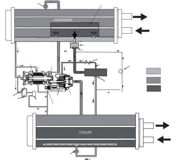
REFRIGERATION CYCLE
The compressor continuously draws refrigerant vapor from the cooler at a rate set by the amount of guide vane opening. As the compressor suction reduces the pressure in the cooler, the remaining refrigerant boils at a fairly low temperature (typically 38 to 42 F [3 to 6 C]). The energy required for boiling is obtained from the water flowing through the cooler tubes. With heat energy removed, the water becomes cold enough to use in an air-conditioning circuit or process liquid cooling.
After taking heat from the water, the refrigerant vapor is compressed. Compression adds still more heat energy and the refrigerant is quite warm (typically 98 to 102 F [37 to 40 C]) when it is discharged from the compressor into the condenser.
Relatively cool (typically 65 to 90 F [18 to 32 C]) water flowing into the condenser tubes removes heat from the refrigerant, and the vapor condenses to liquid. The liquid refrigerant passes through orifices into the FLASC (flash subcooler) chamber. Since the FLASC chamber is at a lower pressure, part of the liquid refrigerant flashes to vapor, thereby cooling the remaining liquid. The FLASC vapor is recondensed on the tubes which are cooled by entering condenser water. The liquid
drains into a high side float valve chamber between the FLASC chamber and the economizer. The refrigerant is then metered into the economizer. In the economizer, due to lower pressure, as liquid enters the chamber, some liquid will flash into a vapor and cool the remaining liquid. The separated vapor flows to the second stage of the compressor for greater cycle efficiency. A damper valve located on the economizer line to the compressor acts as a pressure regulating device to stabilize low load, low condensing pressure operating conditions. The damper will back up gas flow and thereby raises the economizer pressure to permit proper refrigerant flow through the economizer valve during those conditions.
The cooled liquid left in the economizer flows through a low side float valve and then into the cooler. The float valve forms a liquid seal to keep vapor from entering the cooler. Liquid refrigerant passes through the low side valve into the cooler. The refrigerant is now at a temperature and pressure at which the cycle began. Fig. 3 summarizes the refrigeration cycle.
ISOLATION
VALVE FLASC CHAMBER (OPTION)
CONDENSER
WATER
|
|
|
|
|
|
|
|
|
|
|
HIGH SIDE FLOAT CHAMBER |
|
|
|
|
|
|
|||
|
|
|
|
|
|
|
|
|
|
|
HIGH SIDE FLOAT VALVE |
HOT GAS BYPASS |
||||||||
|
|
|
|
|
|
|
|
|
|
|
|
|
|
|
|
|
||||
|
|
|
|
|
|
|
|
|
|
|
|
|
|
|
|
|
|
|
|
|
|
|
|
|
|
|
|
|
|
|
|
|
DAMPER |
|
|
|
|
|
|
||
|
|
|
|
|
|
|
|
|
|
|
|
|
|
|
|
|
|
|||
ROTOR |
ORIFICE |
|
|
|
|
|
|
|
|
|
|
VALVE |
|
|
|
|
|
HGBP |
||
TRANSMISSION |
|
REFRIGERANT |
|
|
|
|
|
|||||||||||||
|
FITTING |
|
ISOLATION VALVE |
|
|
VALVE |
||||||||||||||
|
|
|
|
|
|
|
|
|
|
|
|
|
|
|||||||
|
|
|
|
|
|
|
|
|
|
|
ECONOMIZER |
|
|
|
|
|
|
|||
|
|
|
|
|
|
|
|
|
|
|
|
LOW SIDE |
|
|
|
|
|
|
||
THERMOSTATIC |
|
|
IMPELLERS COMPRESSOR |
|
FLOAT VALVE |
|
|
|
||||||||||||
|
|
|
|
|
|
|
|
|
|
|
|
|||||||||
|
|
|
|
|
|
|
|
|
|
|
|
|||||||||
|
|
|
|
|
|
|
|
|
|
|
|
|||||||||
|
|
|
|
|
|
|
|
|
|
|
|
|||||||||
|
|
|
|
|
|
|
|
|
|
|
|
|||||||||
|
|
|
|
|
|
|
|
|
|
|
|
|||||||||
EXPANSION |
|
|
|
|
|
|
|
|
|
|
|
|
|
|
|
|
|
|
|
|
VALVE (TXV) |
OIL COOLER |
|||
|
|
|
|
|
|
|
|
|
BACK PRESSURE |
|
|
|
|
ORIFICE (INTEGRAL |
|
|
|
|
TO MOTOR SHELL) |
REFRIGERANT LIQUID
REFRIGERANT VAPOR
REFRIGERANT LIQUID/VAPOR
CHILLED
WATER
COOLER ISOLATION VALVE (OPTION)
Fig. 3 — Refrigeration Cycle — 19XR Two-Stage Compressor Frame Sizes 6 and 7
7
MOTOR AND OIL COOLING CYCLE
The motor and the lubricating oil are cooled by liquid refrigerant taken from the bottom of the condenser vessel (Fig. 3 and 4). Refrigerant flow is maintained by the pressure differential that exists due to compressor operation. After the refrigerant flows past an isolation valve, an in-line filter, and a sight glass/ moisture indicator, the flow is split between the motor cooling and oil cooling systems.
Flow to the motor cooling system passes through an orifice and into the motor. Once past the orifice, the refrigerant is directed over the motor by spray nozzles. The refrigerant collects in the bottom of the motor casing and is then drained back into the cooler through the motor refrigerant drain line. An orifice (in the motor shell) maintains a higher pressure in the motor shell than in the cooler. The motor is protected by a temperature sensor embedded in the stator windings. An increase in motor winding temperature past the motor override set point overrides the temperature capacity control to hold, and if the motor temperature rises 10 F (5.5 C) above this set point, the controls close the inlet guide vanes. If the temperature rises above the safety limit, the compressor shuts down.
Refrigerant that flows to the oil cooling system is regulated by expansion valves. The expansion valves regulate flow into the oil/refrigerant plate and frame-type heat exchanger (the oil cooler in Fig. 3), and control oil temperature to the bearings. The refrigerant leaving the oil cooler heat exchanger returns to the chiller cooler.
LUBRICATION CYCLE
Summary — The oil pump, oil filter, and oil cooler make up a package located partially in the transmission casing of the compressor-motor assembly. The oil is pumped into a filter assembly to remove foreign particles and is then forced into an oil cooler heat exchanger where the oil is cooled to proper operational temperatures. After the oil cooler, part of the flow is directed to the gears and the high speed shaft bearings; the remaining flow is directed to the motor shaft bearings. Oil drains into the transmission oil sump to complete the cycle (Fig. 3 and 4).
Details — Oil is charged into the lubrication system through a hand valve. Two sight glasses in the oil reservoir permit oil level observation. Normal oil level is between the middle of the upper sight glass and the top of the lower sight glass when the compressor is shut down. The oil level should be visible in at least one of the 2 sight glasses during operation. Oil sump temperature is displayed on the HMI default screen. During compressor operation, the oil sump temperature ranges between 125 and 150 F (52 and 66 C).
The oil pump suction is fed from the oil reservoir. An oil pressure relief valve maintains differential pressure in the system at the pump discharge. A range of 18 to 40 psid (124 to 172 kPad) is normal. This differential pressure can be read directly from the default HMI screen. The oil pump discharges oil to the oil filter assembly. This filter can be closed to permit removal of the filter without draining the entire oil system. The oil is then piped to the oil cooler heat exchanger. The oil cooler uses refrigerant from the condenser as the coolant. The refrigerant cools the oil to a temperature between 120 and 140 F (49 and 60 C).
As the oil leaves the oil cooler, it passes the oil pressure transducer and the sensor for the refrigerant expansion valve on the oil cooler. The oil is then divided. Part of the oil flows to the thrust bearing, forward pinion bearing, and gear spray. The rest of the oil lubricates the motor shaft bearings and the rear pinion bearing. The oil temperature is measured in the bearing housing as it leaves the bearings. The oil then drains into the oil reservoir at the base of the compressor. The control measures the temperature of the oil in the sump and maintains the temperature during shutdown. This temperature is read on the HMI default screen. See the Controls Operation and Troubleshooting Manual for details.
During the chiller start-up, the oil pump is energized and provides 40 seconds of lubrication to the bearings after pressure is verified before starting the compressor. During shutdown, the oil pump runs for 60 seconds to ensure lubrication as the compressor coasts to a stop.
The oil pump is a gerotor-style pump with external filters. A gerotor pump has two rotors, one is inside the other; their center points are offset with respect to each other. This type of pump provides a smooth continuous flow. It is also quieter than other designs. See Fig. 5.
Bearings — The 19XR compressor assemblies include a combination of radial bearings and thrust bearings. The low speed shaft assembly is supported by two journal bearings located on each end of the low speed shaft. The bearing closer to the bull gear includes a smaller babbitted thrust face, designed to handle axial forces.
Oil Reclaim System — The oil reclaim system returns oil lost from the compressor housing back to the oil reservoir by recovering the oil from 2 areas on the chiller. The guide vane housing is the primary area of recovery. Oil is also recovered by skimming it from the operating refrigerant level in the cooler vessel.
PRIMARY OIL RECOVERY MODE — Oil is normally recovered through the guide vane housing on the chiller. This is possible because oil is normally entrained with refrigerant in the chiller. As the compressor pulls the refrigerant up from the cooler into the guide vane housing to be compressed, the oil normally drops out at this point and falls to the bottom of the guide vane housing where it accumulates. Using discharge gas pressure to power an eductor, the oil is drawn from the housing and is discharged into the oil reservoir.
SECONDARY OIL RECOVERY METHOD — The secondary method of oil recovery is significant under light load conditions, when the refrigerant going up to the compressor suction does not have enough velocity to bring oil along. Under these conditions, oil collects in a greater concentration at the top level of the refrigerant in the cooler. Using discharge gas to power eductors, this oil and refrigerant mixture is skimmed from the side of the cooler and is then drawn up to the guide vane housing. There is a filter in this line. Because the guide vane housing pressure is much lower than the cooler pressure, the refrigerant boils off, leaving the oil behind to be collected by the primary oil recovery method.
8

10 |
|
1 |
2
3
9
|
|
|
4 |
|
|
|
5 |
|
|
|
6 |
|
|
|
7 |
|
OIL LINE |
8 |
|
|
|
|
|
|
VENT LINE |
|
a19- |
|
|
LEGEND |
|
1 |
— Motor Stator |
6 |
— Oil Heater |
2 |
— Impellers |
7 |
— Oil Pump |
3 |
— Variable Inlet Guide Vanes |
8 |
— Oil Filters |
4 |
— Transmission |
9 |
— Motor Rotor |
5 |
— High Speed Shaft Bearings |
10 |
— Motor Shaft Bearings |
Fig. 4 — 19XR Two-Stage Compressor Lubrication System
a19-2116
3
1
|
|
|
2 |
LEGEND |
|
|
|
1 |
— Gerotor Oil Pump |
|
|
|
2 |
— Oil Pressure Regulator Valve |
|
|
|
3 |
— Oil Sump Pressure Transducer |
|
|
|
4 |
— Oil Sump Drain Valve |
|
|
|
5 |
— High Speed Compressor End Bearing, |
|
|
|
|
Temperature Terminal Block |
|
|
|
6 |
— Low Speed Compressor End Bearing, |
|
|
|
|
Temperature Cable |
|
|
5 |
7 |
— Compressor Oil Sump Temperature |
8 |
7 |
6 |
8 |
— Oil Heater |
|
|
4 |
|
Fig. 5 — Gerotor Oil Pump
9
STARTING EQUIPMENT
The 19XR chiller requires a motor starter to operate the centrifugal hermetic compressor motor, the oil pump, and various auxiliary equipment components. The starter is the main field wiring interface for the contractor.
See Carrier’s specification for specific starter requirements. All starters must meet these specifications in order to properly start and satisfy mechanical safety requirements.
It is possible that there are two separate circuit breakers inside the starter. These include (1) the main compressor motor circuit breaker, and (2) a circuit breaker which provides power to the chiller control panel. The latter is typically wired in parallel with the first so that power is provided to those services when the main breaker is open. The disconnect switch on the starter front cover is connected to the main breaker. Typically, separate 3-phase power sources as per job requirements are supplied to the control panel to power the oil pump, heater, and controls.
WARNING 
The main circuit breaker on the front of the starter disconnects the main motor power only. Power may be still energized for other circuits. Always check wiring diagrams before initiating any work on the chiller and follow applicable lock-out/tag-out procedures. Failure to disconnect power will result in personal injury.
All starters must include a Carrier control module called the Integrated Starter Module (ISM). This module controls and monitors all aspects of the starter. See the Controls Operation and Troubleshooting guide for additional ISM information. Contact Carrier’s Replacement Component Division (RCD) for replacement parts.
Solid-State Starter (Optional) — The 19XR chiller may be equipped with a solid-state, reduced-voltage starter. This starter’s primary function is to provide on-off control of the compressor motor. This type of starter reduces the peak starting torque, controls the motor inrush current, and decreases mechanical shock. This capability is summed up by the phrase “soft starting.” Consult E-Cat for full information about starter offerings. The solid-state starter manufacturer’s name is located inside the starter access door.
A solid-state, reduced-voltage starter operates by reducing the starting voltage. The starting torque of a motor at full voltage is typically 125% to 175% of the running torque. When the voltage and the current are reduced at start-up, the starting torque is reduced as well. The object is to reduce the starting voltage to adjust the voltage necessary to develop the torque required to get the motor moving. The voltage is reduced by silicon controlled rectifiers (SCRs). The voltage and current are then ramped up in a desired period of time. Once full voltage is reached, a bypass contactor is energized to bypass the SCRs.
WARNING 
When voltage is supplied to the solid-state circuitry (CB1 is closed), the heat sinks in the starter as well as the wires leading to the motor and the motor terminal are at line voltage. Do not touch the heat sinks, power wiring, or motor terminals while voltage is present or serious injury will result.
The display on the front of the solid-state starter is useful for troubleshooting and starter checkout. The display indicates:
•line voltage
•control voltage status
•power indication
•proper phasing for rotation
•start circuit energized
•ground fault
•current unbalance
•run state
The starter is further explained in the Check Starter section, page 19.
Freestanding Medium Voltage VFD
(Optional) — For optimum efficiency, the 19XR chiller can be combined with a VFD (variable frequency drive). This option is a freestanding, medium voltage current source drive that does not require a transformer between the power source and the drive. The drive meets IEEE-519 specifications.
CONTROLS
Definitions
ANALOG SIGNAL — An analog signal varies in proportion to the monitored source. It quantifies values between operating limits. (Example: A temperature sensor is an analog device because its resistance changes in proportion to the temperature, generating many values.)
DISCRETE SIGNAL — A discrete signal is a 2-position representation of the value of a monitored source. (Example: A switch produces a discrete signal indicating whether a value is above or below a set point or boundary by generating an on/off, high/low, or open/closed signal.)
General — The 19XR centrifugal liquid chiller contains a microprocessor-based control center that monitors and controls all operations of the chiller. The microprocessor control system matches the cooling capacity of the chiller to the cooling load while providing state-of-the-art chiller protection. The system controls cooling load within the set point plus the deadband by sensing the leaving chilled water or brine temperature and regulating the inlet guide vane via a mechanically linked actuator motor. The guide vane is a variable flow pre-whirl assembly that controls the refrigeration effect in the cooler by regulating the amount of refrigerant vapor flow into the compressor. An increase in guide vane opening increases capacity. A decrease in guide vane opening decreases capacity. The microprocessorbased control center protects the chiller by monitoring the digital and analog inputs and executing capacity overrides or safety shutdowns, if required.
PIC 5 System Components — The chiller control system is called the PIC 5 (Product Integrated Control 5). See Table 1. As with previous PIC versions, the PIC 5 system controls the operation of the chiller by monitoring all operating conditions. The PIC 5 control system can diagnose a problem and let the operator know what the problem is and what to check. It promptly positions the guide vanes to maintain leaving chilled water temperature. It can interface with auxiliary equipment such as pumps and cooling tower fans to turn them on when required. It continually checks all safeties to prevent any unsafe operating condition. It also regulates the oil heater while the compressor is off and regulates the hot gas bypass valve, if installed. The PIC 5 controls provide critical protection for the compressor motor and control the motor starter.
10
Table 1 — Major PIC 5 Components and
Panel Locations
PIC 5 COMPONENT |
PANEL LOCATION |
Chiller Human Machine Interface (HMI) |
HMI Control Panel |
and Display |
|
Integrated Starter Module (ISM) |
Starter Cabinet |
Chiller IO Boards |
Control Panel |
Oil Heater Contactor (1C) |
Control Panel |
Oil Pump Contactor (2C) |
Control Panel |
Hot Gas Bypass Relays (HCLR, HOPR) |
Control Panel |
(Optional) |
|
Control Transformers (T1, T2, T3) |
Control Panel |
Temperature Sensors |
See Fig. 2 and Fig. 5 |
Pressure Transducers |
See Fig. 2 and Fig. 5 |
NOTE: For detailed information about the PIC 5 HMI (human machine interface), see the 19XR with PIC 5 Controls Operation and Troubleshooting manual.
START-UP/SHUTDOWN/
RECYCLE SEQUENCE
Local Start/Stop Control — Local start-up (or manual start-up) is initiated by pressing the the gray Start/Stop icon on the HMI interface. See Fig. 6.
Fig. 6 — Chiller Start/Stop Icon
This initiates the PIC 5 starting sequence by displaying the list of operating modes. Press Local On to initiate start-up. See Fig. 7.
Unit Start/Stop
When start-up is initiated the status screen displays the startup progress and the Start/Stop icon blinks green.
Once local start-up begins, the PIC 5 control system performs a series of pre-start tests to verify that all pre-start alerts and safeties are within acceptable limits. Table 2 shows appropriate Prestart Alerts/Alarms conditions. If a test is not successful, the start-up is delayed or aborted. If the tests are successful, the start-up will be in progress and the COMPRESSOR RUN STATUS shall be “Startup.” The control shall then energize the chilled water/brine pump relay.
Five seconds later, the condenser pump relay energizes. Thirty seconds later the PIC 5 control system monitors the chilled water and condenser water flow devices and waits until the WATER FLOW VERIFY TIME (operator-configured, default 5 minutes) expires to confirm flow. After flow is verified, the chilled water temperature is compared to CONTROL POINT plus 1/2 CHILLED WATER DEADBAND. If the temperature is less than or equal to this value, the PIC 5 control system turns off the condenser pump relay and goes into a Recycle mode.
If the water/brine temperature is high enough, the start-up sequence continues and checks the guide vane position. If the guide vanes are more than 4% open, the start-up waits until the PIC 5 control system closes the vanes. If the vanes are closed and the oil pump pressure is less than 4 psi (27.6 kPa), the oil pump relay energizes. The PIC 5 control system then waits until the oil pressure (OIL PRESS VERIFY TIME, operator-con- figured, default of 40 seconds) reaches a maximum of 18 psi (124 kPa). After oil pressure is verified, the PIC control system waits 40 seconds, and the compressor start relay (1CR) energizes to start the compressor.
Compressor ontime and service ontime timers start, and the compressor STARTS IN 12 HOURS counter and the number of starts over a 12-hour period counter advance by one.
Failure to verify any of the requirements up to this point will result in the PIC 5 control system aborting the start and displaying the applicable pre-start alert alarm state number near the bottom of the home screen on the HMI panel. A prestart failure does not advance the STARTS IN 12 HOURS counter. Any failure after the 1CR relay has energized results in a safety shutdown, advances the starts in 12 hours counter by one, and displays the applicable shutdown status on the display.
The minimum time to complete the entire prestart sequence is approximately 185 seconds. See Fig. 8 for normal start-up timing sequence. See Table 2 for a list of prestart checks.
Fig. 7 — Local On a19-2118
NOTE: Prior to start-up the start-to-start timer and the stop-to- start timer must have elapsed and all alarms must be cleared (see Troubleshooting Guide section on page 42).
11
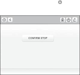
Table 2 — Prestart Checks
PRESTART CHECK CONDITION* |
STATE NUMBER† |
STARTS IN 12 HOURS 8 (not counting recycle restarts or auto restarts after power failure) |
Alert – 100 |
OIL SUMP TEMP 140° F (60° C) and OIL SUMP TEMP EVAP_SAT + 50° F (27.8° C) |
Alert – 101 |
COND PRESSURE COND PRESS OVERRIDE – 20 psi |
Alert – 102 |
#RECYCLE RESTARTS LAST 4 HOURS > 5 |
Alert – 103 |
COMP BEARING TEMPS COMP BEARING ALERT – 10° F (5.6° C) |
Alarm – 230 |
COMP MOTOR WINDING TEMP COMP MOTOR WINDING – 10° F (5.6° C) |
Alarm – 231 |
COMP DISCHARGE TEMPERATURE COMP DISCHARGE ALERT – 10° F (5.6° C) |
Alarm – 232 |
EVAP_SAT <Evap trip point** + EVAP OVERRIDE DELTA T |
Alarm – 233 |
EVAP REFRIG LIQUID TEMP <Evap trip point** + EVAP OVERRIDE DELTA T |
Alarm – 233 |
AVERAGE LINE VOLTAGE UNDERVOLTAGE THRESHOLD |
Alarm – 234 |
AVERAGE LINE VOLTAGE OVERVOLTAGE THRESHOLD |
Alarm – 235 |
CHECK FOR GUIDE VANE CALIBRATION |
Alarm – 236 |
* If Prestart Check Condition is True, then resulting State is as indicated in the State Number column.
†See the Controls Operation and Troubleshooting guide for alarm and alert codes. **Evap trip point = 33 F (0.6 C) (water) or EVAP REFRIG TRIPPOINT (brine)
A B |
C D E |
F G |
O/A |
A— START INITIATED: Pre-start checks are made; evaporator pump started.*
B— Condenser water pump started (5 seconds after A).
C— Water flows verified (30 seconds to 5 minutes maximum after B). Chilled water temperatures checked against control point. Guide vanes checked for closure. Oil pump started; tower fan control enabled.
D— Oil pressure verified (15 seconds minimum, 300 seconds maximum after C).
E— Compressor motor starts; compressor ontime and service ontime start, 15-minute inhibit timer starts (10 seconds after D), total compressor starts advances by one, and the number of starts over a 12-hour period advances by one.
F— SHUTDOWN INITIATED — Compressor motor stops; compressor ontime and service ontime stop, and 1-minute inhibit timer starts.
G— Oil pump and evaporator pumps deenergized (60 seconds after F). Condenser pump and tower fan control may continue to operate if condenser pressure is high. Evaporator pump may continue if in RECYCLE mode.
O/A —
* Auto Restart After Power Failure Timing sequence will be faster.
Fig. 8 — Control Timing Sequence
for Normal Start-Up
Lubrication Control — As part of the prestart checks executed by the controls, the oil sump temperature is compared to the evaporator saturated refrigerant temperature. If the oil temperature is less than 140 F (60 C) and less than evaporator saturated refrigerant temperature plus 50° F (27.8° C), the start-up will be delayed until either of these conditions is no longer true. Once this temperature is confirmed, the start-up continues.
The oil heater relay is energized whenever the chiller compressor is off and the oil sump temperature is less than 140 F (60 C) or the oil sump temperature is less than the evaporator saturated refrigerant temperature plus 53° F (29.4° C). The oil heater is turned off when either of the following conditions is true:
•Oil sump temperature is more than 152 F (66.7 C)
•Oil sump temperature is more than 144 F (62.2 C) and more than the evaporator saturated refrigerant temperature plus 55° F (30.6° C)
The oil heater is always off when the compressor is running.
The oil pump is also energized for 30 seconds after each 30 minutes of oil heat relay being energized in order to stir the oil for more evenly distributed heating.
Shutdown — The unit can be stopped locally using the HMI by pressing the green Start/Stop icon . The Unit Start/ Stop screen is displayed. Press Confirm Stop (see Fig. 9).
Unit Start/Stop
Fig. 9 — Confirm Stop |
a19-2122 |
12
BEFORE INITIAL START-UP
Job Data Required
•list of applicable design temperatures and pressures (product data submittal)
•chiller certified prints
•starting equipment details and wiring diagrams
•diagrams and instructions for special controls or options
•19XR Installation Instructions
Equipment Required
•mechanic’s tools (refrigeration)
•digital volt-ohmmeter (DVM)
•true RMS (root mean square) digital multimeter with clamp-on current probe or true RMS digital clamp-on ammeter for at least 480 vac
•electronic leak detector
•absolute pressure manometer or wet-bulb vacuum indicator (see Fig. 10)
•insulation tester for compressor motor rated at motor design voltage
Fig. 10 — Typical Wet-Bulb Type
Vacuum Indicator
Remove Shipping Packaging — Remove any packaging material from the unit and starter.
Open Oil Circuit Valves — Check to ensure the oil filter isolation valves are open by removing the valve cap and checking the valve stem.
Tighten All Gasketed Joints — Gaskets normally relax by the time the chiller arrives at the jobsite. Tighten all gasketed joints to ensure a leak-tight chiller (does not apply to refrigerant joints covered by factory insulation). Gasketed joints (excluding O-rings) may include joints at some or all of the following:
•waterbox covers
•compressor suction elbow flanges (at compressor and at the cooler)
•compressor discharge flange
•compressor discharge line spacer (both sides) if no isolation valve
•cooler inlet line spacer (both sides) if no isolation valve
•hot gas bypass valve (both sides of valve)
•hot gas bypass flange at compressor
See Tables 3 and 4 for bolt torque requirements.
Check Chiller Tightness — Figure 11 outlines the proper sequence and procedures for leak testing.
The 19XR chillers are shipped with the refrigerant contained in the condenser shell and the oil charge in the compressor. The cooler is shipped with a 15 psig (103 kPa) refrigerant charge. Units may be ordered with the refrigerant shipped separately, along with a 15 psig (103 kPa) nitrogen-holding charge in each vessel.
To determine if there are any leaks, the chiller should be charged with refrigerant. Use an electronic leak detector to check all flanges and solder joints after the chiller is pressurized. If any leaks are detected, follow the leak test procedure (page 16).
If the chiller is spring isolated, keep all springs blocked in both directions to prevent possible piping stress and damage during the transfer of refrigerant from vessel to vessel during the leak test process, or any time refrigerant is being transferred. Adjust the springs when the refrigerant is in operating condition and the water circuits are full.
13
Table 3 — Bolt Torque Requirements, Foot Pounds
|
SAE 2, A307 GR A |
|
SAE 5 |
|
SAE 8 |
||||
|
|
HEX HEAD |
|||||||
|
HEX HEAD |
SOCKET HEAD OR HEX |
|||||||
BOLT SIZE |
WITH 6 RADIAL LINES OR |
||||||||
NO MARKS |
WITH 3 RADIAL LINES, OR SA499 |
||||||||
(in.) |
SA354 GR BD |
||||||||
LOW CARBON STEEL |
MEDIUM CARBON STEEL |
||||||||
|
MEDIUM CARBON STEEL |
||||||||
|
|
|
|
|
|
||||
|
MINIMUM |
MAXIMUM |
MINIMUM |
|
MAXIMUM |
MINIMUM |
|
MAXIMUM |
|
1/4 |
4 |
6 |
6 |
|
9 |
9 |
|
13 |
|
5/16 |
8 |
11 |
13 |
|
18 |
20 |
|
28 |
|
3/8 |
13 |
19 |
22 |
|
31 |
32 |
|
46 |
|
7/16 |
21 |
30 |
35 |
|
50 |
53 |
|
75 |
|
1/2 |
32 |
45 |
53 |
|
75 |
80 |
|
115 |
|
9/16 |
46 |
65 |
75 |
|
110 |
115 |
|
165 |
|
5/8 |
65 |
95 |
105 |
|
150 |
160 |
|
225 |
|
3/4 |
105 |
150 |
175 |
|
250 |
260 |
|
370 |
|
7/8 |
140 |
200 |
265 |
|
380 |
415 |
|
590 |
|
1 |
210 |
300 |
410 |
|
580 |
625 |
|
893 |
|
11/8 |
330 |
475 |
545 |
|
780 |
985 |
|
1,410 |
|
11/4 |
460 |
660 |
770 |
|
1,100 |
1,380 |
|
1,960 |
|
13/8 |
620 |
885 |
1,020 |
|
1,460 |
1,840 |
|
2,630 |
|
11/2 |
740 |
1060 |
1,220 |
|
1,750 |
2,200 |
|
3,150 |
|
15/8 |
1010 |
1450 |
1,670 |
|
2,390 |
3,020 |
|
4,310 |
|
13/4 |
1320 |
1890 |
2,180 |
|
3,110 |
3,930 |
|
5,610 |
|
17/8 |
1630 |
2340 |
2,930 |
|
4,190 |
5,280 |
|
7,550 |
|
2 |
1900 |
2720 |
3,150 |
|
4,500 |
5,670 |
|
8,100 |
|
21/4 |
2180 |
3120 |
4,550 |
|
6,500 |
8,200 |
|
11,710 |
|
21/2 |
3070 |
4380 |
5,000 |
|
7,140 |
11,350 |
|
16,210 |
|
23/4 |
5120 |
7320 |
8,460 |
|
12,090 |
15,710 |
|
22,440 |
|
3 |
6620 |
9460 |
11,040 |
|
15,770 |
19,900 |
|
28,440 |
|
Table 4 — Bolt Torque Requirements, Foot Pounds (Metric Bolts)
BOLT SIZE |
|
CLASS 8.8 |
|
CLASS 10.9 |
||
(METRIC) |
MINIMUM |
|
MAXIMUM |
MINIMUM |
|
MAXIMUM |
M4 |
1.75 |
|
2.5 |
2.5 |
|
3.5 |
M6 |
6 |
|
9 |
8 |
|
12 |
M8 |
14 |
|
20 |
20 |
|
30 |
|
|
|
|
|
|
|
M10 |
28 |
|
40 |
40 |
|
57 |
M12 |
48 |
|
70 |
70 |
|
100 |
M16 |
118 |
|
170 |
170 |
|
240 |
|
|
|
|
|
|
|
M20 |
230 |
|
330 |
330 |
|
470 |
M24 |
400 |
|
570 |
570 |
|
810 |
M27 |
580 |
|
830 |
820 |
|
1175 |
14
5 AND 6)
5 AND 6)
Fig. 11 — 19XR Leak Test Procedures
a19-1151tf.eps
15
Refrigerant Tracer — Carrier recommends the use of an environmentally acceptable refrigerant tracer for leak testing with an electronic detector.
Ultrasonic leak detectors can also be used if the chiller is under pressure.
WARNING 
Do not use air or oxygen as a means of pressurizing the chiller. Mixtures of HFC-134a and air can undergo combustion, resulting in equipment damage and possible personal injury.
Leak Test Chiller — Due to regulations regarding refrigerant emissions and the difficulties associated with separating contaminants from the refrigerant, Carrier recommends the following leak test procedure. Refer to Tables 5 and 6 for refrigerant pressure/temperature values.
1.If the pressure readings are normal for the chiller condition:
a.Evacuate the holding charge from the vessels, if present.
b.Raise the chiller pressure, if necessary, by adding refrigerant until pressure is at the equivalent saturated pressure for the surrounding temperature. Follow pumpout procedures in the Transfer Refrigerant from Pumpout Storage Tank to Chiller section, Steps 1a-e, page 34.
CAUTION
Never charge liquid refrigerant into the chiller if the pressure in the chiller is less than 35 psig (241 kPa) for HFC134a. Charge as a gas only, with the cooler and condenser pumps running, until this pressure is reached, using PUMPDOWN/LOCKOUT (located in the Maintenance menu) and TERMINATE LOCKOUT mode on the PIC 5 control interface. Flashing of liquid refrigerant at low pressures can cause tube freeze-up and considerable damage.
c.Leak test chiller as outlined in Steps 3 to 9.
2.If the pressure readings are abnormal for the chiller condition:
a.Prepare to leak test chillers shipped with refrigerant (Step 2h).
b.Check for large leaks by connecting a nitrogen bottle and raising the pressure to 30 psig (207 kPa). Soap test all joints. If the test pressure holds for 30 minutes, prepare the test for small leaks (Steps 2g and 2h).
c.Plainly mark any leaks that are found.
d.Release the pressure in the system.
e.Repair all leaks.
f.Retest the joints that were repaired.
g.After successfully completing the test for large leaks, remove as much nitrogen, air, and moisture as possible, given the fact that small leaks may be present in the system. This can be accomplished by following the dehydration procedure outlined in the Chiller Dehydration section, page 18.
h.Slowly raise the system pressure to a maximum of 160 psig (1103 kPa) but no less than 35 psig (241 kPa) for HFC-134a by adding refrigerant. Proceed with the test for small leaks (Steps 3 to 9).
3.Check the chiller carefully with an electronic leak detector or soap bubble solution.
4.Leak Determination — If an electronic leak detector indicates a leak, use a soap bubble solution, if possible, to confirm. Total all leak rates for the entire chiller. Leakage at rates greater than 0.1% of the total charge per year must be repaired. Note the total chiller leak rate on the start-up report.
5.If no leak is found during the initial start-up procedures, complete the transfer of refrigerant gas from the storage tank to the chiller. Retest for leaks.
6.If no leak is found after a retest:
a.Transfer the refrigerant to the storage tank and perform a standing vacuum test as outlined in the Standing Vacuum Test section, below.
b.If the chiller fails the standing vacuum test, check for large leaks (Step 2b).
c.If the chiller passes the standing vacuum test,
dehydrate the chiller. Follow the procedure in the Chiller Dehydration section, page 18. Charge the chiller with refrigerant.
7.If a leak is found after a retest, pump the refrigerant back into the storage tank or, if isolation valves are present, pump the refrigerant into the non-leaking vessel. See the Transfer Refrigerant from Pumpout Storage Tank to Chiller section on page 34.
8.Transfer the refrigerant until the chiller pressure is at 18 in. Hg (40 kPa absolute).
9.Repair the leak and repeat the procedure, beginning from Step 2h, to ensure a leak-tight repair. (If the chiller is opened to the atmosphere for an extended period, evacuate it before repeating the leak test.)
Standing Vacuum Test — When performing the standing vacuum test or chiller dehydration, use a manometer or a wet bulb indicator. Dial gages cannot indicate the small amount of acceptable leakage during a short period of time.
1.Attach an absolute pressure manometer or wet bulb indicator to the chiller.
2.Evacuate the vessel to at least 18 in. Hg vac (41 kPa [abs]), using a vacuum pump or the pumpout unit.
3.Valve off the pump to hold the vacuum and record the manometer or indicator reading.
4.a. If the leakage rate is less than 0.05 in. Hg (0.17 kPa) in 24 hours, the chiller is sufficiently tight.
b.If the leakage rate exceeds 0.05 in. Hg (0.17 kPa) in 24 hours, re-pressurize the vessel and test for leaks if refrigerant is available. If not, use nitrogen and a refrigerant tracer. Raise the vessel pressure in increments until the leak is detected. If refrigerant is used, the maximum gas pressure is approximately 70 psig (483 kPa) for HFC-134a at normal ambient temperature. If nitrogen is used, limit the leak test pressure to 160 psig (1103 kPa) maximum.
5.Repair the leak, retest, and proceed with dehydration.
16
Table 5 — HFC-134a Pressure —
Temperature (F)
TEMPERATURE |
PRESSURE |
(F) |
(PSIG) |
0 |
6.50 |
2 |
7.52 |
4 |
8.60 |
6 |
9.66 |
8 |
10.79 |
10 |
11.96 |
12 |
13.17 |
14 |
14.42 |
16 |
15.72 |
18 |
17.06 |
20 |
18.45 |
22 |
19.88 |
24 |
21.37 |
26 |
22.90 |
28 |
24.48 |
30 |
26.11 |
32 |
27.80 |
34 |
29.53 |
36 |
31.32 |
38 |
33.17 |
40 |
35.08 |
42 |
37.04 |
44 |
39.06 |
46 |
41.14 |
48 |
43.28 |
50 |
45.48 |
52 |
47.74 |
54 |
50.07 |
56 |
52.47 |
58 |
54.93 |
60 |
57.46 |
62 |
60.06 |
64 |
62.73 |
66 |
65.47 |
68 |
68.29 |
70 |
71.18 |
72 |
74.14 |
74 |
77.18 |
76 |
80.30 |
78 |
83.49 |
80 |
86.17 |
82 |
90.13 |
84 |
93.57 |
86 |
97.09 |
88 |
100.70 |
90 |
104.40 |
92 |
108.18 |
94 |
112.06 |
96 |
116.02 |
98 |
120.08 |
100 |
124.23 |
102 |
128.47 |
104 |
132.81 |
106 |
137.25 |
108 |
141.79 |
110 |
146.43 |
112 |
151.17 |
114 |
156.01 |
116 |
160.96 |
118 |
166.01 |
120 |
171.17 |
122 |
176.45 |
124 |
181.83 |
126 |
187.32 |
128 |
192.93 |
130 |
198.66 |
132 |
204.50 |
134 |
210.47 |
136 |
216.55 |
138 |
222.76 |
140 |
229.09 |
Table 6 — HFC-134a Pressure —
Temperature (C)
TEMPERATURE |
PRESSURE |
(C) |
(KPA) |
–18.0 |
44.8 |
–16.7 |
51.9 |
–15.6 |
59.3 |
–14.4 |
66.6 |
–13.3 |
74.4 |
–12.2 |
82.5 |
–11.1 |
90.8 |
–10.0 |
99.4 |
–8.9 |
108.0 |
–7.8 |
118.0 |
–6.7 |
127.0 |
–5.6 |
137.0 |
–4.4 |
147.0 |
–3.3 |
158.0 |
–2.2 |
169.0 |
–1.1 |
180.0 |
0.0 |
192.0 |
1.1 |
204.0 |
2.2 |
216.0 |
3.3 |
229.0 |
4.4 |
242.0 |
5.0 |
248.0 |
5.6 |
255.0 |
6.1 |
261.0 |
6.7 |
269.0 |
7.2 |
276.0 |
7.8 |
284.0 |
8.3 |
290.0 |
8.9 |
298.0 |
9.4 |
305.0 |
10.0 |
314.0 |
11.1 |
329.0 |
12.2 |
345.0 |
13.3 |
362.0 |
14.4 |
379.0 |
15.6 |
396.0 |
16.7 |
414.0 |
17.8 |
433.0 |
18.9 |
451.0 |
20.0 |
471.0 |
21.1 |
491.0 |
22.2 |
511.0 |
23.3 |
532.0 |
24.4 |
554.0 |
25.6 |
576.0 |
26.7 |
598.0 |
27.8 |
621.0 |
28.9 |
645.0 |
30.0 |
669.0 |
31.1 |
694.0 |
32.2 |
720.0 |
33.3 |
746.0 |
34.4 |
773.0 |
35.6 |
800.0 |
36.7 |
828.0 |
37.8 |
857.0 |
38.9 |
886.0 |
40.0 |
916.0 |
41.1 |
946.0 |
42.2 |
978.0 |
43.3 |
1010.0 |
44.4 |
1042.0 |
45.6 |
1076.0 |
46.7 |
1110.0 |
47.8 |
1145.0 |
48.9 |
1180.0 |
50.0 |
1217.0 |
51.1 |
1254.0 |
52.2 |
1292.0 |
53.3 |
1330.0 |
54.4 |
1370.0 |
55.6 |
1410.0 |
56.7 |
1451.0 |
57.8 |
1493.0 |
58.9 |
1536.0 |
60.0 |
1580.0 |
17
Chiller Dehydration — Dehydration is recommended if the chiller has been open for a considerable period of time, if the chiller is known to contain moisture, or if there has been a complete loss of chiller holding charge or refrigerant pressure.
CAUTION
Do not start or megohm-test the compressor motor or oil pump motor, even for a rotation check, if the chiller is under dehydration vacuum. Insulation breakdown and severe damage may result.
WARNING 
Starters must be disconnected by an isolation switch before placing the machine under a vacuum. To be safe, isolate any starter before evacuating the chiller if you are not sure if there are live leads to the hermetic motor.
Dehydration can be done at room temperatures. Using a cold trap (Fig. 12) may substantially reduce the time required to complete the dehydration. The higher the room temperature, the faster dehydration takes place. At low room temperatures, a very deep vacuum is required to boil off any moisture. If low ambient temperatures are involved, contact a qualified service representative for the dehydration techniques required.
Perform dehydration as follows:
1.Connect a high capacity vacuum pump (5 cfm [.002 m3/s] or larger is recommended) to the refrigerant charging valve (Fig. 2). Tubing from the pump to the chiller should be as short in length and as large in diameter as possible to provide least resistance to gas flow.
2.Use an absolute pressure manometer or a wet bulb vacuum indicator to measure the vacuum. Open the shutoff valve to the vacuum indicator only when taking a reading. Leave the valve open for 3 minutes to allow the indicator vacuum to equalize with the chiller vacuum.
3.If the entire chiller is to be dehydrated, open all isolation valves (if present).
4.With the chiller ambient temperature at 60 F (15.6 C) or higher, operate the vacuum pump until the manometer reads 185 psig (1275 kPa), or a vacuum indicator reads 35 F (1.7 C). Operate the pump an additional 2 hours.
Do not apply a greater vacuum than 29.82 in. Hg vac (757.4 mm Hg) or go below 33 F (0.56 C) on the wet bulb vacuum indicator. At this temperature and pressure, isolated pockets of moisture can turn into ice. The slow rate of evaporation (sublimation) of ice at these low temperatures and pressures greatly increases dehydration time.
5.Valve off the vacuum pump, stop the pump, and record the instrument reading.
6.After a 2-hour wait, take another instrument reading. If the reading has not changed, dehydration is complete. If the reading indicates vacuum loss, repeat Steps 4 and 5.
7.If the reading continues to change after several attempts, perform a leak test up to the maximum 160 psig (1103 kPa) pressure. Locate and repair the leak, and repeat dehydration.
8.Once dehydration is complete, the evacuation process can continue. The final vacuum prior to charging the unit with refrigerant should in all cases be 29.9 in Hg (500 microns, 0.07 kPa [abs]) or less.
Fig. 12 — Dehydration Cold Trap
Inspect Water Piping — Refer to piping diagrams provided in the certified drawings and the piping instructions in the 19XR Installation Instructions manual. Inspect the piping to the cooler and condenser. Be sure that the flow directions are correct and that all piping specifications have been met.
Piping systems must be properly vented with no stress on waterbox nozzles and covers. Water flows through the cooler and condenser must meet job requirements. Measure the pressure drop across the cooler and the condenser.
 CAUTION
Water must be within design limits, clean, and treated to ensure proper chiller performance and to reduce the potential of tube damage due to corrosion, scaling, or erosion. Carrier assumes no responsibility for chiller damage resulting from untreated or improperly treated water.
Check Relief Valves — Be sure the relief valves have been piped to the outdoors in compliance with the latest edition of ANSI/ASHRAE Standard 15 and applicable local safety codes. Piping connections must allow for access to the valve mechanism for periodic inspection and leak testing.
The standard 19XR relief valves are set to relieve at 185 psig (1275 kPa) chiller design pressure.
Inspect Wiring
 WARNING
Do not check the voltage supply without proper equipment and precautions. Serious injury may result. Follow power company recommendations.
 CAUTION
Do not apply any kind of test voltage, even for a rotation check, if the chiller is under a dehydration vacuum. Insulation breakdown and serious damage may result.
1.Examine the wiring for conformance to the job wiring diagrams and all applicable electrical codes.
2.Compare the ampere rating on the starter nameplate to rating on the compressor nameplate. The overload trip amps must be 108% to 120% of the rated load amps.
3.The starter for a centrifugal compressor motor must contain the components and terminals required for PIC 5 controls platform. Check the certified drawings.
4.Check the voltage to the components and compare it to the nameplate values.
5.Ensure that fused disconnects or circuit breakers have been supplied for the control panel.
18
6.Ensure all electrical equipment and controls are properly grounded in accordance with job drawings, certified drawings, and all applicable electrical codes.
7.Ensure the customer’s contractor has verified proper operation of the pumps, cooling tower fans, and associated auxiliary equipment. This includes ensuring motors are properly lubricated and have proper electrical supply and proper rotation.
8.Test the chiller compressor motor and its power lead insulation resistance with an insulation tester such as a megohmmeter. (Use a tester rated for motor voltage.)
a.Open the starter main disconnect switch and follow lockout/tagout rules.
CAUTION
If the motor starter is a solid-state starter, the motor leads must be disconnected from the starter before an insulation test is performed. The voltage generated from the tester can damage the starter solid-state components.
b.With the tester connected to the motor leads, take 10-second and 60-second megohm readings as follows:
3-Lead Motor — Tie terminals 1, 2, and 3 together and test between the group and ground.
c.Divide the 60-second resistance reading by the 10-second reading. The ratio, or polarization index, must be one or higher. Both the 10 and 60-second readings must be at least 50 megohms.
If the readings on a field-installed starter are unsatisfactory, repeat the test at the motor with the power leads disconnected. Satisfactory readings in this second test indicate the fault is in the power leads.
Check Starter
WARNING 
BE AWARE that certain automatic start arrangements can engage the starter. Open the disconnect ahead of the starter in addition to shutting off the chiller or pump. Failure to follow this procedure may result in personal injury by electric shock.
Use the instruction and service manual supplied by the starter manufacturer to verify the starter has been installed correctly, to set up and calibrate the starter, and for complete troubleshooting information.
WARNING 
The main disconnect on the starter front panel may not deenergize all internal circuits. Open all internal and remote disconnects before servicing the starter. Failure to follow this procedure may result in personal injury by electric shock.
MECHANICAL STARTER
1.Check all field wiring connections for tightness, clearance from moving parts, and correct connection.
2.Check the contactor(s) to ensure they move freely. Check all other electro-mechanical devices, such as relays, for free movement. If the devices do not move freely, contact the starter manufacturer for replacement components.
3.Reapply starter control power (not main chiller power) to check the electrical functions.
Ensure the starter (with relay 1CR closed) goes through a complete and proper start cycle.
SOLID-STATE STARTER
 WARNING
This equipment is at line voltage when AC power is connected. Pressing the STOP button does not remove voltage.
 CAUTION
An isolation switch or circuit breaker must be open ahead of any solid-state starter when the chiller is in a vacuum. If not, damage to the machine may result.
1.Ensure all wiring connections are properly terminated to the starter.
2.Verify the ground wire to the starter is installed properly and is sufficient size.
3.Verify the motors are properly grounded to the starter.
4.Verify the proper ac input voltage is brought into the starter according to the certified drawings.
5.Apply power to the starter.
Oil Charge — The oil charge for the 19XR two-stage compressor frame size 6 is 29 gal (110 L); for frame size 7 the oil charge is 44.5 gal (168 L).
The chiller is shipped with oil in the compressor. When the sump is full, the oil level should be no higher than the middle of the upper sight glass, and minimum level is the bottom of the lower sight glass (Fig. 2). If oil is added, it must meet Carrier’s specification for centrifugal compressor use as described in the Oil Specification section on page 39. Charge the oil through the oil charging valve located near the bottom of the transmission housing. The oil must be pumped from the oil container through the charging valve due to higher refrigerant pressure. The pumping device must be able to lift from 0 to 200 psig (0 to 1380 kPa) or above unit pressure. Oil should only be charged or removed when the chiller is shut down.
Power Up the Controls and Check the Oil
Heater — Ensure that an oil level is visible in the compressor and the chiller is not in a vacuum before energizing the controls. Typically a circuit breaker in the starter energizes the oil heater and the control circuit.
The oil heater is energized by powering the control circuit. This should be done several hours before start-up to minimize oil-refrigerant migration. The oil heater is controlled by the PIC 5 and is powered through a contactor in the control panel. A separate circuit breaker powers the heater, oil pump, and the control circuit. This arrangement allows the heater to energize when the main motor circuit breaker is off for service work or extended shutdowns.
Software Configuration
 WARNING
Do not operate the chiller before the control configurations have been checked and a Control Test has been satisfactorily completed. Protection by safety controls cannot be assumed until all control configurations have been confirmed.
See the 19XR with PIC 5 Controls Operation and Troubleshooting manual for instructions on using the PIC 5 interface to configure the 19XR unit. As the unit is configured, all configuration settings should be written down. A log, such as the one
19
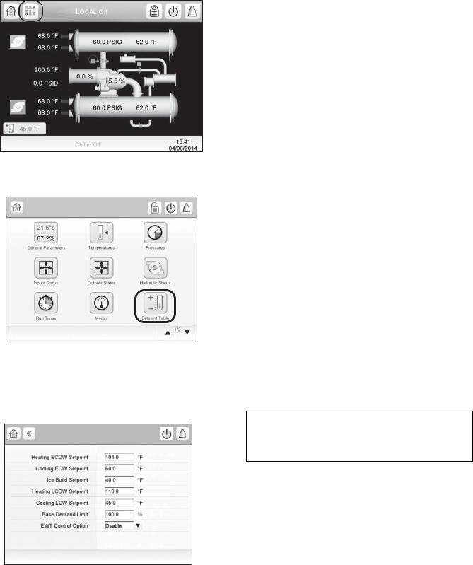
shown on pages CL-1 to CL-8, provides a list for configuration values.
Input the Design Set Points — To access the set point screen, press the Main Menu icon on the home screen. See Fig. 13.
Fig. 13 — Main Menu Icon
The Main Menu screen is displayed. Press the Setpoint Table icon (Fig. 14).
Main Menu
Fig. 14 — Main Menu — Setpoint Table Icon
The Setpoint screen is displayed (see Fig. 15). Set the base demand limit set point, and either the LCW set point or the ECW set point. To set a value, press the appropriate set point, enter the value, and press OK. For more information, see the the 19XR with PIC 5 Controls Operation and Troubleshooting manual.
SETPOINT - Setpoint Table
Fig. 15 — Setpoint Table Screen
a19-2121
Input the Local Occupied Schedule — Access the schedule screen and set up the occupied time schedule according to the customer’s requirements. If no schedule is available, the default is factory set for 24 hours occupied, 7 days per week including holidays. The Schedule Menu as well as the Holiday Menu can be reached through the Configuration Menu (see Appendix A on page 88 for an overview of the available menus). When the control mode is LOCAL SCHEDULE, the chiller will be automatically started if the configured local schedule is occupied; it will be shut down by the unoccupied schedule, EMSTOP software point, STOP button on HMI screen, or remote emergency stop contact.
The Network Schedule should be configured if a CCN system is being installed. When control mode is NETWORK, the chiller can be started and stopped by the CHIL_S_S software point as written by other equipment through the network command and network schedule. The chiller can be shut down by EMSTOP software point and remote emergency stop contact.
For more information about setting time schedules, see the 19XR with PIC 5 Controls Operation and Troubleshooting manual.
Input Service Configurations — For specific values for the following configurations, refer to the chiller performance data or job-specific data sheet:
•password
•log in/logout
•input time and date
•service parameters
•equipment configuration
•automated control test
PASSWORD — The PIC 5 control system provides different levels of access: Basic access, User access, Advanced User/ Service access and Factory access. User access provides basic access to the chiller controls. Advanced User access has access to all Service tables, and Factory user has access to factory tables. The PIC 5 default password configurations are as follows:
•Basic: No password required
•User: 1111
•Advanced User / Service Access: 2222
•Factory: 4444
When accessing the SERVICE tables, a password must be entered. The password can be changed from the Configuration Menu. USER CONFIGURATION allows change of the User access password. SERVICE PARAMETERS allows change of the Advanced User/Service password, and FACTORY PARAMETERS allows change of the Factory password. Passwords must be from 1 to 5 digits (range from 1 to 65535).
IMPORTANT: Be sure to remember the password. Retain a copy for future reference. Without the password, access to the SERVICE menu will not be possible unless accessed by a Carrier representative.
LOGIN/LOGOUT — Press the lock icon on the home screen to enter the password. See Fig. 16.
20
Fig. 16 — Lock Icon
The User Login Screen is displayed. Enter the password on this screen. See Fig 17. The language and system of measurement can also be changed on this screen. For details, see the 19XR with PIC 5 Controls Operation and Troubleshooting guide.
INPUT TIME AND DATE — Set day and time and if applicable Holidays through MAIN MENU CONFIGURATION MENU DATE/TIME CONFIGURATION. See the Controls Operation and Troubleshooting guide for details. Because a schedule is integral to the chiller control sequence, the chiller will not start until the time and date have been set.
NOTE: The date format is MM-DD-YY for English units and DD-MM-YY for SI units.
User Login Screen
Fig. 17 — User Login Screen
MODIFY CONTROLLER IDENTIFICATION IF NECESSARY — The module address can be changed from the Configuration Menu. Change this address under CONTROL IDENTIFICATION for each chiller if there is more than one chiller at the jobsite. Write the new address on the HMI module for future reference.
CONFIGURE SERVICE TABLES — Access the SERVICE tables through MAIN MENU CONFIGURATION MENU to modify or view the job site parameters shown in Table 7. For details, see the 19XR with PIC 5 Controls Operation and Troubleshooting guide.
|
Table 7 — Job Site Parameters |
|
|
|
|
PARAMETER |
TABLE |
|
Starter Type |
CONF_ISM — Select 0 for full voltage, 1 for reduced voltage, 2 for solid state, or 3 for freestanding variable |
|
frequency drive. |
||
|
||
Motor Rated Line Voltage |
CONF_ISM — Motor rated voltage from chiller information nameplate. |
|
Volt Transformer Ratio |
CONF_ISM — Enter ratio (reduced to a ratio to 1) of power transformer wired to terminal J3 of ISM. If no transformer |
|
is used enter 1. |
||
|
||
Motor Rated Load Amps |
CONF_ISM — Per chiller nameplate data. RL AMPS on compressor nameplate. |
|
Motor Locked Rotor Trip |
CONF_ISM — Per chiller identification nameplate. |
|
Starter LRA Rating |
CONF_ISM — Enter value from nameplate in starter cabinet MAXIMUM FUSE. This value shall always be “9999” for |
|
Benshaw RediStart MX3 wye-delta and solid-state starters. |
||
|
||
Motor Current CT Ratio |
CONF_ISM — Enter ratio (reduced to a ratio to 1) of current transformers wired to terminal J4 of ISM. This value shall |
|
always be “100” for Benshaw RediStart MX3 and solid-state starters. |
||
|
||
Current % Imbalance |
CONF_ISM — Current imbalance trip threshold. Enter up to 100% for starter type 3 (VFD). |
|
Ground Fault Current Transformers |
CONF_ISM — Enter 0 if no ground fault CTs are wired to terminal J5 of ISM. Enter 1 if ground fault CTs are used. |
|
Ground Fault CT Ratio |
CONF_ISM — Enter ratio (reduced to a ratio to 1) of ground fault CT. |
|
Single Cycle Dropout |
CONF_ISM — ENABLE if motor protection required from drop in line voltage within one cycle. |
|
Line Frequency |
CONF_ISM — Enter YES for 60 Hz or NO for 50 Hz. |
|
Line Frequency Faulting |
CONF_ISM — ENABLE if motor protection required for drop in line frequency. |
|
Hot Gas Bypass Option |
CONF_OPT — 1 = HGBP for Surge Correction; 2 = HGBP for Low Load Operation; 3 = Combination HGBP; 0 = no |
|
HGBP or HGBP is Disabled. |
||
|
||
Minimum Load Points (Tsmin, IGVmin) |
CFGSURGE — Per job data — See modify load points section. Refer to table located in the control panel. |
Full (Maximum) Load Points (Tsmax, IGVmax) CFGSURGE — Chiller Requisition (TSmin, IGV min) or per job data — See modify load points section. Refer to table located in the control panel.
Surge Line Shape Factor (shapefac) |
CFGSURGE — Per Chiller Requisition (shapefac). Refer to table located in the control panel. |
|
Chilled Medium |
FACTORY — Enter water or brine. |
|
Evaporator Refrigerant Trippoint |
CFGLIMIT — Usually 3° F (1.7° C) below design refrigerant temperature. |
|
Evaporator Flow Delta P Cutout |
CFGLIMIT — Per Chiller Requisition if available or enter 50% of design pressure drop to 0.5 psi (3.4 kPa).* |
|
Condenser Flow Delta P Cutout |
CFGLIMIT — Per Chiller Requisition if available or enter 50% of design pressure drop to 0.5 psi (3.4 kPa).* |
|
High Condenser Water Delta P |
CFGLIMIT — Enter the maximum allowable value for condenser water pressure drop. |
|
Motor Rated Kilowatts |
FACTORY — Enter value from chiller requisition form (product data submittal) if DEMAND LIMIT SOURCE is set to |
|
kW. |
||
|
*With variable flow systems this point may be configured to the lower end of the range.
NOTE: Other parameters: Screens are normally left at the default settings; they may be changed as required. The time and persistence settings on the CONF_ISM table can be adjusted to increase or decrease the sensitivity to a fault condition. Increasing time or persistence decreases sensitivity. Decreasing time or persistence increases sensitivity to the fault condition.
21
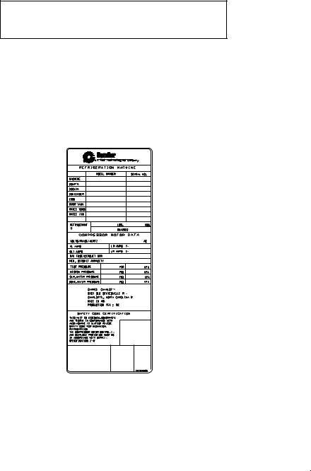
Field Set Up and Verification
IMPORTANT: Some parameters are specific to the chiller configuration and will need to be verified prior to operation. All command functions must be initiated from the HMI.
Use the HMI touch screen to confirm that the ISM values match the chiller paramter labels and Chiller Builder design data sheet. The ISM values can be located from MAIN MENUCONFIGURATION MENU ISM CONFIGURATION.
LABEL LOCATIONS — Verify the following labels have been installed properly and match the chiller requisition:
•Surge Parameters — Located inside the chiller control panel.
•Chiller identification nameplate — Located on the right side of the control panel. (See Fig. 18.)
TM |
A United Technologies Company |
||
REFRIGERATION MACHINE |
|
||
|
MODEL NUMBER |
SERIAL NO. |
|
MACHINE |
|
|
|
COMP'R |
|
|
|
COOLER |
|
|
|
CONDENSER |
|
|
|
ECON |
|
|
|
STOR TANK |
|
|
|
RATED TONS |
|
|
|
RATED iKW |
|
|
|
REFRIGERANT |
|
LBS. |
KGS. |
R- |
|
CHARGED |
|
|
|
||
COMPRESSOR MOTOR DATA |
|
||
VOLTS/PHASE/HERTZ |
|
AC |
|
RL AMPS |
|
LR AMPS |
Y- |
OLT AMPS |
|
LR AMPS D- |
|
MAX FUSE/CIRCUIT BKR |
|
|
|
MIN. CIRCUIT AMPACITY |
|
|
|
TEST PRESSURE |
|
PSI |
KPA |
DESIGN PRESSURE |
|
PSI |
KPA |
CLR.WATER PRESSURE |
PSI |
KPA |
|
COND.WATER PRESSURE |
PSI |
KPA |
|
CARRIER CHARLOTTE

9701 OLD STATESVILLE ROAD
 CHARLOTTE, NORTH CAROLINA 28269
 MADE IN USA
PRODUCTION YEAR: 20XX
20XX 

SAFETY CODE CERTIFICATION
THIS UNIT IS DESIGNED,CONSTRUCTED, 


AND TESTED IN CONFORMANCE WITH
ANSI/ASHRAE 15 (LATEST REVISION),

SAFETY CODE FOR MECHANICAL
REFRIGERATION. 
THE COMPRESSOR MOTOR CONTROLLER


AND OVERLOAD PROTECTION MUST BE
IN ACCORDANCE WITH CARRIER 


SPECIFICATION Z-415. 
a19-1881
19XR05009801
CHILLER ID NAMEPLATE — CONSTANT SPEED CHILLER
Fig. 18 — Machine Identification Nameplate
STARTER/DRIVE PROTECTION AND OTHER INCOMING WIRING
1.Verify that the branch disconnects or other local disconnects are open and properly tagged out.
2.Verify that the branch circuit protection and AC input wiring to the starter are in accordance with NEC/CEC (National Electrical Code/California Energy Commission) and all other local codes.
3.Verify that the fuses are per the field wiring diagram.
4.Verify that the incoming source does not exceed the SCCR (short circuit current rating) of the equipment marking.
5.Verify the power lugs in the starter/VFD and branch protection are properly secured. Inspect the ground cable and ensure it is properly connected at the branch and to the ground lug in the starter.
6.Verify the conduit for the power wiring in securely connected to the starter flanged cover and runs continuously to the branch protection.
7.Ensure the control and signal wires connected to the chiller controller or the starter/VFD are in separate conduits.
FINE TUNING VPF (VARIABLE PRIMARY FLOW) SURGE PREVENTION — Figures 19-22 show how the parameters defined below will affect the configured surge line. The menu can be found under MAIN MENU CONFIGURATION MENU SURGE CORRECTION CONFIG.
NOTE: Before tuning surge prevention, check for VFD (variable frequency drive) speed limitation or capacity overrides. If the source of low capacity is found in one of these places, do not proceed with an attempt to tune the Surge Prevention configurations.
If capacity is not reached and
1.ACTUAL GUIDE VANE POSITION < GUIDE VANE TRAVEL RANGE
and
2.SURGE PREVENTION ACTIVE = YES (can be identified in MAIN MENU MAINTENANCE MENU SURGE CORRECTION)
and
3. PERCENT LINE CURRENT < 100%
then the surge line is probably too conservative.
Note the following parameters from HMI when maximum ACTUAL LINE CURRENT achieved:
•EVAPORATOR REFRIGERANT TEMP
•EVAPORATOR PRESSURE
•CONDENSER REFRIG TEMP
•CONDENSER PRESSURE
•ACTUAL GUIDE VANE POSITION
•ACTUAL LINE CURRENT
The ACTIVE DELTA Tsat and the CALC REF DELTA TSAT can be monitored on the MAINTENANCE MENU SURGE CORRECTION screen. When DELTA TSAT exceeds CALC REF DELTA TSAT + ENVELOPE LINE OFFSET surge prevention will occur.
If ACTUAL GUIDE VANE POSITION is less than 30%, then increase SURGE DELTA TSMIN in steps of 2º F (1.2º C) until one of the three conditions listed above no longer applies. Do not change SURGE DELTA TSMAX.
If ACTUAL GUIDE VANE POSITION is greater than 60%, then increase SURGE DELTA TSMAX in steps of 2º F (1.2º C) until cooling capacity is reached or one of conditions listed above no longer applies. Do not change SURGE/HGBP DELTA TSMIN.
If ACTUAL GUIDE VANE POSITION is more than 30% AND less than 60%, then:
1.Increase SURGE DELTA TSMIN in steps of 2º F (1.2º C).
2.Increase SURGE DELTA TSMAX in steps of 2º F (1.2º C).
3.Repeat Steps 1 and 2 until one of the conditions listed above no longer applies.
NOTE: DELTA TSMIN should seldom need to be increased more than 10 degrees above the selection program value. Likewise, DELTA TSMAX rarely requires more than a 2º F (1.2º C) increase.
If surge is encountered then the surge line is probably too optimistic or high. Note following parameters from HMI at surge:
•EVAPORATOR REFRIGERANT TEMP
•EVAPORATOR PRESSURE
•CONDENSER REFRIG TEMP
•CONDENSER PRESSURE
•ACTUAL GUIDE VANE POSITION
•AVERAGE LINE CURRENT
22
40
35
|
30 |
|
|
|
|
|
|
|
|
|
|
|
|
Tsmin=30 |
|
25 |
|
|
|
|
|
|
|
|
|
|
|
|
|
Tsat |
20 |
|
|
|
|
|
|
|
|
|
|
|
|
Tsmin=40 |
Delta |
|
|
|
|
|
|
|
|
|
|
|
|
||
|
|
|
|
|
|
|
|
|
|
|
|
|
||
|
|
|
|
|
|
|
|
|
|
|
|
|
|
|
|
15 |
|
|
|
|
|
|
|
|
|
|
|
|
|
|
|
|
|
|
|
|
|
|
|
|
|
|
|
Tsmin=50 |
|
10 |
|
|
|
|
|
|
|
|
|
|
|
|
|
|
5 |
|
|
|
|
|
|
|
|
|
|
|
|
|
|
0 |
|
|
|
|
|
|
|
|
|
|
|
|
|
|
|
|
|
|
|
|
|
|
|
|
|
|
|
|
|
0 |
10 |
20 |
30 |
40 |
50 |
60 |
70 |
80 |
90 |
100 |
110 |
||
GV_POS
a19-1959
Fig. 19 — Effect of SURGE DELTA TSMIN on Surge Prevention
|
45 |
|
40 |
|
35 |
|
Tsmax=60 |
|
30 |
Tsat |
25 |
Delta |
Tsmax=70 |
20 |
15
 Tsmax=80
10
5
0
0 |
10 |
20 |
30 |
40 |
50 |
60 |
70 |
80 |
90 |
100 |
110 |
GV_POS
a19-1960
Fig. 20 — Effect of SURGE DELTA TSMAX on Surge Prevention
|
60.00 |
|
|
|
|
|
|
|
|
|
|
|
|
55.00 |
|
|
|
|
|
|
|
|
|
|
|
|
50.00 |
|
|
|
|
|
|
|
|
|
|
|
|
45.00 |
|
|
|
|
|
|
|
|
|
|
Shape factor |
|
|
|
|
|
|
|
|
|
|
|
|
= -0.020 |
|
40.00 |
|
|
|
|
|
|
|
|
|
|
|
Tsat |
35.00 |
|
|
|
|
|
|
|
|
|
|
|
|
|
|
|
|
|
|
|
|
|
|
Shape factor |
|
|
|
|
|
|
|
|
|
|
|
|
|
|
Delta |
30.00 |
|
|
|
|
|
|
|
|
|
|
= -0.040 |
25.00 |
|
|
|
|
|
|
|
|
|
|
|
|
|
|
|
|
|
|
|
|
|
|
|
|
|
|
20.00 |
|
|
|
|
|
|
|
|
|
|
Shape factor |
|
|
|
|
|
|
|
|
|
|
|
|
= -0.050 |
|
15.00 |
|
|
|
|
|
|
|
|
|
|
|
|
10.00 |
|
|
|
|
|
|
|
|
|
|
|
|
5.00 |
|
|
|
|
|
|
|
|
|
|
|
|
0.00 |
|
|
|
|
|
|
|
|
|
|
|
|
0 |
10 |
20 |
30 |
40 |
50 |
60 |
70 |
80 |
90 |
100 |
110 |
GV_POS
a19-1961
Fig. 21 — Effect of SURGE LINE SHAPE FACTOR on Surge Prevention
|
40.00 |
|
|
|
|
|
|
|
|
|
|
|
|
35.00 |
|
|
|
|
|
|
|
|
|
|
|
|
30.00 |
|
|
|
|
|
|
|
|
|
|
Speed Factor |
|
|
|
|
|
|
|
|
|
|
|
|
=1.60 |
Tsat |
25.00 |
|
|
|
|
|
|
|
|
|
|
|
|
|
|
|
|
|
|
|
|
|
|
Speed Factor |
|
|
|
|
|
|
|
|
|
|
|
|
|
|
Delta |
20.00 |
|
|
|
|
|
|
|
|
|
|
=1.85 |
|
|
|
|
|
|
|
|
|
|
|
|
|
|
15.00 |
|
|
|
|
|
|
|
|
|
|
|
|
|
|
|
|
|
|
|
|
|
|
|
Speed Factor |
|
|
|
|
|
|
|
|
|
|
|
|
=2.00 |
|
10.00 |
|
|
|
|
|
|
|
|
|
|
|
|
5.00 |
|
|
|
|
|
|
|
|
|
|
|
|
0.00 |
|
|
|
|
|
|
|
|
|
|
|
|
0 |
10 |
20 |
30 |
40 |
50 |
60 |
70 |
80 |
90 |
100 |
110 |
GV_POS
a19-1962
Fig. 22 — Effect of SURGE LINE SPEED FACTOR on Surge Prevention
If ACTUAL GUIDE VANE POSITION is less than 30%, go to Step 1. If ACTUAL GUIDE VANE POSITION is greater than 60%, then go to Step 3.
1.Do not change SURGE LINE SHAPE FACTOR from the value selected by Chiller Builder (ECAT). Decrease SURGE DELTA TSMIN in 1° F steps up to 5 times. Monitor chiller for surge.
2.If ACTUAL GUIDE VANE POSITION is still less than 30 and Step 1 failed, then increase the value of SURGE LINE SHAPE FACTOR in steps of 0.01 up to 2 times. For example, if surge is encountered when shape factor is –0.06, increase the SURGE LINE SHAPE FACTOR to –0.05. If this does not solve the problem, go to Step 5, even if ACTUAL GUIDE VANE POSITION is less than 30%.
3.Do not change SURGE LINE SHAPE FACTOR from the value selected by Chiller Builder (ECAT). Decrease SURGE DELTA TSMAX by 1° F steps up to 5 times. Monitor chiller for surge.
4.If ACTUAL GUIDE VANE POSITION is greater than 60% and Step 3 failed to eliminate surge, then set SURGE DELTA TSMAX to 5° F below the value specified by Chiller Builder (ECAT). Increase the value of the SURGE LINE SHAPE FACTOR in steps of 0.01 up to 2 times. For example, if surge is encountered when the SURGE LINE SHAPE FACTOR is –0.06, increase the SURGE LINE SHAPE FACTOR to –0.05. If this does not solve the problem, go to Step 5, even if ACTUAL GUIDE VANE POSITION is greater than 60%.
5.If ACTUAL GUIDE VANE POSITION is greater than 30% but less than 60% or if Step 2 failed (with ACTUAL GUIDE VANE POSITION less than 30) or if Step 4 failed (with ACTUAL GUIDE VANE POSITION greater than 60), then perform this step. Do not change SURGE LINE SHAPE FACTOR from the value specified by Chiller Builder (ECAT). Reset SURGE DELTA TSMIN and SURGE DELTA TSMAX to the value specified by Chiller Builder (ECAT). Decrease SURGE DELTA TSMIN and SURGE DELTA TSMAX in steps of 1° F up to 5 times. Monitor chiller for surge.
If the chiller is equipped with a VFD and the drive does not slow down adequately at part load, then the machine is likely operating at a point above the configured “software” surge line and the machine is in surge prevention mode. Check for a surge protection message on the HMI. If the unit is not in a surge protection state, then the ENVELOPE SPEED FACTOR may
23

need to be increased (more aggressive surge line protection) in combination with a decrease in the SURGE LINE SHAPE FACTOR.
MODIFY EQUIPMENT CONFIGURATION IF NECESSARY — The EQUIPMENT SERVICE table has screens to select, view, or modify parameters. Carrier’s certified drawings have the configuration values required for the jobsite. Modify these values only if requested. Modifications can include:
•Chilled water reset
•Entering chilled water control (Enable/Disable)
•4 to 20 mA demand limit
•Auto restart option (Enable/Disable)
•Remote contact option (Enable/Disable)
See the 19XR with PIC 5 Controls Operation and Troubleshooting guide for more details about these functions.
Perform a Controls Test (Quick Test) — Check the safety controls status by performing an automated controls test. The path to the QUICK TEST is MAIN MENU QUICK TEST TABLE. (The QUICK TEST screen can only be accessed when the chiller is in STOP mode.) On the
QUICK TEST table screen, select a test to be performed (see Table 8).
The Quick Test checks all outputs and inputs for function. In order to successfully proceed with the controls test, the compressor should be off, no alarms showing, and voltage should be within ±10% of rating plate value. Each test asks the operator to confirm the operation is occurring and whether or not to continue. If an error occurs, the operator can try to address the problem as the test is being done or note the problem and proceed to the next test.
NOTE: If during the controls test the guide vanes do not open, verify the low pressure alarm is not active. (An active low pressure alarm causes the guide vanes to close.)
NOTE: The oil pump test will not energize the oil pump if cooler pressure is below –5 psig (–35 kPa).
When the controls test is finished the test stops and the QUICK TEST menu displays. If a specific automated test procedure is not completed, access the particular control test to test the function when ready. For information about calibration, see the sections Checking Pressure Transducers, page 46, and High Altitude Locations, page 46.
Table 8 — Quick Test Table
CCN TABLE NAME: QCK_TEST
PIC 5 PATH: Main Menu Quick Test
LINE |
PIC 5 DESCRIPTION |
CCN NAME |
RANGE |
DEFAULT |
UNIT |
READ/WRITE |
|
VALUE* |
|||||||
|
|
|
|
|
|
||
1 |
Quick Test Enable |
QCK_TEST |
DSABLE/ENABLE |
DSABLE |
|
RW |
|
2 |
GV 1 Calibration Enable |
GV1_CAL |
DSABLE/ENABLE |
DSABLE |
|
RW |
|
3 |
GV1 Calibration Status |
GV1_STAT |
0 to 2 |
|
|
RO |
|
|
0=No Calibration or Failure |
|
|
|
|
|
|
|
1=In Progress, 2=Completed |
|
|
|
|
|
|
4 |
Guide Vane 1 Actual Ohms |
GV1_OHM |
0.00 to 12000.00 |
|
|
RO |
|
5 |
Guide Vane 1 Actual mA |
GV1_MAF |
0.0 to 20.8 |
|
mA |
RO |
|
6 |
Guide Vane 1 Forced Position |
Q_GV1POS |
0.0 to 100.0 |
0.0 |
% |
RW |
|
7 |
Quick Test GV1 Open |
Q_GV1OP |
OFF/ON |
OFF |
|
RW |
|
8 |
Quick Test GV1 Close |
Q_GV1CL |
OFF/ON |
OFF |
|
RW |
|
9 |
Quick Test Oil Pump |
Q_OILP |
OFF/ON |
OFF |
|
RW |
|
10 |
Oil Pres Test Passed |
OP_PASS |
NO/YES |
|
|
RO |
|
11 |
Oil Pump Delta Pressure |
OIL_PDQ |
–6.7 to 420.0 |
|
psig |
RO |
|
12 |
Quick Test Oil Heater |
Q_OILH |
OFF/ON |
OFF |
|
RW |
|
13 |
Quick Test HGBP Open |
Q_HGBPOP |
OFF/ON |
OFF |
|
RW |
|
14 |
Quick Test HGBP Close |
Q_HGBPCL |
OFF/ON |
OFF |
|
RW |
|
15 |
Quick Test Damper Open |
Q_DMPOP |
OFF/ON |
OFF |
|
RW |
|
16 |
Quick Test Damper Close |
Q_DMPCL |
OFF/ON |
OFF |
|
RW |
|
17 |
Quick Test Cond Pump |
Q_CDWP |
OFF/ON |
OFF |
|
RW |
|
18 |
Condenser Water Flow |
CDW_FLOW |
NO/YES |
|
|
RO |
|
19 |
Quick Test Chilled Pump |
Q_CHWP |
OFF/ON |
OFF |
|
RW |
|
20 |
Chileld Water Flow |
CHW_FLOW |
NO/YES |
|
|
RO |
|
21 |
Condenser Water Flow |
CDW_FLOW |
NO/YES |
|
|
RO |
|
22 |
Chilled Water Flow |
CHW_FLOW |
NO/YES |
|
|
RO |
|
23 |
Quick Test Head Val Pos |
Q_HDP |
0.0 to 100.0 |
0.0 |
% |
RW |
|
24 |
Quick Test Diffuser Pos |
Q_SRD |
0.0 to 100.0 |
0.0 |
% |
RW |
|
25 |
Quick Test Chiller Status |
Q_CHST |
4.0 to 20.0 |
4.0 |
mA |
RW |
|
26 |
Quick Test Oil EXV |
Q_EXV |
4.0 to 20.0 |
4.0 |
mA |
RW |
|
27 |
Condenser Water Delta T |
CDW_DT |
–40.0 to 245.0 |
|
°F |
RO |
|
28 |
Chilled Water Delta T |
CHW_DT |
–40.0 to 245.0 |
|
°F |
RO |
|
29 |
Cond Water Deviation |
CDWT_DV |
OFF/ON |
|
|
RO |
|
30 |
Chilled Water Deviation |
CHWT_DV |
OFF/ON |
|
|
RO |
|
31 |
Quick Test Alarm Output |
Q_ALM |
OFF/ON |
OFF |
|
RW |
|
32 |
Quick Test Alert Output |
Q_ALE |
OFF/ON |
OFF |
|
RW |
|
33 |
Guide Vane 1 Ohms 100% |
GV1_MAXO |
0.00 to 12000.00 |
|
|
RO |
|
34 |
Guide Vane 1 Ohms 0% |
GV1_MINO |
0.00 to 12000.00 |
|
|
RO |
|
35 |
Guide Vane 1 mA 100% |
GV1_MAXA |
0.0 to 20.8 |
|
mA |
RO |
|
36 |
Guide Vane 1 mA 0% |
GV1_MINA |
0.0 to 20.8 |
|
mA |
RO |
|
LEGEND |
NOTES: |
||
GV |
— Guide Vane |
1. |
Quick Test ENABLE defaults back to DISABLE after 1 hour. |
|
2. |
During any of the tests, an out-of-range reading will have an asterisk (*) |
|||
HGBP — Hot Gas Bypass |
||||
|
next to the reading and a message will be displayed if the diffuser control |
|||
RO |
— Read Only |
|
||
|
is enabled. |
|||
RW |
— Read Write |
|
||
|
|
|||
*Default value is shown only if configurable in this table.
24
Charge Refrigerant into Chiller
CAUTION
The transfer, addition, or removal of refrigerant in spring isolated chillers may place severe stress on and damage external piping if springs have not been blocked in both up and down directions.
CAUTION
Always operate the condenser and chilled water pumps during charging operations to prevent freeze-ups.
The standard 19XR chiller is shipped with the refrigerant already charged in the vessels. However, the 19XR chiller may be ordered with a nitrogen holding charge of 15 psig (103 kPa). Evacuate the nitrogen from the entire chiller, and charge the chiller from refrigerant cylinders.
CHILLER EQUALIZATION WITHOUT A PUMPOUT UNIT
CAUTION
When equalizing refrigerant pressure on the 19XR chiller after service work or during the initial chiller start-up, do not use the discharge isolation valve to equalize. A charging hose (connected between the charging valves on top of the cooler and condenser) should be used as the equalization valve. Failure to follow this procedure may damage equipment.
To equalize the pressure differential on a refrigerant isolated 19XR chiller, use the terminate lockout function of PUMPDOWN/LOCKOUT (located in the Maintenance Menu). This helps to turn on pumps and advises the operator on proper procedures.
The following steps describe how to equalize refrigerant pressure in an isolated 19XR chiller without a pumpout unit.
1.Access terminate lockout function on the Maintenance Menu. (Alternatively, the Quick Test provides a means for cooler and condenser pump control.)
2.IMPORTANT: Turn on the chilled water and condenser water pumps to prevent freezing.
3.Slowly open the refrigerant charging valves. The chiller cooler and condenser pressures will gradually equalize. This process takes approximately 15 minutes.
4.Once the pressures have equalized, the cooler isolation valve, the condenser isolation valve, and the hot gas isolation valve may now be opened. Refer to Fig. 23 and 24 for the location of the valves.
WARNING 
Whenever turning the discharge isolation valve, be sure to reattach the valve locking device. This prevents the valve from opening or closing during service work or during chiller operation. Failure to follow this procedure may damage equipment and result in bodily injury.
CHILLER EQUALIZATION WITH FREE-STANDING PUMPOUT UNIT — The following steps describe how to equalize refrigerant pressure on an isolated 19XR chiller using the pumpout unit.
1.Access the terminate lockout function on the PUMPDOWN/LOCKOUT screen (located in the Maintenance Menu).
2.IMPORTANT: Turn on the chilled water and condenser water pumps to prevent freezing.
3.Open valve 4 on the pumpout unit and open valves 1a and 1b on the chiller cooler and condenser, Fig. 23 and 24. Slowly open valve 2 on the pumpout unit to equalize the pressure. This process takes approximately 15 minutes.
4.Once the pressures have equalized, the discharge isolation valve, cooler isolation valve, optional hot gas bypass isolation valve, and the refrigerant isolation valve can be opened. Close valves 1a and 1b, and all pumpout unit valves.
 WARNING
Whenever turning the discharge isolation valve, be sure to reattach the valve locking device. This prevents the valve from opening or closing during service work or during chiller operation. Failure to follow this procedure may damage equipment and result in bodily injury.
The full refrigerant charge on the 19XR chiller will vary with chiller components and design conditions, as indicated on the job data specifications. An approximate charge may be determined by adding the condenser charge to the cooler charge as listed in the Heat Exchanger Data tables in the Physical Data section that begins on page 48.
 CAUTION
Always operate the condenser and chilled water pumps whenever charging, transferring, or removing refrigerant from the chiller. Always confirm that water flow is established. Failure to follow this procedure may result in equipment damage.
Use the PUMPDOWN/LOCKOUT terminate lockout function to monitor conditions and start the pumps.
If the chiller has been shipped with a holding charge, the refrigerant is added through the pumpout charging connection (Fig. 23 and 24, valve 1b). First evacuate the nitrogen holding charge from the chiller vessels. Charge the refrigerant as a gas until the system pressure exceeds 35 psig (241 kPa) for HFC134a. After the chiller is beyond this pressure the refrigerant should be charged as a liquid until all the recommended refrigerant charge has been added. The charging valve (Fig. 23 and 24, valve 7) can be used to charge liquid to the cooler if the cooler isolation valve (11) is present and is closed. Do not charge liquid through the linear float to the condenser.
TRIMMING REFRIGERANT CHARGE — The 19XR chiller is shipped with the correct charge for the design duty of the chiller. Trimming the charge can best be accomplished when the design load is available. To trim the charge, check the temperature difference between the leaving chilled water temperature and cooler refrigerant temperature at full load design conditions. If necessary, add or remove refrigerant to bring the temperature difference to design conditions or minimum differential. See the 19XR Installation Instructions manual for required chiller refrigerant charge.
The 19XR chiller refrigerant charges are shown in Tables 9 and 10. Total refrigerant charge is the sum of the cooler, condenser, and economizer charge.
25
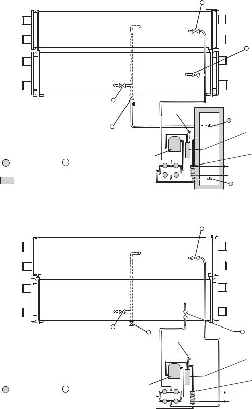
|
|
|
|
1b |
REFRIGERANT |
|
|
|
|
|
CHARGING VALVE |
|
CHILLER |
|
|
|
|
|
CONDENSER |
|
|
|
|
|
VESSEL |
|
|
|
|
|
|
|
|
|
1a REFRIGERANT |
|
|
|
|
|
CHARGING VALVE |
|
CHILLER |
|
|
|
|
|
COOLER |
|
|
|
|
|
VESSEL |
|
|
|
|
|
COOLER 11 |
TEE FOR |
|
|
|
|
REFRIGERANT |
|
|
|
|
|
CHARGING |
PRESSURE |
|
||
|
ISOLATION |
|
|||
|
|
|
|||
|
|
RELIEF SAFETY |
|
||
|
VALVE |
|
STORAGE |
||
|
|
VALVE |
|
||
|
|
|
|
||
|
|
|
|
|
10 TANK LIQUID |
|
7 |
|
|
|
VALVE |
|
|
|
|
OIL |
|
|
LIQUID LINE |
|
|
|
|
|
|
|
|
SEPARATOR |
|
|
SERVICE |
|
|
|
|
|
|
|
|
|
|
|
VALVE |
|
|
|
|
|
|
PUMPOUT |
|
|
PUMPOUT |
|
|
COMPRESSOR |
|
|
CONDENSER |
= SERVICE VALVE ON |
= SERVICE VALVE ON |
|
2 |
|
PUMPOUT |
PUMPOUT UNIT |
CHILLER (FIELD |
|
3 |
||
|
SUPPLIED) |
|
|
|
CONDENSER |
|
|
|
4 |
5 |
WATER SUPPLY |
= MAINTAIN AT LEAST 2 FT (610mm) CLEARANCE AROUND |
|
|
AND RETURN |
||
STORAGE TANK FOR SERVICE AND OPERATION WORK. |
|
|
6 STORAGE TANK a19-1721 |
||
|
|
|
|
|
VAPOR VALVE |
Fig. 23 — Typical Optional Pumpout System Piping Schematic with Storage Tank
REFRIGERANT 1b CHARGING
VALVE
CHILLER
CONDENSER
VESSEL
CHILLER
COOLER
VESSEL
COOLER 11 |
|
|
|
REFRIGERANT |
7 |
PRESSURE |
|
ISOLATION |
LIQUID LINE |
||
RELIEF SAFETY |
|||
VALVE |
SERVICE |
||
VALVE |
|||
|
VALVE |
||
|
|
|
= SERVICE VALVE ON |
PUMPOUT |
|
= SERVICE VALVE ON |
COMPRESSOR |
|
|
PUMPOUT UNIT |
CHILLER |
2 |
3 |
|
|
4 |
5 |
REFRIGERANT 1a CHARGING
VALVE
OIL
SEPARATOR
PUMPOUT
CONDENSER
PUMPOUT
CONDENSER
WATER SUPPLY
AND RETURN a19-1722
Fig. 24 — Typical Freestanding Pumpout System Piping Schematic without Storage Tank
26
Table 9 — 19XR Two-Stage Compressor Frame Size 6 Heat Exchanger Refrigerant Charge
|
|
ENGLISH |
|
|
|
SI |
|
|
CODE* |
|
MACHINE CHARGE |
|
|
MACHINE CHARGE |
|
||
|
REFRIGERANT WEIGHT (lb) |
|
REFRIGERANT WEIGHT (kg) |
|||||
|
|
|
||||||
|
COOLER ONLY |
CONDENSER ONLY |
ECONOMIZER ONLY |
COOLER ONLY |
|
CONDENSER ONLY |
|
ECONOMIZER ONLY |
A40 |
1647 |
927 |
360 |
747 |
|
420 |
|
163 |
A41 |
1773 |
927 |
360 |
804 |
|
420 |
|
163 |
A42 |
1887 |
927 |
360 |
856 |
|
420 |
|
163 |
A45 |
1599 |
927 |
360 |
725 |
|
420 |
|
163 |
A46 |
1714 |
927 |
360 |
777 |
|
420 |
|
163 |
A47 |
1837 |
927 |
360 |
833 |
|
420 |
|
163 |
|
|
|
|
|
|
|
|
|
A60 |
1878 |
1074 |
360 |
852 |
|
487 |
|
163 |
A61 |
2022 |
1074 |
360 |
917 |
|
487 |
|
163 |
A62 |
2152 |
1074 |
360 |
976 |
|
487 |
|
163 |
A65 |
1823 |
1074 |
360 |
827 |
|
487 |
|
163 |
A66 |
1954 |
1074 |
360 |
886 |
|
487 |
|
163 |
A67 |
2095 |
1074 |
360 |
950 |
|
487 |
|
163 |
|
|
|
|
|
|
|
|
|
A4A |
1681 |
861 |
360 |
762 |
|
391 |
|
163 |
A4B |
1792 |
861 |
360 |
813 |
|
391 |
|
163 |
A4C |
1897 |
861 |
360 |
860 |
|
391 |
|
163 |
A4F |
1626 |
861 |
360 |
738 |
|
391 |
|
163 |
A4G |
1736 |
861 |
360 |
787 |
|
391 |
|
163 |
A4H |
1890 |
861 |
360 |
857 |
|
391 |
|
163 |
|
|
|
|
|
|
|
|
|
A6A |
1917 |
998 |
360 |
870 |
|
453 |
|
163 |
A6B |
2044 |
998 |
360 |
927 |
|
453 |
|
163 |
A6C |
2164 |
998 |
360 |
982 |
|
453 |
|
163 |
A6F |
1854 |
998 |
360 |
841 |
|
453 |
|
163 |
A6G |
1979 |
998 |
360 |
898 |
|
453 |
|
163 |
A6H |
2156 |
998 |
360 |
978 |
|
453 |
|
163 |
|
|
|
|
|
|
|
|
|
B40 |
— |
1233 |
360 |
— |
|
559 |
|
163 |
B41 |
— |
1233 |
360 |
— |
|
559 |
|
163 |
B42 |
— |
1233 |
360 |
— |
|
559 |
|
163 |
B45 |
— |
1233 |
360 |
— |
|
559 |
|
163 |
B46 |
— |
1233 |
360 |
— |
|
559 |
|
163 |
B47 |
— |
1233 |
360 |
— |
|
559 |
|
163 |
|
|
|
|
|
|
|
|
|
B60 |
— |
1423 |
360 |
— |
|
645 |
|
163 |
B61 |
— |
1423 |
360 |
— |
|
645 |
|
163 |
B62 |
— |
1423 |
360 |
— |
|
645 |
|
163 |
B65 |
— |
1423 |
360 |
— |
|
645 |
|
163 |
B66 |
— |
1423 |
360 |
— |
|
645 |
|
163 |
B67 |
— |
1423 |
360 |
— |
|
645 |
|
163 |
|
|
|
|
|
|
|
|
|
B4A |
— |
1148 |
360 |
— |
|
521 |
|
163 |
B4B |
— |
1148 |
360 |
— |
|
521 |
|
163 |
B4C |
— |
1148 |
360 |
— |
|
521 |
|
163 |
B4F |
— |
1148 |
360 |
— |
|
521 |
|
163 |
B4G |
— |
1148 |
360 |
— |
|
521 |
|
163 |
B4H |
— |
1148 |
360 |
— |
|
521 |
|
163 |
|
|
|
|
|
|
|
|
|
B6A |
— |
1326 |
360 |
— |
|
601 |
|
163 |
B6B |
— |
1326 |
360 |
— |
|
601 |
|
163 |
B6C |
— |
1326 |
360 |
— |
|
601 |
|
163 |
B6F |
— |
1326 |
360 |
— |
|
601 |
|
163 |
B6G |
— |
1326 |
360 |
— |
|
601 |
|
163 |
B6H |
— |
1326 |
360 |
— |
|
601 |
|
163 |
*See Model Number Nomenclature on page 5.
27
Table 10 — 19XR Two-Stage Compressor Frame Size 7 Heat Exchanger Refrigerant Charge
|
|
ENGLISH |
|
|
|
SI |
|
|
CODE* |
|
MACHINE CHARGE |
|
|
MACHINE CHARGE |
|
||
|
REFRIGERANT WEIGHT (lb) |
|
REFRIGERANT WEIGHT (kg) |
|||||
|
|
|
||||||
|
COOLER ONLY |
CONDENSER ONLY |
ECONOMIZER ONLY |
COOLER ONLY |
|
CONDENSER ONLY |
|
ECONOMIZER ONLY |
B60 |
2273 |
— |
646 |
1031 |
|
— |
|
293 |
B61 |
2355 |
— |
646 |
1068 |
|
— |
|
293 |
B62 |
2460 |
— |
646 |
1116 |
|
— |
|
293 |
B65 |
2185 |
— |
646 |
991 |
|
— |
|
293 |
B66 |
2275 |
— |
646 |
1032 |
|
— |
|
293 |
B67 |
2379 |
— |
646 |
1079 |
|
— |
|
293 |
|
|
|
|
|
|
|
|
|
B6A |
2081 |
— |
646 |
944 |
|
— |
|
293 |
B6B |
2162 |
— |
646 |
981 |
|
— |
|
293 |
B6C |
2256 |
— |
646 |
1023 |
|
— |
|
293 |
B6F |
1951 |
— |
646 |
885 |
|
— |
|
293 |
B6G |
2019 |
— |
646 |
916 |
|
— |
|
293 |
B6H |
2120 |
— |
646 |
962 |
|
— |
|
293 |
|
|
|
|
|
|
|
|
|
C60 |
2647 |
1610 |
646 |
1201 |
|
730 |
|
293 |
C61 |
2751 |
1610 |
646 |
1248 |
|
730 |
|
293 |
C62 |
2875 |
1610 |
646 |
1304 |
|
730 |
|
293 |
C65 |
2562 |
1610 |
646 |
1162 |
|
730 |
|
293 |
C66 |
2666 |
1610 |
646 |
1209 |
|
730 |
|
293 |
C67 |
2793 |
1610 |
646 |
1267 |
|
730 |
|
293 |
|
|
|
|
|
|
|
|
|
C6A |
2443 |
1497 |
646 |
1108 |
|
679 |
|
293 |
C6B |
2534 |
1497 |
646 |
1149 |
|
679 |
|
293 |
C6C |
2627 |
1497 |
646 |
1192 |
|
679 |
|
293 |
C6F |
2334 |
1497 |
646 |
1059 |
|
679 |
|
293 |
C6G |
2415 |
1497 |
646 |
1095 |
|
679 |
|
293 |
C6H |
2500 |
1497 |
646 |
1134 |
|
679 |
|
293 |
|
|
|
|
|
|
|
|
|
D60 |
— |
2097 |
646 |
— |
|
951 |
|
293 |
D61 |
— |
2097 |
646 |
— |
|
951 |
|
293 |
D62 |
— |
2097 |
646 |
— |
|
951 |
|
293 |
D65 |
— |
2097 |
646 |
— |
|
951 |
|
293 |
D66 |
— |
2097 |
646 |
— |
|
951 |
|
293 |
D67 |
— |
2097 |
646 |
— |
|
951 |
|
293 |
|
|
|
|
|
|
|
|
|
D6A |
— |
1947 |
646 |
— |
|
883 |
|
293 |
D6B |
— |
1947 |
646 |
— |
|
883 |
|
293 |
D6C |
— |
1947 |
646 |
— |
|
883 |
|
293 |
D6F |
— |
1947 |
646 |
— |
|
883 |
|
293 |
D6G |
— |
1947 |
646 |
— |
|
883 |
|
293 |
D6H |
— |
1947 |
646 |
— |
|
883 |
|
293 |
*See Model Number Nomenclature on page 5.
28
INITIAL START-UP Preparation — Before starting the chiller, verify:
1.Power is on to the main starter, oil pump relay, tower fan starter, oil heater relay, and the chiller control panel.
2.Cooling tower water is at proper level and at-or-below design entering temperature.
3.Chiller is charged with refrigerant and all refrigerant and oil valves are in their proper operating positions.
4.Oil is at the proper level in the reservoir sight glasses.
5.Oil reservoir temperature is above 140 F (60 C) or above CALC EVAP SAT TEMP plus 50 F (28 C).
6.Valves in the evaporator and condenser water circuits are open.
NOTE: If the pumps are not automatic, ensure water is circulating properly.
CAUTION
Do not permit water or brine that is warmer than 110 F (43 C) to flow through the cooler or condenser. Refrigerant overpressure may discharge through the relief valves and result in the loss of refrigerant charge.
7.Access the PUMPDOWN/LOCKOUT feature from the Maintenance Menu. Press the End Lockout button on the touch screen and accept the “press OK to Terminate Lockout?” prompt. The unit is reset to operating mode. The chiller is locked out at the factory in order to prevent accidental start-up.
Check Motor Rotation
1.Disengage the main starter disconnect and engage the control panel power circuit breaker.
NOTE: The circuit breaker may be located in the starter if the disconnect and step down transformer option was ordered with the starter. If located in the starter, close the door securely after this step.
2.Close the starter enclosure door.
3.The ISM (integrated starter module) mounted in the starter enclosure checks for proper phase rotation as soon as power is applied to the starter and the PIC 5 controls power up.
4.An alarm message will appear on the HMI screen if the phase rotation is incorrect. If this occurs reverse any 2 of the 3 incoming power leads to the starter and reapply power. The motor is now ready for a rotation check.
5.Start the chiller by Local On (assumes LOCAL operation mode) by pressing the Start/Stop button on the HMI and following the prompts. The PIC 5 control performs startup checks.
6.When the starter is energized and the motor begins to turn, check for clockwise motor rotation (Fig. 25).
IMPORTANT: Do not check motor rotation during coastdown. Rotation may have reversed during equalization of vessel pressures.
Check Oil Pressure and Compressor Stop
1.When the motor is at full speed, note the differential oil pressure reading on the HMI default screen. It should be between 18 and 40 psid (124 and 206 kPad). The oil pump will geenrate design oil pressure only with the correct electrical phasing of ABC.
2.Press the Stop button and listen for any unusual sounds from the compressor as it coasts to a stop.
Fig. 25 — Correct Motor Rotation
To Prevent Accidental Start-Up — A chiller STOP override setting may be entered to prevent accidental start-up during service or whenever necessary. From the Main Menu, access the General Parameters Menu and use the down arrow to reach Stop Override on the GENUNIT table. Change Stop Override to Yes; then execute the command by touching the lightning button. The message “ALM-276 Protective Limit - Stop Override” will appear in the Home Screen message area. To restart the chiller, access the same screen change the Stop Override option to No.
Check Chiller Operating Condition — Check to be sure that chiller temperatures, pressures, water flows, and oil and refrigerant levels indicate the system is functioning properly.
Instruct the Customer Operator — Ensure the operator(s) understand all operating and maintenance procedures. Point out the various chiller parts and explain their function as part of the complete system.
COOLER-CONDENSER — High side float chamber, relief valves, refrigerant charging valve, temperature sensor locations, pressure transducer locations, Schrader fittings, waterboxes and tubes, and vents and drains.
OPTIONAL PUMPOUT STORAGE TANK AND PUMPOUT SYSTEM — Transfer valves and pumpout system, refrigerant charging and pumpdown procedure, and relief devices.
MOTOR COMPRESSOR ASSEMBLY — Guide vane actuator, transmission, motor cooling system, oil cooling system, temperature and pressure sensors, oil sight glasses, integral oil pump, isolatable oil filter, extra oil and motor temperature sensors, synthetic oil, and compressor serviceability.
MOTOR COMPRESSOR LUBRICATION SYSTEM — Oil pump, cooler filter, oil heater, oil charge and specification, operating and shutdown oil level, temperature and pressure, and oil charging connections.
ECONOMIZER — Float valve, drain valve, Schrader fitting, damper valve.
CONTROL SYSTEM — CCN and LOCAL start, reset, menu, softkey functions, HMI operation, occupancy schedule, set points, safety controls, and auxiliary and optional controls.
AUXILIARY EQUIPMENT — Starters and disconnects, separate electrical sources, pumps, and cooling tower.
DESCRIBE CHILLER CYCLES — Refrigerant, motor cooling, lubrication, and oil reclaim.
29
REVIEW MAINTENANCE — Scheduled, routine, and extended shutdowns, importance of a log sheet, importance of water treatment and tube cleaning, and importance of maintaining a leak-free chiller.
SAFETY DEVICES AND PROCEDURES — Electrical disconnects, relief device inspection, and handling refrigerant.
CHECK OPERATOR KNOWLEDGE — Start, stop, and shutdown procedures, safety and operating controls, refrigerant and oil charging, and job safety.
REVIEW THE START-UP, OPERATION, AND MAINTENANCE MANUAL.
OPERATING INSTRUCTIONS
Operator Duties
1.Become familiar with the chiller and related equipment before operating the chiller.
2.Prepare the system for start-up, start and stop the chiller, and place the system in a shutdown condition.
3.Maintain a log of operating conditions and document any abnormal readings.
4.Inspect the equipment, make routine adjustments, and perform a Control Test. Maintain the proper oil and refrigerant levels.
5.Protect the system from damage during shutdown periods.
6.Maintain the set point, time schedules, and other PIC functions.
Prepare the Chiller for Start-Up — Follow the steps described in the Initial Start-Up section, page 29.
To Start the Chiller
1.Start the water pumps, if they are not automatic.
2.Press the Start/Stop icon on the HMI home screen to start the system. If the chiller is in the OCCUPIED mode and the start timers have expired, the start sequence will start. Follow the procedure described in the Start-Up/Shut- down/Recycle Sequence section, page 11.
Check the Running System — After the compressor starts, the operator should monitor the display and observe the parameters for normal operating conditions:
1.The oil reservoir temperature should be above 120 F (49 C) during shutdown.
2.The bearing oil temperature accessed from the Temperatures menu should be 120 to 165 F (49 to 74 C) for compressors with rolling element bearings. If the bearing temperature reads more than 180 F (83 C) with the oil pump running, stop the chiller and determine the cause of the high temperature. Do not restart the chiller until corrected.
3.The oil level should be visible anywhere in one of the two sight glasses. Foaming oil is acceptable as long as the oil pressure and temperature are within limits.
4.The oil pressure should be between 18 and 40 psid (124 and 207 kPad) differential, as seen on the HMI Transmission Status screen. Typically the reading will be 18 to 35 psid (124 to 241 kPad) at initial start-up.
5.The moisture indicator sight glass on the refrigerant motor cooling line should indicate refrigerant flow and a dry condition.
6.The condenser pressure and temperature varies with the chiller design conditions. Typically the pressure will range between 60 and 135 psig (390 and 950 kPa) with a corresponding temperature range of 60 to 105 F (15 to 41 C). The condenser entering water temperature should be controlled below the specified design entering water
temperature to save on compressor kilowatt requirements.
7.Cooler pressure and temperature also will vary with the design conditions. Typical pressure range will be between 29.5 and 40.1 psig (203.4 and 276.4 kPa), with temperature ranging between 34 and 45 F (1.1 and 7.2 C).
8.The compressor may operate at full capacity for a short time after the pulldown ramping has ended, even though the building load is small. The active electrical demand setting can be overridden to limit the compressor kW, or the pulldown rate can be decreased to avoid a high demand charge for the short period of high demand operation. Pulldown rate can be based on load rate or temperature rate and is accessed on the MAINTENANCE MENU CAPACITY CONTROLS RAMP_DEM (Ramping Demand Limit Value).
9.The economizer (if installed) has two sight glasses that look into the float chamber. When the chiller is operating, the top sight glass is empty and the bottom sight glass is full.
To Stop the Chiller
The occupancy schedule starts and stops the chiller automatically once the time schedule is configured.
The unit can be stopped manually using the HMI by pressing the green Start/Stop icon . The Unit Start/Stop screen is displayed. Press Confirm Stop. The compressor will then follow the normal shutdown sequence as described in the StartUp/Shutdown/Recycle Sequence section on page 11. The chiller is now in the OFF control mode.
IMPORTANT: Do not attempt to stop the chiller by opening an isolating knife switch. High intensity arcing may occur.
If the chiller is stopped by an alarm condition, do not restart the chiller until the problem is diagnosed and corrected.
After Limited Shutdown — No special preparations should be necessary. Follow the regular preliminary checks and starting procedures.
Preparation for Extended Shutdown — The refrigerant should be transferred into the pumpout storage tank (if supplied; see Pumpout and Refrigerant Transfer Procedures on page 31) to reduce chiller pressure and the possibility of leaks. Maintain a holding charge of 5 to 10 lb (2.27 to 4.5 kg) of refrigerant or nitrogen to prevent air from leaking into the chiller.
If freezing temperatures are likely to occur in the chiller area, drain the chilled water, condenser water, and the pumpout condenser water circuits to avoid freeze-up. Keep the waterbox drains open. It is recommended not to store the refrigerant in the unit if below freezing temperatures are anticipated. A nitrogen holding charge is recommended in this case.
Leave the oil charge in the chiller with the oil heater and controls energized to maintain the minimum oil reservoir temperature.
After Extended Shutdown — Ensure the water system drains are closed. It may be advisable to flush the water circuits to remove any soft rust that may have formed. This is a good time to brush the tubes and inspect the Schrader fittings on the waterside flow devices for fouling, if necessary.
Check the cooler pressure on the HMI panel and compare it to the original holding charge that was left in the chiller. If (after adjusting for ambient temperature changes) any loss in pressure is indicated, check for refrigerant leaks. See Check Chiller Tightness section, page 13.
Recharge the chiller by transferring refrigerant from the pumpout storage tank (if supplied). Follow the Pumpout and Refrigerant Transfer Procedures section on page 31. Observe freeze-up precautions.
30
Loading...