


 Loading...
Product
Data
AIRSTREAM™
42BHC,BVC System Fan Coils
600 to 4000 Cfm
42BHC UNIT |
42BVC UNIT |
Carrier’s versatile belted fan coil units satisfy design requirements:
•A selection of 8 sizes covers capacities from 600 to 4000 cfm
•Choice of motors, from 1/4 to 5 hp, eliminates oversizing
•Wide range of coil options for 2-pipe or 4-pipe systems
•Optional DX coils with expansion valve and distributor
•Single and three-phase electric heat (1.0 to 40 kW)
Features/Benefits
The 42BHC, BVC belt drive fan coil units provide yearround comfort air conditioning with central station operating economy.
A variety of coil options reduces first cost
Four, 6 or 8-row cooling coils combine needed capacities with the most efficient heat transfer surface. For 4-pipe systems, select either of two split-coil options. Coils consist of aluminum fins securely bonded to 1/2-in. OD seamless copper tubes. Each fin’s aluminum collar ensures accurate con-
trol of the fin spacing, while completely covering the tubes to lengthen coil life. All coils also feature manual air vents, with automatic air vent available as an option.
Copyright 2005 Carrier Corporation |
Form 42B-1PD |
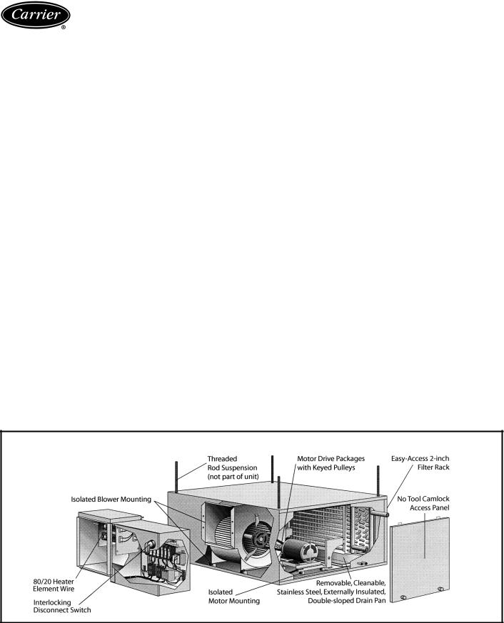
Fan wheels are designed to provide low operating costs
The forward-curved, centrifugal, double-inlet fans are statically and dynamically balanced at the factory to minimize transmission of vibration
to the building structure.
The belt-driven motor (single or three phase) has a variable-pitch pulley which adjusts at the jobsite to accommodate limited ranges of air quantities and pressures.
All motors (single and three phase) are UL listed, factory wired, single speed with thermal overload protection and are continuous duty rated. Motors are supplied with permanently lubricated bearings, class-B insulation and are open drip-proof. The motor mount has an adjustable platform for easy belt adjustment. The motor and its mounting are independently isolated from the cabinet and the blower. An adjustable pitch pulley allows cfm balancing to meet system requirements. Motor drive packages are provided with keyed pulleys.
Complete factory assembly minimizes on-the-jobsite costs and problems
Compact, lightweight units are designed for easy mounting. Knockouts designed to accept 3/8-in. threaded rods are
provided on the top and bottom of each corner of the unit One-in. duct collars on discharge and on return are furnished standard. These integral duct collars cut installation time and labor expense.
Durable construction means easy-to-maintain units
The 42BHC,BVC fan coils casings are fabricated from heavy-gage galvanized G90 steel, reinforced for maximum rigidity and structural strength. Removable side panels with tool-less camlock fasteners allow easy access for servicing interior components.
One-inch matte surface, fiberglass thermal/acoustical insulation lines the fan coil cabinets to prevent sweating and to muffle sound transmission.
The stainless steel, double-sloped condensate drain pan extends under full coil surface to cut maintenance costs.
Slide-in return-duct collar filter makes it possible to remove and replace the filter without disturbing return air ductwork.
Table of contents
Page
Features/Benefits. . . . . . . . . . . . . . . . . . . . . . . . . . . . . . . . . . . . . . . . . . . 1,2
Model Number Nomenclature . . . . . . . . . . . . . . . . . . . . . . . . . . . . . . . . . . . 3
Physical Data. . . . . . . . . . . . . . . . . . . . . . . . . . . . . . . . . . . . . . . . . . . . . . . 3
Options and Accessories. . . . . . . . . . . . . . . . . . . . . . . . . . . . . . . . . . . . . . 4,5
Base Unit Dimensions . . . . . . . . . . . . . . . . . . . . . . . . . . . . . . . . . . . . . . 6-13
Accessory Dimensions . . . . . . . . . . . . . . . . . . . . . . . . . . . . . . . . . . . . . 14-18
Application Data . . . . . . . . . . . . . . . . . . . . . . . . . . . . . . . . . . . . . . . . . 19-21
Selection Procedure . . . . . . . . . . . . . . . . . . . . . . . . . . . . . . . . . . . . . . . . . 22
Performance Data . . . . . . . . . . . . . . . . . . . . . . . . . . . . . . . . . . . . . . . 23-33
Typical Wiring Schematics . . . . . . . . . . . . . . . . . . . . . . . . . . . . . . . . . . 34-36
Electrical Data . . . . . . . . . . . . . . . . . . . . . . . . . . . . . . . . . . . . . . . . . . . . . 37
Controls . . . . . . . . . . . . . . . . . . . . . . . . . . . . . . . . . . . . . . . . . . . . . . . . . 38
Guide Specifications. . . . . . . . . . . . . . . . . . . . . . . . . . . . . . . . . . . . . . . 39,40
INTERNAL FEATURES OF A 42BHC FAN COIL UNIT
2
Model number nomenclature
42BH C 08 L
42BH — Vertical Belt Drive Fan Coil Unit
42BV — Vertical Belt Drive Fan Coil Unit
C — Design
Size — Nominal Cfm
06 — 600
08 — 800
10 — 1000
12 — 1200
16 — 1600
20 — 2000
30 — 3000
40 — 4000
NOTE: Refer to current 42 Series Master Prices for complete model definition, including motor, cfm and total static pressure.
Coil — Rows
B — 4, 2-Pipe
L — 6, 2-Pipe
H — 4/1, Same End Conn.
K — 4/2, Same End Conn.
N — 6/1, Same End Conn.
Q— 6/2, Same End Conn.
R— 8, 2-Pipe
1— 4 With Electric Heat
2— 6 With Electric Heat
3— 8 With Electric Heat
Physical data
UNIT SIZE 42BHC, BVC |
06 |
|
08 |
|
10 |
|
12 |
|
16 |
|
20 |
|
30 |
|
40 |
NOMINAL CFM |
600 |
|
800 |
|
1000 |
|
1200 |
|
1600 |
|
2000 |
|
3000 |
|
4000 |
42BHC SHIPPING WT (lb) |
203/234 |
|
205/236 |
|
253/287 |
|
256/290 |
|
312/346 |
|
344/380 |
|
437/474 |
|
553/590 |
(no heat/ with heat) |
|
|
|
|
|
|
|
||||||||
|
|
|
|
|
|
|
|
|
|
|
|
|
|
|
|
42BVC SHIPPING WT (lb) |
200/231 |
|
202/233 |
|
243/277 |
|
247/281 |
|
289/323 |
|
351/387 |
|
436/473 |
|
522/559 |
(no heat/ with heat) |
|
|
|
|
|
|
|
||||||||
|
|
|
|
|
|
|
|
|
|
|
|
|
|
|
|
FILTERS (2 in. pleated) |
|
|
|
|
|
|
|
|
|
|
|
|
|
|
|
Number...Size (in.) |
1...161/2 x 24 |
|
1...161/2 x 24 |
|
1...181/4 x 33 |
|
1...181/4 x 33 |
2...181/4 x 211/2 |
|
2...203/4 x 22 |
|
2...29 x 22 |
|
2...29 x 29 |
|
Face Area (sq ft) |
2.8 |
|
2.8 |
|
4.2 |
|
4.2 |
|
5.5 |
|
6.3 |
|
8.9 |
|
11.7 |
COILS |
|
|
|
|
|
|
|
|
|
|
|
|
|
|
|
Size (in.) |
15 x 20 |
|
15 x 20 |
|
15 x 29 |
|
15 x 29 |
|
15 x 39 |
|
18 x 40 |
|
27 x 40 |
|
27 x 54 |
Face Area (sq ft) |
2.1 |
|
2.1 |
|
3.0 |
|
3.0 |
|
4.1 |
|
4.9 |
|
7.7 |
|
10.3 |
Fins per inch |
|
|
|
|
|
10 |
|
|
|
|
|
|
|
||
Coil Water Weight (approx. lb per |
0.240 |
|
0.240 |
|
0.324 |
|
0.324 |
|
0.420 |
|
0.492 |
|
0.768 |
|
1.020 |
|
|
|
|
|
|
|
|||||||||
row of coil) |
|
|
|
|
|
|
|
||||||||
|
|
|
|
|
|
|
|
|
|
|
|
|
|
|
|
FANS |
|
|
|
|
|
|
|
|
|
|
|
|
|
|
|
Number...Size (in.) |
1...9 x 4 |
|
1...9 x 6 |
|
1...10 x 4 |
|
1...10 x 7 |
|
1...11 x 10 |
|
1...12 x 9 |
|
1...12 x 12 |
|
1...15 x 12 |
COPPER COIL CONN. 8 ROW |
|
|
|
|
1 OD |
|
|
|
|
11/2 OD |
|||||
(in.) (Cooling) |
|
|
|
|
|
|
|
|
|||||||
|
|
|
|
|
|
|
|
|
|
|
|
|
|
|
|
COPPER COIL CONN. 4 AND 6 ROW |
|
3/4 |
|
OD |
|
|
|
1 OD |
|
11/2 OD |
|||||
(in.) (Cooling) |
|
|
|
|
|
|
|||||||||
|
|
|
|
|
|
|
|
|
|
|
|
|
|
|
|
COPPER COIL CONN. 1 AND 2 ROW |
|
|
|
|
|
|
1/2 OD |
|
|
|
|
|
|
|
|
(in.) (Heating) |
|
|
|
|
|
|
|
|
|
|
|
|
|
||
|
|
|
|
|
|
|
|
|
|
|
|
|
|
|
|
DRAIN CONN. SIZES (in.) |
|
|
|
|
|
|
3/4 MPT |
|
|
|
|
|
|
|
|
3

Options and accessories
42BHC, BVC OPTIONS AND ACCESSORIES
ITEM |
OPTION* |
ACCESSORY† |
Automatic Air Vents |
X |
|
Controls |
X |
|
Electric Heat |
X |
|
Filters |
X |
|
Heating/Cooling Coils |
X |
|
Insulation |
X |
|
Mixing Boxes |
|
X |
Motors |
X |
|
Thermostats |
|
X |
Valve Packages |
|
X |
*Factory-installed option. |
|
|
†Field-installed accessory. |
|
|
The 42BHC and 42BVC fan coil units are designed to offer maximum flexibility in an application, accessibility for service, quiet operation and durability.
Factory-installed options
Automatic air vents — Automatic air vents have fiberwashers, which allow air in the pipes to pass through, automatically bleeding the system. The fiber washers eliminate the need to manually remove air from the system. When wet, washers swell and seal the system.
Coils — Coils are available in a choice of two-pipe system with 4-row cooling/heating or four-pipe system with 4, 6 or 8-row cooling and 1 or 2 row heating.
Reheat operation is standard. Preheat is available as an option.
Controls
•Interlocking disconnect switch
•Heater power fusing
•24 v Class 2 transformer (40 va)
•8-pole control terminal strip
•Auto reset temperature limit switch
•Airflow safety switch
•Motor power fusing
•Motor control contactor
•24 v condensate overflow switch
Electric heat — Total electric heat eliminates the requirement for a boiler. Heating and/or cooling may be available on an individual basis throughout the year. Resistance electric heat is available from 1.0 kW to 40.0 kW (refer to
electric heater data table for availability per unit) with single-stage or multiple-stage, single power source.
Voltages:
•115 v, 208 v, 230 v and 277 v single-phase 60 Hz
•208 v, 230 v and 480 v three-phase 60 Hz
Electric heat is available with the following staging options (3-phase staging is balanced).
•1 to 12 kW 1 stage only — single phase
•3 to 12 kW 1 or 2 stage only — single phase
•1 to 40 kW 1 stage only — 3 phase
•4 to 40 kW 1 or 2 stage only — 3 phase
•12 to 40 kW 1, 2, or 3 stage — 3 phase
Heater coils are constructed of high-grade resistance wire that is supported by ceramic insulators on plated steel brackets. These heat elements are suspended directly in front of the outlet after the blower and the coil. High limit thermal cutouts protect the heater in the event of air failure.
Filters — Two in. pleated filters are standard. One-in. pleated, two 1-in. throwaway, or 2-in. MERV (minimum efficiency reporting value) 11 filters with 2-in. pleated pre-filter are available. The 2-in. MERV 11 filters with 2-in. pleated pre-filter include a filter rack.
Insulation — Tuf-Skin™ II (1-in. thick) insulation is standard. Units are available with ¾-in. closed cell, 1-in. Tuf-Skin Rx™ edge sealed, or 1-in. foil-faced insulation.
Motors — A wide selection of standard motors provides efficient operation in ducted applications with excellent performance with up to 2 inches of total static pressure.
Available motor options:
•115 v, 208 v, 230 v and 277 v single-phase 60 Hz
•208 v, 230 v and 460 v three-phase 60 Hz
•Open drip-proof motors
•External junction box
Field-installed accessories
Mixing boxes — Mixing boxes can be used when outside air is required for ventilation. Preassembled at the factory and shipped separately with base rails for field installation, mixing boxes include a linkage kit consisting of two crank arms, 2 swivels and either a 25 in. long (for sizes 06-16) or a 84 in. long (for sizes 20-40) rod for field installation of an actuator.
4

Thermostats — Three thermostats are available for field installation:
Honeywell T834C manual changeover, single-stage heat thermostat features:
•off-cool-heat system switch
•on-auto fan mode switch
•single-stage electric heat
•outside air signal
Honeywell T8500 digital, automatic/manual changeover, 2-stage heat thermostat features:
•digital display of temperatures and all functions
•off-cool-heat-auto system mode buttons
•single speed fan operation
•on-auto fan mode button
•single or two stage electric heat signal
•outside air signal
•remote temperature sensor available
Sunne T170 single-stage heat, 2-pipe heat/cool auto changeover thermostat features:
•digital display of ambient temperature and operating mode
•single fan speed operation, power and operating mode buttons
•continuous fan operation, cycling water control valve
•4-pipe ACO/MCO (automatic changeover/manual changeover) with “on-auto” fan mode button
•one or 2 stage electric heat signal available
•purge cycle and temperature sensor for 2-pipe cold water/hot water systems
•programmable operating range, dead band, digital display, temperature set-back
THERMOSTAT FUNCTIONS
|
|
|
|
THERMOSTATS |
|
||
SYSTEM |
FUNCTION |
CHANGEOVER |
Honeywell |
Honeywell |
Sunne |
||
|
|
|
|
T834C |
T8500 |
T170 |
|
2 Pipe |
HW-Heat Only |
ACO |
— |
X |
X |
||
2 Pipe |
CW-Cool Only |
ACO |
— |
X |
X |
||
2 Pipe |
CW/HW |
MCO |
— |
— |
X |
||
Heat/Cool |
ACO |
— |
— |
X |
|||
|
|
||||||
|
|
CW/HW |
MCO |
— |
— |
X |
|
2 Pipe |
Heat/Cool with |
ACO |
— |
— |
X |
||
|
|
Aux. Electric Heat |
|||||
2 Pipe |
CW-Cooling with |
MCO |
X |
X |
X |
||
Total Electric Heat |
ACO |
— |
X |
X |
|||
|
|
||||||
4 Pipe |
CW/HW |
MCO |
X |
X |
X |
||
Heat/Cool |
ACO |
— |
X |
X |
|||
|
|
||||||
|
LEGEND |
|
|
|
|
||
ACO — Automatic Changeover |
|
|
|
||||
Aux |
— Auxiliary |
|
|
|
|
||
CW |
— Chilled Water |
|
|
|
|
||
HW — Hot Water
MCO — Manual Changeover
Valve packages — Valve packages are factory assembled for field installation. Motorized valves (24 v) can be operated with power on with spring return or power off/power on.
It is recommended that basic motor controls are ordered when valve packages are ordered.
5
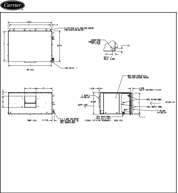
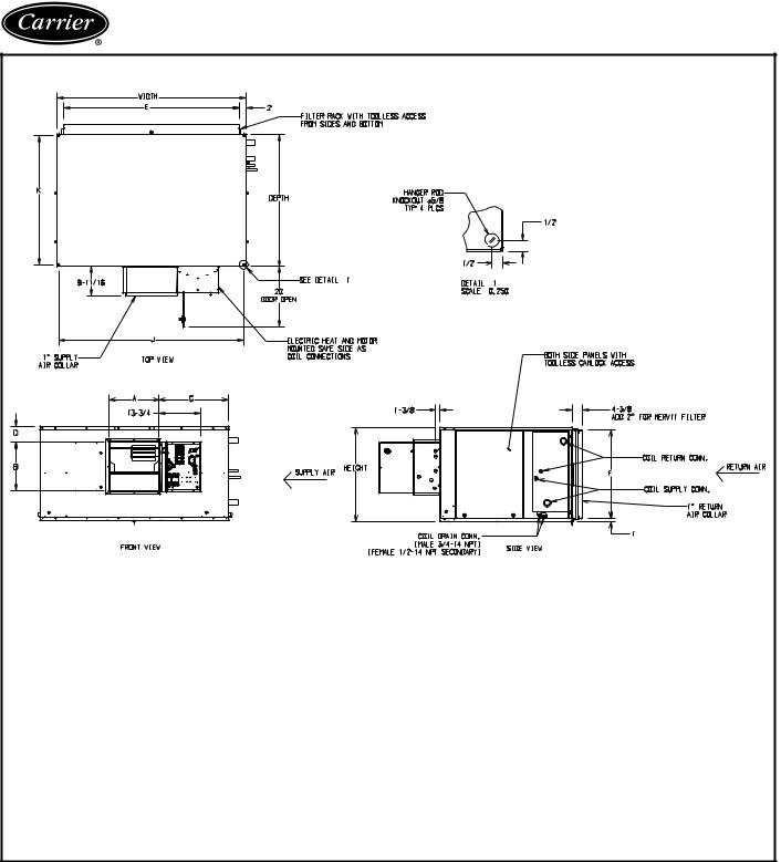
Base unit dimensions
42BHC FAN COIL BASE UNIT (NO CONTROLS)
UNIT |
|
|
|
|
|
|
DIMENSIONS (in.) |
|
|
|
|
|
|||
|
|
|
|
|
|
|
Supply Duct |
|
Return Duct |
Mounting Holes |
|||||
42BHC |
Fan Size |
Depth |
Width |
Height |
|
|
|||||||||
A |
B |
C |
D |
E |
F |
J |
K |
||||||||
|
|
|
|
|
|
|
|||||||||
06 |
|
9 x |
4 |
363/16 |
2811/16 |
181/2 |
71/8 |
109/16 |
137/8 |
11/8 |
241/16 |
167/16 |
273/16 |
351/4 |
|
08 |
|
9 x |
6 |
363/16 |
2811/16 |
181/2 |
89/16 |
109/16 |
137/8 |
11/8 |
241/16 |
167/16 |
273/16 |
351/4 |
|
10 |
|
10 x |
4 |
373/4 |
371/16 |
201/4 |
71/2 |
1111/16 |
137/8 |
11/8 |
331/16 |
183/16 |
363/16 |
3613/16 |
|
12 |
|
10 x |
7 |
373/4 |
371/16 |
201/4 |
915/16 |
1111/16 |
137/8 |
11/8 |
331/16 |
183/16 |
363/16 |
3613/16 |
|
16 |
|
11 x 10 |
3715/16 |
471/16 |
201/4 |
135/16 |
1211/16 |
1613/16 |
11/8 |
431/16 |
183/16 |
463/16 |
37 |
||
20 |
|
12 x |
9 |
403/8 |
481/16 |
223/4 |
121/2 |
133/4 |
173/4 |
11/8 |
441/16 |
2011/16 |
473/16 |
397/16 |
|
30 |
|
12 x 12 |
403/8 |
481/16 |
31 |
157/8 |
133/4 |
161/16 |
61/8 |
441/16 |
2815/16 |
473/16 |
397/16 |
||
40 |
|
15 x 12 |
439/16 |
621/16 |
31 |
167/16 |
161/16 |
2213/16 |
51/8 |
581/16 |
2815/16 |
613/16 |
425/8 |
||
NOTES:
1.All dimensions are in inches (±1/4 in.).
2.Any modifications to product specifications by any person are subject to acceptance of the factory. Product specifications are subject to change without notice.
3.Right hand shown, left hand opposite.
4.Hanger rods, which are field-supplied, are shown for reference only.
6
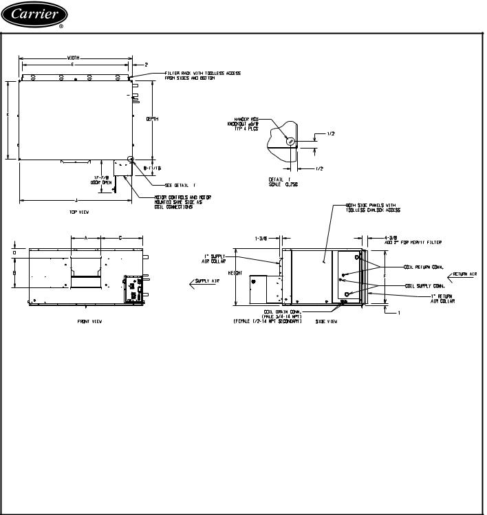
42BHC FAN COIL WITH MOTOR CONTROL OPTION
UNIT |
|
|
|
|
|
DIMENSIONS (in.) |
|
|
|
|
|
|||
|
|
|
|
|
|
Supply Duct |
|
Return Duct |
Mounting Holes |
|||||
42BHC |
Fan Size |
Depth |
Width |
Height |
|
|
||||||||
A |
B |
C |
D |
E |
F |
J |
K |
|||||||
|
|
|
|
|
|
|||||||||
06 |
9 x |
4 |
363/16 |
2811/16 |
181/2 |
71/8 |
109/16 |
137/8 |
11/8 |
241/16 |
167/16 |
273/16 |
351/4 |
|
08 |
9 x |
6 |
363/16 |
2811/16 |
181/2 |
89/16 |
109/16 |
137/8 |
11/8 |
241/16 |
167/16 |
273/16 |
351/4 |
|
10 |
10 x |
4 |
373/4 |
371/16 |
201/4 |
71/2 |
1111/16 |
137/8 |
11/8 |
331/16 |
183/16 |
363/16 |
3613/16 |
|
12 |
10 x |
7 |
373/4 |
371/16 |
201/4 |
915/16 |
1111/16 |
137/8 |
11/8 |
331/16 |
183/16 |
363/16 |
3613/16 |
|
16 |
11 x 10 |
3715/16 |
471/16 |
201/4 |
135/16 |
1211/16 |
1613/16 |
11/8 |
431/16 |
183/16 |
463/16 |
37 |
||
20 |
12 x |
9 |
403/8 |
481/16 |
223/4 |
121/2 |
133/4 |
173/4 |
11/8 |
441/16 |
2011/16 |
473/16 |
397/16 |
|
30 |
12 x 12 |
403/8 |
481/16 |
31 |
157/8 |
133/4 |
161/16 |
61/8 |
441/16 |
2815/16 |
473/16 |
397/16 |
||
40 |
15 x 12 |
439/16 |
621/16 |
31 |
167/16 |
161/16 |
2213/16 |
51/8 |
581/16 |
2815/16 |
613/16 |
425/8 |
||
NOTES:
1.All dimensions are in inches (±1/4 in.).
2.Any modifications to product specifications by any person are subject to acceptance of the factory. Product specifications are subject to change without notice.
3.Right hand shown, left hand opposite.
4.Hanger rods, which are field-supplied, are shown for reference only.
7
Base unit dimensions (cont)
42BHC FAN COIL WITH ELECTRIC HEAT OPTION
UNIT |
|
|
|
|
|
DIMENSIONS (in.) |
|
|
|
|
|
|||
|
|
|
|
|
|
Supply Duct |
|
Return Duct |
Mounting Holes |
|||||
42BHC |
Fan Size |
Depth |
Width |
Height |
|
|
||||||||
A |
B |
C |
D |
E |
F |
J |
K |
|||||||
|
|
|
|
|
|
|||||||||
06 |
9 x |
4 |
363/16 |
2811/16 |
181/2 |
71/8 |
109/16 |
137/8 |
11/8 |
241/16 |
167/16 |
273/16 |
351/4 |
|
08 |
9 x |
6 |
363/16 |
2811/16 |
181/2 |
89/16 |
109/16 |
137/8 |
11/8 |
241/16 |
167/16 |
273/16 |
351/4 |
|
10 |
10 x |
4 |
373/4 |
371/16 |
201/4 |
71/2 |
1111/16 |
137/8 |
11/8 |
331/16 |
183/16 |
363/16 |
3613/16 |
|
12 |
10 x |
7 |
373/4 |
371/16 |
201/4 |
915/16 |
1111/16 |
137/8 |
11/8 |
331/16 |
183/16 |
363/16 |
3613/16 |
|
16 |
11 x 10 |
3715/16 |
471/16 |
201/4 |
135/16 |
1211/16 |
1613/16 |
11/8 |
431/16 |
183/16 |
463/16 |
37 |
||
20 |
12 x |
9 |
403/8 |
481/16 |
223/4 |
121/2 |
133/4 |
173/4 |
11/8 |
441/16 |
2011/16 |
473/16 |
397/16 |
|
30 |
12 x 12 |
403/8 |
481/16 |
31 |
157/8 |
133/4 |
161/16 |
61/8 |
441/16 |
2815/16 |
473/16 |
397/16 |
||
40 |
15 x 12 |
439/16 |
621/16 |
31 |
167/16 |
161/16 |
2213/16 |
51/8 |
581/16 |
2815/16 |
613/16 |
425/8 |
||
NOTES:
1.All dimensions are in inches (±1/4 in.).
2.Any modifications to product specifications by any person are subject to acceptance of the factory. Product specifications are subject to change without notice.
3.Right hand shown, left hand opposite.
4.Hanger rods, which are field-supplied, are shown for reference only.
8
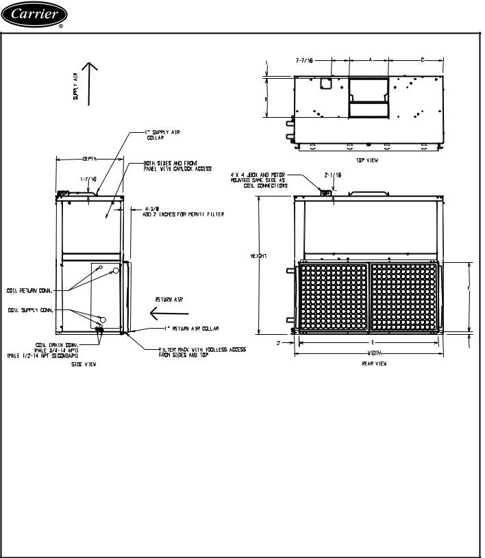
42BVC FAN COIL BASE UNIT (NO CONTROLS)
UNIT |
|
|
|
|
DIMENSIONS (in.) |
|
|
|
|
|
|
|
|
|
|
|
|
Supply Duct |
|
Return Duct |
|||
42BVC |
Fan Size |
Depth |
Width |
Height |
|
|
|||||
A |
B |
|
C |
E |
F |
||||||
|
|
|
|
|
|
|
|||||
06 |
9 x |
4 |
20 |
281/16 |
361/2 |
71/8 |
109/16 |
|
33/4 |
241/16 |
167/16 |
08 |
9 x |
6 |
20 |
281/16 |
361/2 |
89/16 |
109/16 |
|
33/4 |
241/16 |
167/16 |
10 |
10 x |
4 |
22 |
371/16 |
393/8 |
71/2 |
1111/16 |
|
51/2 |
331/16 |
183/16 |
12 |
10 x |
7 |
22 |
371/16 |
393/8 |
915/16 |
1111/16 |
|
51/2 |
331/16 |
183/16 |
16 |
11 x 10 |
22 |
471/16 |
393/8 |
135/16 |
1211/16 |
|
167/8 |
431/16 |
183/16 |
|
20 |
12 x |
9 |
24 |
481/16 |
451/8 |
121/2 |
133/4 |
|
1713/16 |
441/16 |
2011/16 |
30 |
12 x 12 |
28 |
481/16 |
543/16 |
157/8 |
133/4 |
|
161/8 |
441/16 |
2815/16 |
|
40 |
15 x 12 |
28 |
621/16 |
575/8 |
167/16 |
161/16 |
|
227/8 |
581/16 |
2815/16 |
|
NOTES:
1.All dimensions are in inches (±1/4 in.).
2.Any modifications to product specifications by any person are subject to acceptance of the factory. Product specifications are subject to change without notice.
3.Right hand shown, left hand opposite.
4.Hanger rods, which are field-supplied, are shown for reference only.
9
Base unit dimensions (cont)
42BVC FAN COIL WITH MOTOR CONTROL OPTION
|
|
|
|
|
|
|
|
|
|
|
|
|
|
|
|
|
|
|
|
|
|
|
|
|
|
|
|
|
|
|
|
|
|
|
|
|
|
|
UNIT |
|
|
|
|
|
|
DIMENSIONS (in.) |
|
|
|
|
|
|
|
|
|
|
|
|
|
|
|
|
|
|
Supply Duct |
|
Return Duct |
|
|||
|
|
|
42BVC |
Fan Size |
|
Depth |
Width |
|
Height |
|
|
||||||
|
|
|
|
|
A |
B |
|
C |
E |
F |
|
||||||
|
|
|
|
|
|
|
|
|
|
|
|
||||||
|
06 |
9 x |
4 |
|
20 |
281/16 |
|
361/2 |
71/8 |
109/16 |
|
33/4 |
241/16 |
167/16 |
|
||
|
08 |
9 x |
6 |
|
20 |
281/16 |
|
361/2 |
89/16 |
109/16 |
|
33/4 |
241/16 |
167/16 |
|
||
|
10 |
10 x |
4 |
|
22 |
371/16 |
|
393/8 |
71/2 |
1111/16 |
|
51/2 |
331/16 |
183/16 |
|
||
|
12 |
10 x |
7 |
|
22 |
371/16 |
|
393/8 |
915/16 |
1111/16 |
|
51/2 |
331/16 |
183/16 |
|
||
|
16 |
11 x 10 |
|
22 |
471/16 |
|
393/8 |
135/16 |
1211/16 |
|
167/8 |
431/16 |
183/16 |
|
|||
|
20 |
12 x |
9 |
|
24 |
481/16 |
|
451/8 |
121/2 |
133/4 |
|
1713/16 |
441/16 |
2011/16 |
|
||
|
30 |
12 x 12 |
|
28 |
481/16 |
|
543/16 |
157/8 |
133/4 |
|
161/8 |
441/16 |
2815/16 |
|
|||
40 |
15 x 12 |
|
28 |
621/16 |
|
575/8 |
167/16 |
161/16 |
|
227/8 |
581/16 |
2815/16 |
|
||||
|
|
|
NOTES: |
|
|
|
|
|
|
|
|
|
|
|
|
|
|
|
|
|
1. All dimensions are in inches (±1/4 in.). |
|
|
|
|
|
|
|
|
|
|
||||
|
|
|
2. Any modifications to product specifications by any person are subject to acceptance of the factory. Product specifications are subject to |
||||||||||||||
NOTES: |
|
|
|
|
|
|
|
|
|
|
|
|
|
|
|||
|
|
|
change without notice. |
|
|
|
|
|
|
|
|
|
|
|
|||
|
1. All dimensions are in inches (±1/4 in.). |
|
|
|
|
|
|
|
|
|
|
||||||
|
|
|
3. Right hand shown, left hand opposite. |
|
|
|
|
|
|
|
|
|
|
||||
|
2. Any modifications to product specifications by any person are |
|
|
|
|
|
|
|
|
||||||||
|
|
|
4. Hanger rods, which are field-supplied, are shown for reference only. |
|
|
|
|
|
|
|
|||||||
|
|
|
subject to acceptance of the factory. Product specifications are |
|
|
|
|
|
|
|
|
||||||
|
|
|
subject to change without notice. |
|
|
|
|
|
|
|
|
|
|
|
|||
3.RH shown, LH opposite.
4.Hanger rods, which are field-supplied, are shown for reference only.
10

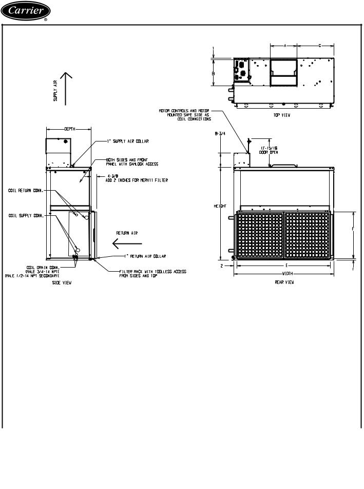
42BVC FAN COIL WITH ELECTRIC HEAT OPTION
UNIT |
|
|
|
|
DIMENSIONS (in.) |
|
|
|
|
||
|
|
|
|
|
|
Supply Duct |
|
Return Duct |
|||
42BVC |
Fan Size |
Depth |
Width |
Height |
|
|
|||||
A |
B |
C |
E |
F |
|||||||
|
|
|
|
|
|
||||||
06 |
9 x |
4 |
20 |
281/16 |
361/2 |
71/8 |
109/16 |
33/4 |
241/16 |
167/16 |
|
08 |
9 x |
6 |
20 |
281/16 |
361/2 |
89/16 |
109/16 |
33/4 |
241/16 |
167/16 |
|
10 |
10 x |
4 |
22 |
371/16 |
393/8 |
71/2 |
1111/16 |
51/2 |
331/16 |
183/16 |
|
12 |
10 x |
7 |
22 |
371/16 |
393/8 |
915/16 |
1111/16 |
51/2 |
331/16 |
183/16 |
|
16 |
11 x 10 |
22 |
471/16 |
393/8 |
135/16 |
1211/16 |
167/8 |
431/16 |
183/16 |
||
20 |
12 x |
9 |
24 |
481/16 |
451/8 |
121/2 |
133/4 |
1713/16 |
441/16 |
2011/16 |
|
30 |
12 x 12 |
28 |
481/16 |
543/16 |
157/8 |
133/4 |
161/8 |
441/16 |
2815/16 |
||
40 |
15 x 12 |
28 |
621/16 |
575/8 |
167/16 |
161/16 |
227/8 |
581/16 |
2815/16 |
||
NOTES:
1.All dimensions are in inches (±1/4 in.).
2.Any modifications to product specifications by any person are subject to acceptance of the factory. Product specifications are subject to change without notice.
3.Right hand shown, left hand opposite.
4.Hanger rods, which are field-supplied, are shown for reference only.
11
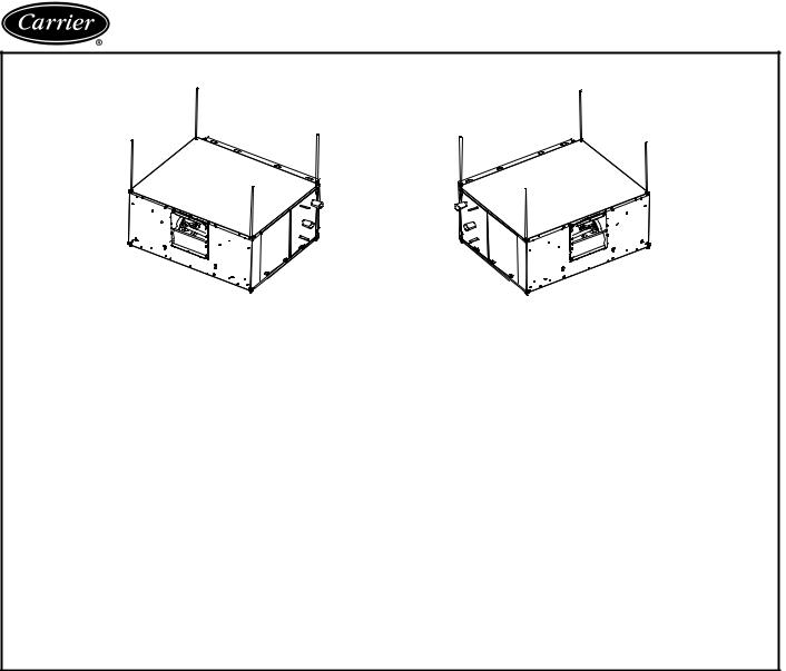
Base unit dimensions (cont)
42BHC UNIT CORNER WEIGHTS (lb)
1 |
|
2 |
|
|
|
2 |
1 |
4 |
3 |
|
|
|
|
4 |
3 |
|
|
RIGHT HAND UNIT |
|
|
|
|
LEFT HAND UNIT |
|||||
|
|
|
|
|
|
|
|
|
|
|
|
UNIT |
CONFIGURATION |
RIGHT-HAND UNITS |
LEFT-HAND UNITS |
TOTAL |
|||||||
42BHC |
1 |
2 |
3 |
4 |
1 |
2 |
3 |
4 |
WEIGHT |
||
|
|||||||||||
06 |
No Heat |
50 |
55 |
47 |
51 |
55 |
50 |
51 |
47 |
203 |
|
With Heat |
50 |
58 |
59 |
67 |
58 |
50 |
67 |
59 |
234 |
||
|
|||||||||||
08 |
No Heat |
51 |
55 |
47 |
52 |
55 |
51 |
52 |
47 |
205 |
|
With Heat |
50 |
59 |
59 |
68 |
59 |
50 |
68 |
59 |
236 |
||
|
|||||||||||
10 |
No Heat |
63 |
71 |
55 |
63 |
71 |
63 |
63 |
55 |
253 |
|
With Heat |
62 |
76 |
68 |
81 |
76 |
62 |
81 |
68 |
287 |
||
|
|||||||||||
12 |
No Heat |
64 |
72 |
56 |
64 |
72 |
64 |
64 |
56 |
256 |
|
With Heat |
63 |
76 |
68 |
82 |
76 |
63 |
82 |
68 |
290 |
||
|
|||||||||||
16 |
No Heat |
80 |
87 |
69 |
76 |
87 |
80 |
76 |
69 |
312 |
|
With Heat |
79 |
91 |
82 |
95 |
91 |
79 |
95 |
82 |
346 |
||
|
|||||||||||
20 |
No Heat |
90 |
98 |
74 |
82 |
98 |
90 |
82 |
74 |
344 |
|
With Heat |
90 |
102 |
88 |
100 |
102 |
90 |
100 |
88 |
380 |
||
|
|||||||||||
30 |
No Heat |
118 |
127 |
92 |
100 |
127 |
118 |
100 |
92 |
437 |
|
With Heat |
118 |
131 |
106 |
119 |
131 |
118 |
119 |
106 |
474 |
||
|
|||||||||||
40 |
No Heat |
155 |
162 |
114 |
122 |
162 |
155 |
122 |
114 |
553 |
|
With Heat |
155 |
166 |
129 |
140 |
166 |
155 |
140 |
129 |
590 |
||
|
|||||||||||
NOTE: Unit weights (shown in pounds) ±10%, are based on the 8-row coil and 1 Hp motor.
12
Loading...