


38APS025-065 38APD025-130 Long Line Check Valve Accessory 50/60 Hz
Installation Instructions
Part No.: 38AP-900---011, 38AP-900---012, 38AP-900---013
SAFETY CONSIDERATIONS
When installing this accessory, observe precautions in the literature and on any labels attached to the equipment, and all other safety precautions that may apply.
•Follow all safety codes.
•Wear safety glasses and work gloves.
•Use care in handling and installing this accessory.
 WARNING
To avoid the possibility of electrical shock, open and tag all disconnects before installing this equipment. Failure to do so could result in severe personal injury.
INTRODUCTION
An accessory long line check valve must be installed for:
1.Any 025-030 size dual circuit unit where the evaporator is located higher than the condensing unit and the linear line length exceeds 55 ft (16.8 m).
2.Any size dual or single circuit unit with linear line length of 100 ft (30.5 m) or more.
The kit consists of a liquid line check valve and a bypass check valve to prevent charge migration to compressor.
INSTALLATION
 CAUTION
For all units with liquid lines of 100 ft (30.5 m) or more or any 025-030 size dual circuit unit application where evaporator is located higher than the condensing unit and liquid lines exceed 55 feet (16.8 m), a long line check valve must be installed to prevent compressor failure. The long line check valve accessory must be mounted in the liquid line as close as possible to the condensing unit.
The long line check valve accessory must be mounted in the liquid line near the condensing unit. The valve is brazed into the liquid line. Fitting adapters may be required to connect the check valve to the liquid line. The valve may be mounted in any orientation, horizontally or vertically. See Fig. 1 for dimensions. Figure 2 shows the location of the check valves on a rooftop installation. Figure 3 shows the location of the check valves on a ground level installation.
ACCESSORY USAGE
UNIT |
CIRCUIT |
CHECK |
ACCESSORY USAGE (QUANTITY) — PART NO. 38AP-900--- |
|||
VALVE SIZE |
|
|
|
|||
SIZE |
TYPE |
011 |
012 |
013 |
||
(in. ODF) |
||||||
|
|
|
|
|
|
|
38APD/S025 |
Dual |
5/8 + 5/8 |
2 |
— |
— |
|
|
|
|
|
|
||
Single |
5/8 |
1 |
— |
— |
||
|
||||||
|
|
|
|
|
|
|
38APD/S027 |
Dual |
5/8 + 5/8 |
2 |
— |
— |
|
|
|
|
|
|
||
Single |
5/8 |
1 |
— |
— |
||
|
||||||
|
|
|
|
|
|
|
38APD/S030 |
Dual |
5/8 + 5/8 |
2 |
— |
— |
|
|
|
|
|
|
||
Single |
7/8 |
— |
1 |
— |
||
|
||||||
|
|
|
|
|
|
|
38APD/S040 |
Dual |
5/8 + 5/8 |
2 |
— |
— |
|
|
|
|
|
|
||
Single |
7/8 |
— |
1 |
— |
||
|
||||||
|
|
|
|
|
|
|
38APD/S050 |
Dual |
5/8 + 5/8 |
2 |
— |
— |
|
|
|
|
|
|
||
Single |
7/8 |
— |
1 |
— |
||
|
||||||
|
|
|
|
|
|
|
38APD060 |
Dual |
5/8 + 7/8 |
1 |
1 |
— |
|
|
|
|
|
|
|
|
38APS065 |
Single |
7/8 |
— |
1 |
— |
|
|
|
|
|
|
|
|
38APD070 |
Dual |
7/8 + 7/8 |
— |
2 |
— |
|
|
|
|
|
|
|
|
38APD080 |
Dual |
7/8 + 7/8 |
— |
2 |
— |
|
|
|
|
|
|
|
|
38APD090 |
Dual |
7/8 + 7/8 |
— |
2 |
— |
|
|
|
|
|
|
|
|
38APD100 |
Dual |
7/8 + 7/8 |
— |
2 |
— |
|
|
|
|
|
|
|
|
38APD115 |
Dual |
7/8 + 7/8 |
— |
2 |
— |
|
|
|
|
|
|
|
|
38APD130 |
Dual |
7/8 + 1 1/8 |
— |
1 |
1 |
|
|
|
|
|
|
|
|
Manufacturer reserves the right to discontinue, or change at any time, specifications or designs without notice and without incurring obligations.
Catalog No. 04-53380009-01 |
Printed in U.S.A. |
Form 38AP-5SI |
Pg 1 |
5-10 |
Replaces: New |
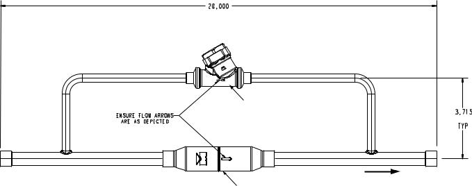
20.000
(508)
|
BYPASS CHECK VALVE |
|
ENSURE FLOW ARROWS |
3.715 |
|
(94) |
||
ARE AS DEPICTED |
||
TYP |
||
|
|
DIRECTION |
LIQUID LINE CHECK VALVE |
OF FLOW |
|
NOTE: Dimensions are in inches. Dimensions in () are in millimeters.
Fig. 1 — Long Line Check Valve Accessory Dimensions (Part No. 38AP-900---011 Shown)
2
 Loading...