


 Loading...
Full Auto Tonometer
Operation Manual
Make sure you read this manual before using the instrument. Keep this manual in a safe place so that you can use it in the future.
L-IE-5191C_TX-20.indb |
1 |
|
|
2013/07/18 |
13:10:07 |
|
|
||||
|
|
|
|
|
|
|
|
|
|
|
|

Thank you for purchasing the Canon Full Auto Tonometer TX-20 (referred to as “TX-20” in this manual). Be sure to read this manual thoroughly before using the instrument, and apply the information that you learn.
Important
•The TX-20 must only be used by a doctor or a legally qualified person.
•The user is responsible for managing the usage and maintenance of medical equipment. We suggest that a dedicated individual is assigned responsibility for maintenance to ensure that the TX-20 is kept in good condition and can be used safely.
•Rx Only (USA) Federal law restricts this device to sale by or on the order of a physician.
Disclaimers
•Canon takes no responsibility for damage that occurs due to fires, earthquakes, third-party actions, other accidents, the user's deliberate misuse, negligence, experimentation, or use under other abnormal conditions.
•Canon takes no responsibility for direct or consequential damages resulting from the use or the inability to use the TX-20.
•Canon takes no responsibility for injuries or property damage that may occur if safety precautions are not followed or the instrument is used for something other than its intended purpose.
•Medical examinations are the responsibility of a doctor. Canon takes no responsibility for diagnostic results.
•The information in this manual may be changed without prior notice.
•Although we have made every effort to ensure the accuracy of the information in this manual, if you have any questions regarding the contents, please contact your sales representative or local Canon dealer.
Installation
• Request your sales representative or local Canon dealer to install the TX-20.
Trademarks
•Canon and the Canon logo are trademarks of Canon Inc.
•Other system names and product names that appear in this manual are trademarks of their respective companies.
Copyright
•The copyright of this manual belongs to Canon Inc.
•Unauthorized reproduction, duplication, or reprinting of this manual in whole or in part is prohibited.
2
L-IE-5191C_TX-20.indb |
2 |
|
|
2013/07/18 |
13:10:07 |
|
|
||||
|
|
|
|
|
|
|
|
|
|
|
|

Contents |
|
1 Introduction................................................................................................. |
5 |
Features...................................................................................................... |
5 |
Indications for Use...................................................................................... |
5 |
Components............................................................................................... |
6 |
Conventions Used in This Manual.............................................................. |
7 |
2 Safety............................................................................................................ |
8 |
Regulatory Information............................................................................... |
8 |
Safety Precautions.................................................................................... |
10 |
Notes on Using TX-20............................................................................... |
14 |
Labels and Symbols................................................................................. |
17 |
3 Names of Parts.......................................................................................... |
19 |
Main Unit (From the Examiner's Side)...................................................... |
19 |
Main Unit (From the Patient's Side).......................................................... |
20 |
Bottom Side.............................................................................................. |
21 |
Operation Panel........................................................................................ |
22 |
Operation Lever........................................................................................ |
23 |
Monitor Panel............................................................................................ |
24 |
Measurement Screen................................................................................ |
25 |
PATIENT ID Screen................................................................................... |
27 |
DATA Screen............................................................................................. |
28 |
MENU Screen........................................................................................... |
29 |
Screen that Appears When Measurement Fails....................................... |
30 |
Anterior Segment Image Display Screen............................................... |
30 |
Anterior Segment Image and Intraocular Pressure Measurement |
|
Waveform Display Screen...................................................................... |
31 |
Other Screens........................................................................................... |
32 |
USB Connection Check Screen............................................................. |
32 |
Print Message Input Screen .................................................................. |
32 |
User Name Input Screen........................................................................ |
33 |
Password Input Screen ......................................................................... |
33 |
Computer Name Input Screen............................................................... |
34 |
Output Folder Name Input Screen ........................................................ |
34 |
LCD Brightness Adjustment Screen ..................................................... |
35 |
Description of Printouts ........................................................................... |
36 |
4 Basic Operation......................................................................................... |
37 |
Flow of Operations.................................................................................... |
37 |
Connecting Cables .................................................................................. |
38 |
Preparations Prior to an Examination....................................................... |
40 |
Patient Setup............................................................................................. |
41 |
Measuring................................................................................................. |
43 |
Finishing an Examination.......................................................................... |
47 |
Power Saving Mode.................................................................................. |
48 |
Recovering from the Power Saving Mode.............................................. |
48 |
5 Types of Measurements........................................................................... |
49 |
Measurement Screen................................................................................ |
49 |
Changing the Alignment Mode .............................................................. |
49 |
Changing the Number of Measurements .............................................. |
50 |
Changing the Eye Fixation Lamp .......................................................... |
51 |
PATIENT ID Screen .................................................................................. |
51 |
Input Patient ID in the PATIENT ID Screen............................................. |
52 |
Input Patient ID from an External Device .............................................. |
56 |
MENU Screen .......................................................................................... |
57 |
MENU Screen Display and Functions of Buttons ................................. |
57 |
3
L-IE-5191C_TX-20.indb |
3 |
|
|
2013/07/18 |
13:10:07 |
|
|
||||
|
|
|
|
|
|
|
|
|
|
|
|

Basic Operations on MENU Screen ...................................................... |
58 |
Common Settings in Measurement Modes .......................................... |
61 |
Settings for Intraocular Pressure Measurements ................................. |
62 |
Settings for Printing ............................................................................... |
63 |
Settings for Patient ID Input Interface ................................................... |
64 |
Settings for Interface of Output of Measurements ............................... |
64 |
Settings for Patient No. ......................................................................... |
67 |
Settings for Patient ID ............................................................................ |
68 |
Setting the Time, Date, and Power Saving Mode.................................. |
69 |
Settings for the LCD .............................................................................. |
69 |
Checking Firmware ................................................................................ |
70 |
6 Maintenance.............................................................................................. |
71 |
Daily Inspections ...................................................................................... |
71 |
Cleaning and Disinfection......................................................................... |
72 |
Refilling Chin Rest Paper.......................................................................... |
74 |
Replacing Printing Paper.......................................................................... |
74 |
Preparations for Packing and Transport ................................................. |
76 |
7 Troubleshooting........................................................................................ |
77 |
Symptom and Remedy............................................................................. |
77 |
Message and Remedy.............................................................................. |
78 |
Appendix........................................................................................................ |
87 |
Specifications........................................................................................... |
87 |
Stylesheet File........................................................................................... |
88 |
EMC (Electromagnetic Compatibility)....................................................... |
90 |
Warranty and Repair Service.................................................................... |
95 |
4
L-IE-5191C_TX-20.indb |
4 |
|
|
2013/07/18 |
13:10:08 |
|
|
||||
|
|
|
|
|
|
|
|
|
|
|
|

1Introduction
Features
The Canon Full Auto Tonometer TX-20 has full auto-alignment for intraocular pressure measurement. The features of these products are shown below.
Three alignment modes
•In full auto mode, both eyes are measured and the results are printed automatically, shortening the time used for measuring.
•In auto mode, auto-alignment and measurement are performed each time the measurement button is pressed. The examiner can monitor the condition of the patient’s eyes while measuring them.
•In manual mode, measurements can be performed manually such as when the patient’s pupil is eccentric or cornea is deformed.
Compact, with superior operability
More compact and more lightweight than the previous model. Upright operations, patient care, alignment operation have been greatly improved with a tiltable color LCD monitor and powered operation lever.
Enhanced external interface
Measurement data can be exported via RS-232C connections or to a LAN. Patient ID can be input from a USB device.
Indications for Use
For USA
The Canon Full Auto Tonometer TX-20 is intended to be used for the measurement of intraocular pressure of the human eye.
For European Union
The TX-20 measures the intraocular pressure detecting the change of the cornea surface and the result will be provided for diagnosis.
5
L-IE-5191C_TX-20.indb |
5 |
|
|
2013/07/18 |
13:10:08 |
|
|
||||
|
|
|
|
|
|
|
|
|
|
|
|
1 Introduction
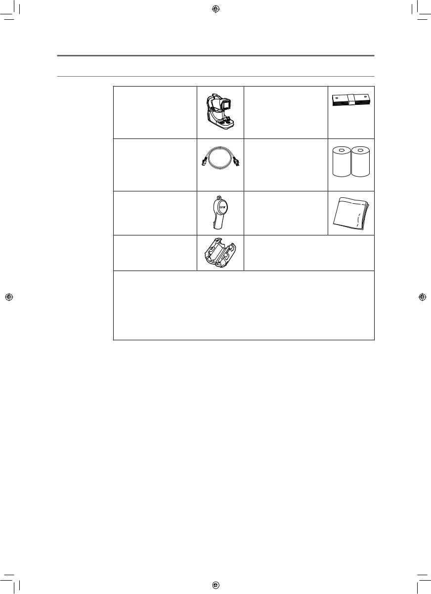
Components
Full Auto Tonometer TX-20 |
Chin rest paper |
Main unit |
100 sheets provided. |
Power cord |
Printing paper |
Connects the TX-20 to an AC |
2 rolls provided. |
outlet (3m). |
|
USA and Canada only: |
|
Plug type: VM0275 Hospital- |
|
Grade |
|
Nozzle cap |
Dust cover |
Initially covers the nozzle. |
Use it to cover the TX-20 when |
|
the instrument is not being |
|
used. |
Ferrite core |
|
If a LAN cable is being used, |
|
attach the ferrite core to it. |
|
Operation manual for the TX-20—this document
Describes the handling precautions and operating instructions for the TX-20.
Warranty Card (for USA model only)
WEEE Directive Leaflet (for EU model only)
Installation Report
Optional products
Chin rest paper—500 sheets
Printing paper—10 rolls
6
L-IE-5191C_TX-20.indb |
6 |
|
|
2013/07/18 |
13:10:09 |
|
|
||||
|
|
|
|
|
|
|
|
|
|
|
|
1 Introduction
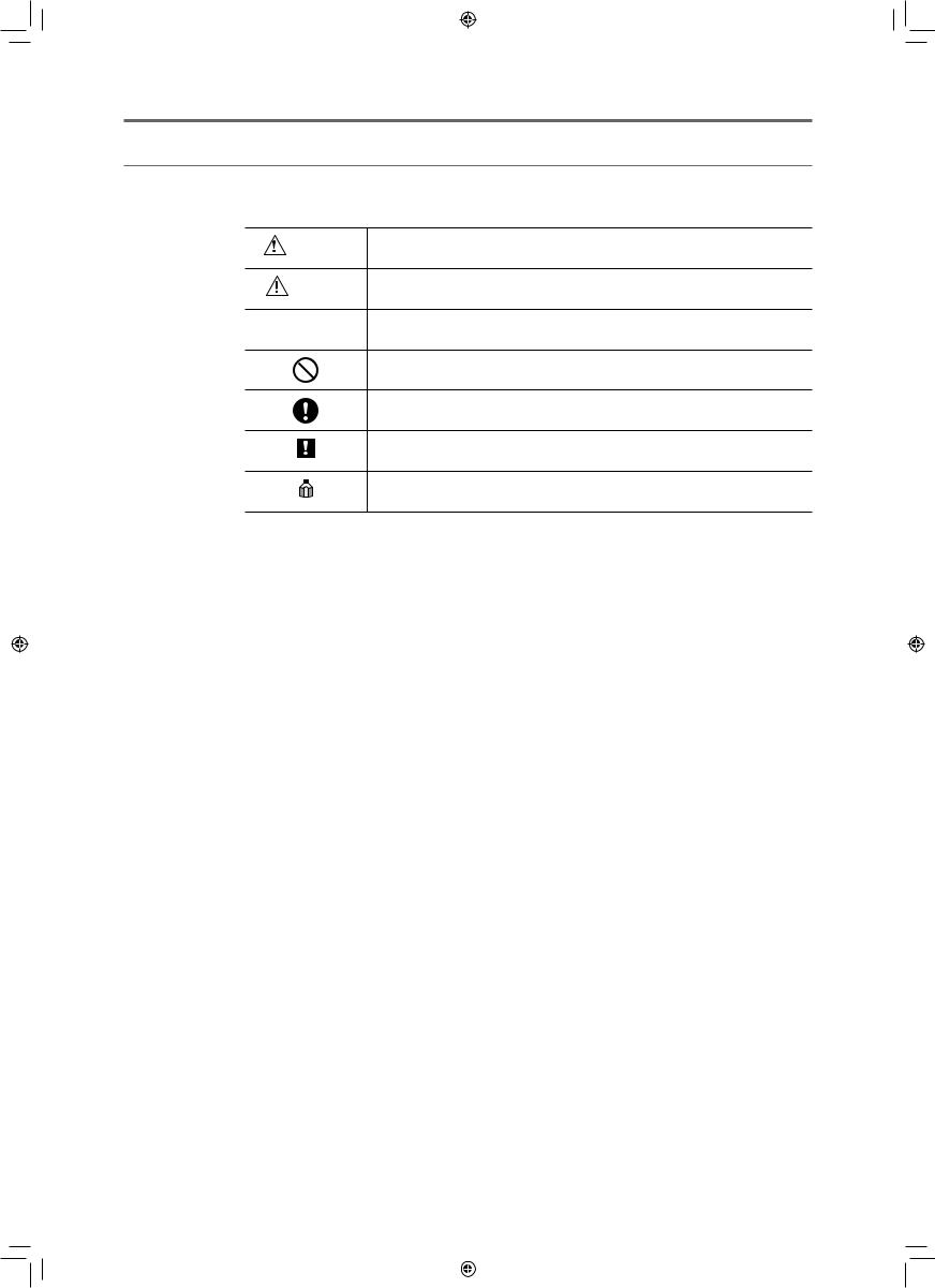
Conventions Used in This Manual
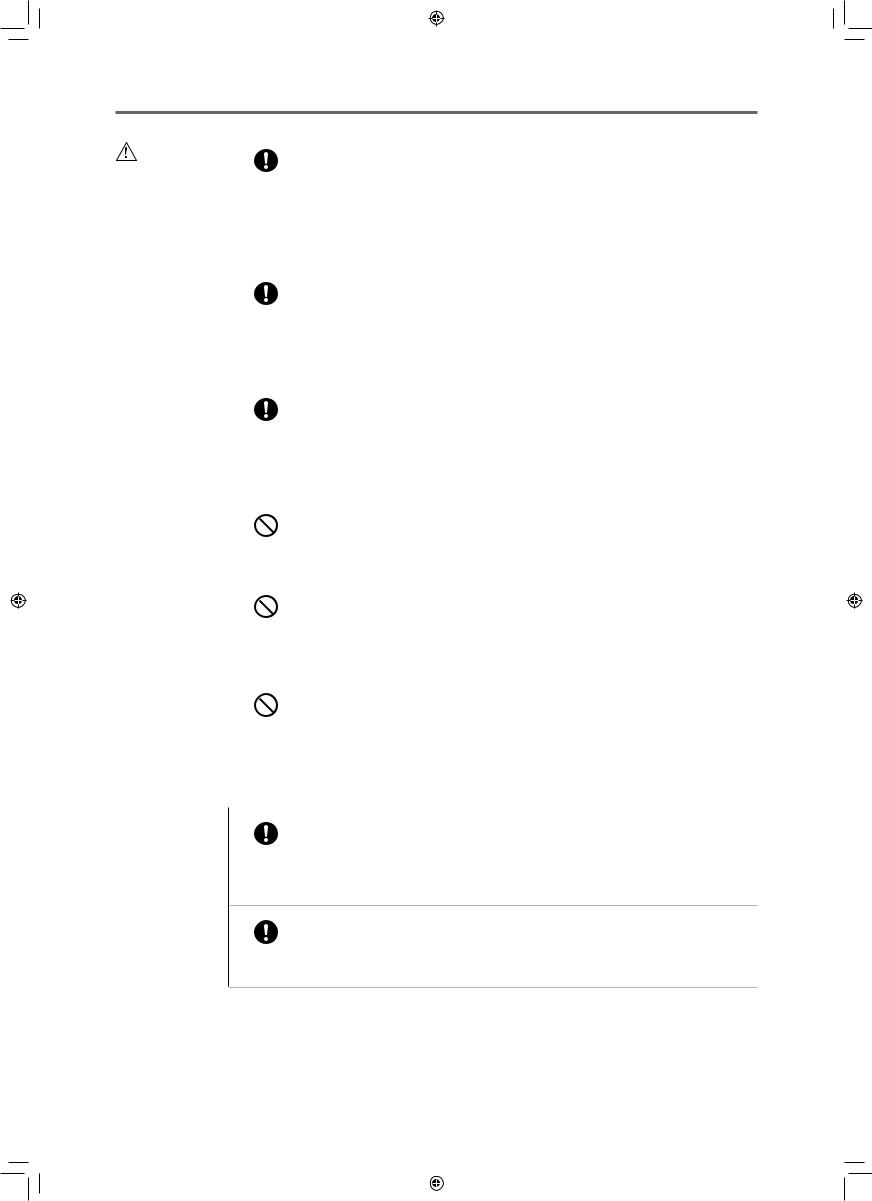
This manual uses the following symbols to indicate precautions that are important for using the TX-20 safely. Always follow these safety precautions.
WARNING |
A warning that incorrect operation may result in death or serious injury. |
|
|
||
CAUTION |
A caution that incorrect operation may result in serious injury. |
|
|
||
CAUTION |
A caution that incorrect operation may break the TX-20 or damage other |
|
devices. |
||
|
This symbol indicates actions that must not be taken (prohibited actions).
This symbol indicates actions that must be taken.
This symbol indicates important advice that we strongly recommend be followed while operating the TX-20.
This symbol indicates supplementary explanations or advice for operating the
TX-20.
References
This manual uses the following style to indicate reference destination.
Example: (see page 15)
7
L-IE-5191C_TX-20.indb |
7 |
|
|
2013/07/18 |
13:10:09 |
|
|
||||
|
|
|
|
|
|
|
|
|
|
|
|

2Safety
Regulatory Information
The following sections list the classifications applicable to the TX-20 and the directives and standards that the TX-20 complies with.
Device Classification
Type of protection against electric shock |
Class I equipment |
Degree of protection against electric shock |
Type B applied parts |
|
(Chin rest, forehead rest) |
Degree of protection against ingress of water |
IPX0 |
Degree of safety of application in the presence of a |
Not suitable |
flammable anaesthetic mixture with air or with oxygen or |
|
nitrous oxide |
|
Mode of operation |
Continuous operation |
Directives and Standards
USA and Canada
UL 60601-1:2003 |
Medical electrical equipment – Part 1: General requirements |
CAN/CSA C22.2 No.601.1-M90 |
for safety |
IEC 60601-1: 1988/A1: 1991/A2: 1995 |
|
IEC 60601-1:2005 |
Medical electrical equipment - Part1: General requirements |
|
for basic safety and essential performance |
IEC 60601-1-1: 2000 |
Medical electrical equipment – Part 1-1: General |
|
requirements for safety – Collateral standard: Safety |
|
requirements for medical electrical systems |
IEC 60601-1-2: 2001/A1:2004 |
Medical electrical equipment – Part 1-2: Collateral standard: |
IEC 60601-1-2:2007 |
Electromagnetic compatibility – Requirements and tests |
IEC 60601-1-4: 1996/A1: 1999 |
Medical electrical equipment – Part 1-4: Collateral standard: |
|
Programmable electrical medical systems |
IEC 62304: 2006 |
Medical device software – Software life-cycle processes |
IEC 62366: 2007 |
Medical device – Application of usability engineering to |
|
medical devices |
ISO 15004-1: 2006 |
Ophthalmic instruments – Part 1: General requirements |
|
applicable to all ophthalmic instruments |
ISO 15004-2: 2007 |
Ophthalmic instruments – Part 2: Light hazard protection |
8
L-IE-5191C_TX-20.indb |
8 |
|
|
2013/07/18 |
13:10:10 |
|
|
||||
|
|
|
|
|
|
|
|
|
|
|
|

|
2 Safety |
|
|
ISO 10993-1: 2009 |
Biological evaluation of medical devices – Evaluation and |
ISO 10993-5: 2009 |
testing |
ISO 10993-10: 2010 |
|
ISO 8612: 2001 |
Ophthalmic instruments – Tonometers |
ANSI Z80.10-2003 |
|
European Union |
|
93/42/EEC |
Medical Device Directive |
EN 60601-1:2006 |
Medical electrical equipment - Part1:General requirements |
|
for basic safety and essential performance |
EN 60601-1-2: 2007 |
Medical electrical equipment – Part 1-2: Collateral standard: |
|
Electromagnetic compatibility – Requirements and tests |
EN 60601-1-6: 2010 |
Medical electrical equipment – Part 1-6: Collateral standard: |
|
Usability |
EN 62304: 2006 |
Medical device software – Software life-cycle processes |
EN 62366: 2008 |
Medical device – Application of usability engineering to |
|
medical devices |
EN ISO 14971: 2009 |
Medical device – Application of risk management to |
|
medical devices |
EN ISO 15004-1: 2009 |
Ophthalmic instruments – Part 1: General requirements |
|
applicable to all ophthalmic instruments |
ISO 15004-2: 2007 |
Ophthalmic instruments – Part 2: Light hazard protection |
EN ISO 10993-1: 2009 |
Biological evaluation of medical devices |
EN ISO 10993-5: 2009 |
|
EN ISO 10993-10: 2010 |
|
ISO 8612: 2001 |
Ophthalmic instruments – Tonometers |
9
L-IE-5191C_TX-20.indb |
9 |
|
|
2013/07/18 |
13:10:10 |
|
|
||||
|
|
|
|
|
|
|
|
|
|
|
|
2 Safety
Safety Precautions
To prevent injuries and data loss, operate the TX-20 correctly by following the safety precautions.
WARNING |
|
To avoid the risk of electric shock, this instrument must only |
|
be connected into a supply mains with protective earth. |
|
|
|
|
|
|
|
|
|
Do not damage the power cord. |
|
Prohibited |
• Do not place anything heavy onto the power cord. |
|
• Do not damage or modify the power cord. |
|
|
|
|
|
|
• Do not forcibly bend, twist or pull the power cord. |
|
|
• Do not hold the power cord when removing it from the AC outlet. Be sure to hold |
|
|
the plug. |
|
|
Handle the power cord carefully. If the cord is damaged, contact your sales |
|
|
representative or local Canon dealer for a replacement. A damaged cord may result |
|
|
in fire or electric shock. |
|
|
|
|
|
Do not use a multiple power strip and an extension cable. |
|
Prohibited |
Connect the power cord directly to the AC outlet. Do not use a multiple power strip |
|
and an extension cable with it. |
|
|
|
|
|
|
|
|
|
Do not disassemble or modify. |
|
Prohibited |
A disassembled or modified instrument may result in fire or electric shock. Because |
|
the TX-20 incorporates high-voltage parts that may cause electric shocks, touching |
|
|
|
|
|
|
them may cause death or serious injury. |
|
|
|
|
|
Do not leave alcohol, thinner, or any flammable chemicals |
|
|
near the instrument. |
|
Prohibited |
Do not place near to a flammable solvent. Fire may result if the solvent spills or |
|
|
|
|
|
evaporates and makes contact with the internal electric parts. Some disinfectants |
|
|
are flammable. Be sure to take precautions when using them. |
|
|
|
|
|
Stop using immediately if there is an abnormality or problem. |
|
|
If an abnormality occurs, immediately unplug the power plug |
|
|
and turn off the power of all the devices. |
|
|
• Smoke is emitted |
|
|
• An unusual smell |
|
|
• An unusual noise |
|
|
• Foreign matter gets inside |
|
|
• Damaged |
|
|
Fire or electric shock may result if you continue use in such conditions. Immediately |
|
|
turn off the power of TX-20, unplug the power plug and turn off the power of all |
|
|
connected devices. Then, contact your sales representative or local Canon dealer. |
|
|
|
|
|
Do not place anything on top of the device. |
|
Prohibited |
Fire or electric shock may result if water or any other liquid or a needle, paper clip or |
|
any foreign matter gets inside the TX-20. |
|
|
|
|
|
|
|
10
L-IE-5191C_TX-20.indb |
10 |
|
|
2013/07/18 |
13:10:10 |
|
|
||||
|
|
|
|
|
|
|
|
|
|
|
|
2 Safety
WARNING |
|
Do not use a power supply voltage other than the one |
|
specified on the rating label. |
|
|
|
|
|
Prohibited |
Do not use any power cord other than the one supplied. |
|
|
Use the power voltage specified on the rating label. Otherwise, fire or electric shock may result.
The supplied power cord is designed exclusively for this product. Do not use any other power cord.
Do not plug or unplug the power plug with wet hands.
Do not plug or unplug the power plug or handle any other parts with wet hands.
Prohibited |
Otherwise, fire or electric shock may result. |
|
Unplug the plug periodically and remove any dust or dirt around the plug and the AC outlet.
If the cord is kept plugged in for a long time in a dusty, humid or sooty environment, dust around the plug will attract moisture, resulting in possible insulation failure that may result in a fire.
Insert the power plug completely.
Insert the power plug completely into the AC outlet. If a pin of the power plug makes contact with metal or any conductive object, fire or electric shock may result.
Do not clean the TX-20 with flammable solvent.
 For safety reasons, before cleaning the TX-20, be sure to turn off the power of all Prohibited the devices and unplug the power cord from the AC outlet. Do not use alcohol that
is not for cleaning, benzene, thinner or any other flammable solvent. Otherwise, fire or electric shock may result.
Turn off the power before inspection.
For safety reasons, before inspecting the instrument or cables, be sure to turn off the power of all the devices.
Otherwise, electric shock may result.
|
|
Do not measure an eye whose cornea is frail due to corneal |
|
|
disease or surgery. |
|
Prohibited |
Otherwise, complications may occur. |
|
|
|
|
|
|
|
|
Be sure to turn off the power before moving the TX-20. |
|
|
When moving the TX-20, always move the measurement unit to the packing position |
|
|
(see page 76), turn off the power, unplug the power cord, and disconnect any external |
|
|
equipment. Otherwise, the cable may be damaged, which may result in fire or |
|
|
electric shock. |
|
|
|
|
|
Use the indentations for lifting and moving the TX-20. |
|
|
When lifting the TX-20, hold it on the bottom and keep it level. Do not hold it by the |
|
|
head rest, nozzle or LCD monitor, as they may come off and result in injury. |
|
|
|
|
|
Do not touch conductive parts of non-medical equipment and |
|
|
the patient simultaneously. |
|
Prohibited |
Otherwise, electric shock may result. |
|
|
|
|
|
|
CAUTION |
|
Do not install in locations exposed to water, steam, moisture |
|
||
|
or dust. |
|
|
|
|
|
Prohibited |
Doing so may cause problems or malfunctions. |
|
|
|
|
|
|
11
L-IE-5191C_TX-20.indb |
11 |
|
|
2013/07/18 |
13:10:11 |
|
|
||||
|
|
|
|
|
|
|
|
|
|
|
|
2 Safety
CAUTION |
|
Do not install in locations exposed to salt, sulfur or corrosive |
|
gas. |
|
|
|
|
|
Prohibited |
Doing so may result in corrosion of the instrument, problems or malfunctions. |
|
|
|
|
|
|
|
|
Do not install in locations that are unstable or exposed to |
|
|
vibration. |
|
Prohibited |
The vibration may knock over the instrument or the instrument may become |
|
|
|
|
|
unbalanced and fall, resulting in a malfunction or injury. |
|
|
|
|
|
Do not place anything near the power plug. |
|
Prohibited |
To make it easy to unplug the power plug at any time, avoid putting any obstructions |
|
near the AC outlet. |
|
|
|
|
|
|
Fire or electric shock may result if the power plug is not unplugged during an |
|
|
emergency. |
|
|
|
|
|
Do not block the vent holes. |
|
Prohibited |
Doing so may cause the internal temperature to rise and result in fire. |
|
|
|
|
|
|
|
|
Do not put your hands or fingers near the measurement unit. |
|
Prohibited |
Your hand or fingers may be pinched and injured. |
|
Similarly, instruct the patient not to place his/her hands or fingers on the base. |
|
|
|
|
|
|
|
|
|
Hold the TX-20 when connecting or disconnecting a cable. |
|
|
For safety reasons, when connecting or disconnecting the power cord or any |
|
|
cable be sure to hold the main unit. Otherwise, the main unit may fall over, possibly |
|
|
causing injury. |
|
|
|
|
|
Ensure that the entire system conforms to IEC 60601-1-1. |
|
|
Use the computer and other equipment that conform to the system standard IEC |
|
|
60601-1 or IEC 60950-1 for the Full Auto Tonometer TX-20. Be sure that the entire |
|
|
system conforms to IEC 60601-1-1. Be sure to also use an isolation transformer |
|
|
conforming to IEC 60601-1 when a computer conforming to IEC 60950-1 is used. |
|
|
Otherwise, electric shock may occur. Ask your sales representative or local Canon |
|
|
dealer to connect it to a computer. |
|
|
|
|
|
Use an isolation transformer for LAN connections. |
|
|
If the LAN connector is being used to connect to a network, connect an isolation |
|
|
transformer for networks between the TX-20 and network devices (HUB etc.) and |
|
|
between network devices. |
|
|
If this is not done, there is a risk of short circuits or malfunctioning devices. Ask your |
|
|
sales representative or local Canon dealer to connect it to a network. |
|
|
|
|
|
Turn off the power and unplug the power cord before |
|
|
connecting cables. |
|
|
Always turn off the power and unplug the power cord before connecting the cables |
|
|
of any external devices to the TX-20. |
|
|
If this is not done, there is a risk of damage. |
|
|
|
|
|
Always disinfect the nozzle after measuring an infected |
|
|
patient’s eyes. |
|
|
A patient’s tears may get on the nozzle and cause a secondary infection. Always use |
|
|
a cotton swab or other appropriate material that has been treated with disinfectant |
|
|
ethanol to wipe the nozzle. |
|
|
|
12
L-IE-5191C_TX-20.indb |
12 |
|
|
2013/07/18 |
13:10:12 |
|
|
||||
|
|
|
|
|
|
|
|
|
|
|
|
2 Safety
CAUTION |
|
Keep the forehead rest and chin rest clean. |
|
To prevent the risk of infection, wipe the forehead rest with disinfectant ethanol for |
|
|
|
|
|
|
each patient. To ensure cleanliness, replace the chin rest paper for each patient. |
|
|
If the chin rest paper is not being used, be sure to disinfect the chin rest for each |
|
|
patient. |
|
|
For details on how to disinfect, consult a specialist. The forehead rest may be |
|
|
corroded if a disinfectant other than those above is used. |
|
|
|
|
|
Be sure to turn off the power when not in use. |
|
|
For safety reasons, be sure to turn off the power of all the devices when the TX-20 |
|
|
is not being used. |
|
|
Also, remove the power plug from the AC outlet and put on the cover when the TX- |
|
|
20 is not going to be used for a long time. |
|
|
Otherwise, dust or any foreign matter may accumulate and result in fire. |
|
|
|
|
|
Make sure to select the position where the nozzle stops for |
|
|
each patient. |
|
|
Look from the side of the patient when setting the stop position to see that the |
|
|
patient’s forehead and chin are firmly against the forehead rest and chin rest. If the |
|
|
stop position is not set correctly, the nozzle may contact the patient’s eye and result |
|
|
in injury. |
|
|
|
|
|
Do not touch the cutter for the printer. |
|
Prohibited |
Do not touch the cutter for the printer. Similarly, instruct the patient not to touch the |
|
cutter for the printer. |
|
|
|
|
|
|
Otherwise, it may result in injury. |
|
|
|
|
|
Do not touch the area around the printer or open the paper |
|
|
cover during or immediately after printing. |
|
Prohibited |
The printer’s thermal head and the surrounding area are very hot during and |
|
|
|
|
|
immediately after printing. To prevent burns, wait for the printer to cool before |
|
|
opening the paper cover to replace paper. |
|
|
|
|
|
Do not touch the measurement unit and the chin rest while |
|
|
they are moving. |
|
Prohibited |
The measurement unit and the chin rest move when the power is turned on, full |
|
|
|
|
|
auto is set, or the CHIN REST button is pressed. Do not touch the measurement |
|
|
unit or the chin rest while they are moving. Keep the patient’s chin away from the |
|
|
chin rest. |
|
|
|
CAUTION |
Use the product’s packaging to transport it. |
|
Use the TX-20 packing materials to protect it from vibration and shocks when it is |
|
transported on a cart, in a vehicle, or if shipped over long distances. |
|
Vibration or shock may cause a breakdown or damage the TX-20. |
|
For details, contact your sales representative or local Canon dealer. |
Inspect daily and periodically.
For safety reasons, before using the TX-20, be sure to perform the daily inspection.
Have a periodically inspection performed for the TX-20 at least once a year by a
Canon designated representative to maintain its performance and reliability.
13
L-IE-5191C_TX-20.indb |
13 |
|
|
2013/07/18 |
13:10:13 |
|
|
||||
|
|
|
|
|
|
|
|
|
|
|
|

2 Safety
Notes on Using TX-20
Before Use
•Sudden heating of the room in cold areas will cause condensation to form on the optical component of the nozzle and on optical parts inside the instrument. In this case, wait until condensation disappears before performing a measurement.
During Measurement
•Describe to the patient what to expect during measurement so he/she will not be surprised by the sudden air puff. Demonstrate the intensity of the air puff by having the patient place a finger in front of the nozzle and then press the CHECK button.
•The measurement unit automatically moves after the power is turned on. Do not prevent movement of the measurement unit by holding it or placing something near it.
Do not let the patient place his/her chin on the chin rest until the measurement unit stops.
•It is recommended that a hard copy of the printout be made if you wish to store it for a long time, because printouts on thermal paper are apt to deteriorate.
After Use
•Turn off the power, put the cap over the optical component of the nozzle in order to prevent dust from attaching to it, and place the dust cover over the instrument.
During Cleaning and Disinfection
•If the surface of the optical component of the nozzle is wiped when dust or dirt is on it, it will be scratched. Also, do not wipe the optical component with alcohol, including disinfectant ethanol or silicone-coated paper. Otherwise, the surface will be corroded or stained.
•Use neutral detergent for cleaning the outside of the TX-20. Do not use neutral detergent for cleaning the LCD monitor. See below for LCD cleaning instructions.
LCD Monitor
•Approximately 99.99% of the dots in high-technology LCD monitors are functional. About 0.01% of the dots may be missing or might appear as a bright spot. This is not a malfunction.
•The polarization plate on the surface of the monitor is very fragile. Be careful when handling it and do not press or rub any hard objects against it.
•Wipe water or saliva from the polarization plate on the monitor’s surface immediately; leaving it for a long time may cause distortion or discoloration.
•If the surface is dirty, use something soft, such as an absorbent cotton cloth, with a small amount of ethanol, and lightly wipe it.
14
L-IE-5191C_TX-20.indb |
14 |
|
|
2013/07/18 |
13:10:13 |
|
|
||||
|
|
|
|
|
|
|
|
|
|
|
|

2 Safety
Environment of Use
•Use, store, and transport the TX-20 in an environment that is within the range of the following conditions. Use the original packaging to store or ship it.
|
Temperature |
Humidity |
Atmospheric pressure |
|
|
|
|
Environment of use |
10 to 40°C |
30 to 90% RH (no |
600 to 1060 hPa |
|
|
condensation) |
|
Storage and transportation |
–30 to 50°C |
10 to 95% RH (no |
600 to 1060 hPa |
environment |
|
condensation) |
|
|
|
|
|
•Do not install, store, or leave the TX-20 in a very hot or humid environment. Also, do not use the TX-20 outside. Doing so may cause a malfunction or misoperation.
•After many years of usage, airborne dust in the room may get on the nozzle as well as the optical parts in the main unit and prevent accurate measurement.
•When the TX-20 is not being used, attach the nozzle cap and place the dust cover over the TX-20.
Installation
•Request your sales representative or local Canon dealer to install the TX-20.
•A strong shock to the TX-20 may put it out of alignment. Please handle the unit carefully.
Transportation
•Be sure to turn off the TX-20’s power switch, remove the AC plug from the outlet, and disconnect any cables connected to other equipment.
•When moving the TX-20, perform the specified operation to move the measurement unit to the transport position (see page 76).
•Remove the paper from the printer before moving the TX-20.
•Carry the TX-20 by the indentations for lifting at its front and rear, and keep it level.
•Do not hold anything except the indentions for lifting when lifting the TX-20.
•The TX-20 needs to be protected from vibration and shocks when it is transported on a cart, in a vehicle, or if shipped over long distances. Always use the original packaging. For details, contact your sales representative or local Canon dealer.
15
L-IE-5191C_TX-20.indb |
15 |
|
|
2013/07/18 |
13:10:13 |
|
|
||||
|
|
|
|
|
|
|
|
|
|
|
|
2 Safety
Disposal
Disposal of this product in an unlawful manner may have a negative impact on human health and on the environment. Therefore, when disposing of this product, be absolutely certain to follow the procedure which is in conformity with the laws and regulations applicable to your area.
European Union (and EEA*) only
This symbol indicates that this product is not to be disposed of with your household waste, according to the WEEE Directive (2002/96/EC) and your national law. This product should be handed over to a designated collection point, e.g.,
on an authorized one-for-one basis when you buy a new similar product or to an authorized collection site for recycling waste electrical and electronic equipment (EEE). Improper handling of this type of waste could have a possible negative impact on the environment and human health due to potentially hazardous substances that are generally associated with EEE. At the same time, your cooperation in the correct disposal of this product will contribute to the effective usage of natural resources. For more information about where you can drop off your waste equipment for recycling, please contact your local city office, waste authority, approved WEEE scheme or your household waste disposal service.
For more information regarding return and recycling of WEEE products, please visit www.canon-europe.com/WEEE.
* EEA: Norway, Iceland and Liechtenstein
For California, USA Only
The battery in this device contains perchlorate material. Special handling may apply.
See http://www.dtsc.ca.gov/hazardouswaste/perchlorate
16
L-IE-5191C_TX-20.indb |
16 |
|
|
2013/07/18 |
13:10:13 |
|
|
||||
|
|
|
|
|
|
|
|
|
|
|
|

2 Safety
Labels and Symbols
The position and contents of the label attached on the TX-20 are shown below.
USA and Canada
European Union
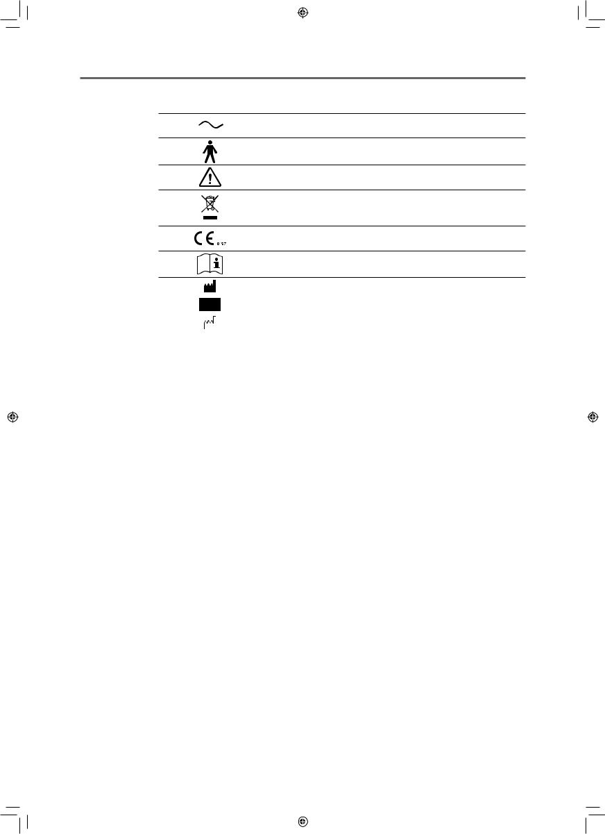
The following table describes the symbols and indications on the TX-20.
USA and Canada
Alternating current
Type B
Caution: Check the documentation provided.
MEDICAL EQUIPMENT
WITH RESPECT TO ELECRICAL SHOCK,
FIRE AND MECHANICAL HAZARDS ONLY
IN ACCORDANCE WITH UL 60601-1 AND CAN/CSA C22.2 NO. 601.1 41C4
Caution: Federal law (USA) restricts this device to sale by or on the order of a physician.
Year and month of manufacture |
Example: October 2010 |
|
|
Serial number in SIX digits |
Example: 123456 |
|
|
17
L-IE-5191C_TX-20.indb |
17 |
|
|
2013/07/18 |
13:10:15 |
|
|
||||
|
|
|
|
|
|
|
|
|
|
|
|
2 Safety
European Union
Alternating current
Type B
Caution: Check the documentation provided.
Product that WEEE directive, Directive on Waste Electrical and
Electronic Equipment, 2002/96/EC, requires separate collection.
This symbol shows compliance of the equipment with Directive 93/42/
EEC.
This symbol indicates that a User’s Manual is supplied with this equipment.
Manufacturer’s name and address
Serial number in SIX digits |
Example: 123456 |
|
|
Year and month of manufacture |
Example: October 2010 |
|
|
18
L-IE-5191C_TX-20.indb |
18 |
|
|
2013/07/18 |
13:10:17 |
|
|
||||
|
|
|
|
|
|
|
|
|
|
|
|
3Names of Parts
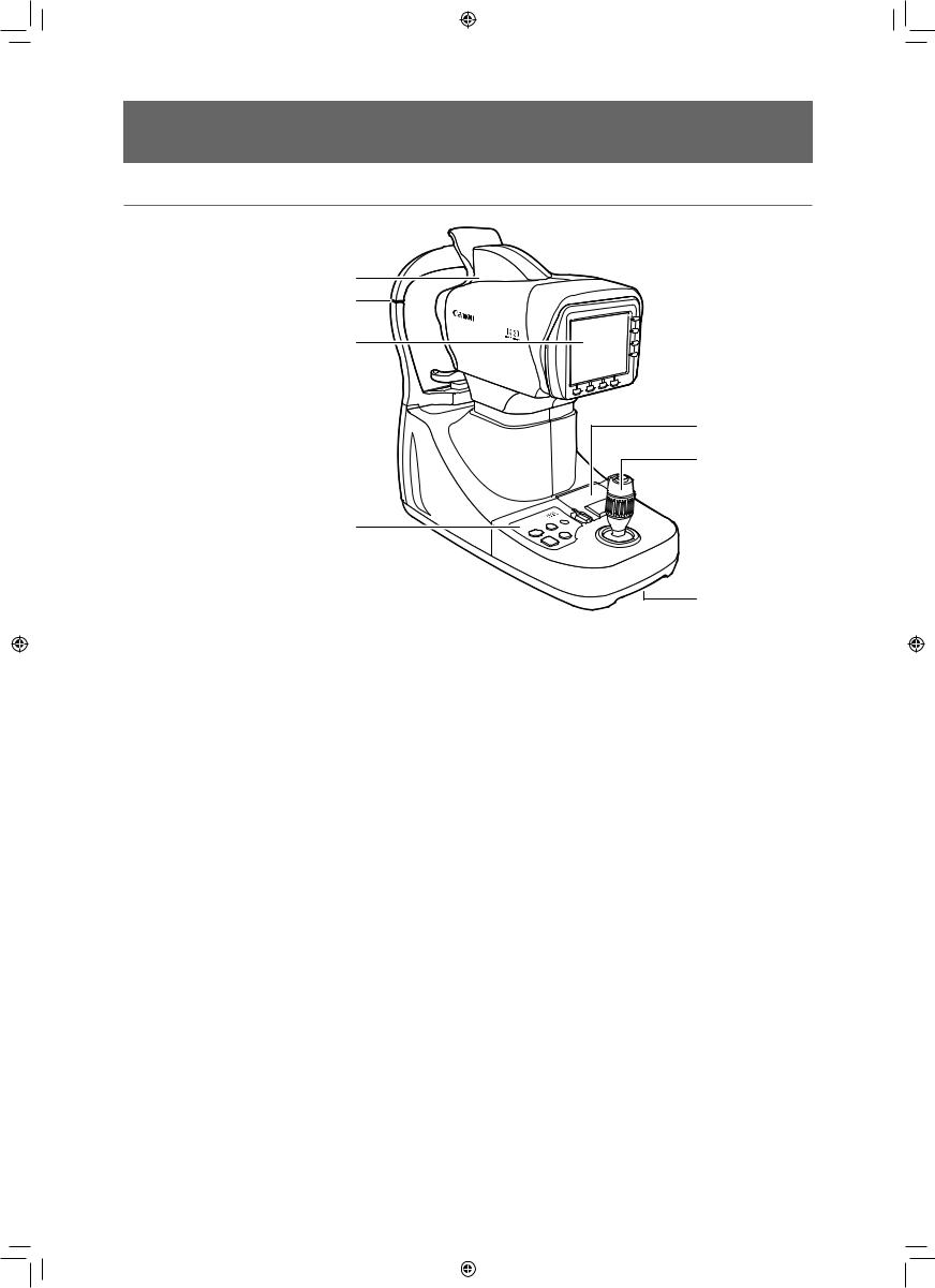
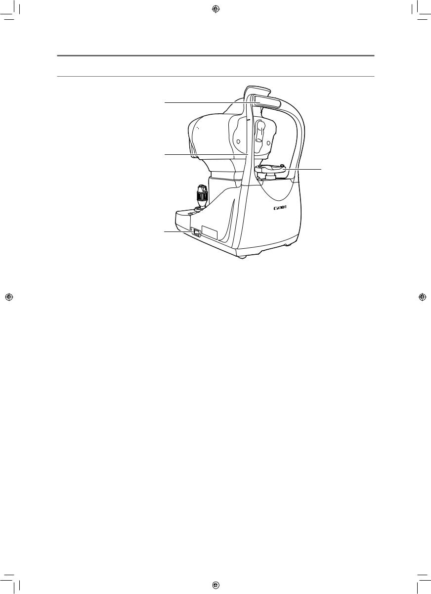
Main Unit (From the Examiner's Side)
1
2
3
5 |
6 |
4
|
|
|
7 |
1 |
Measurement unit |
5 |
Printer |
|
Measurement is done at this part. |
|
Prints the measurement results. |
2 |
Height adjustment mark |
6 |
Operation lever |
|
Align the patient's eye with this mark. |
7 |
Indentation for lifting |
3 LCD monitor
The patient's eye and various screens appear here.
4 Operation panel
Operations such as setting the nozzle position, chin rest height, and printing are done from here.
19
L-IE-5191C_TX-20.indb |
19 |
|
|
2013/07/18 |
13:10:17 |
|
|
||||
|
|
|
|
|
|
|
|
|
|
|
|
3 Names of Parts
Main Unit (From the Patient's Side)
1


 5 2
5 2 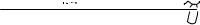

3
6
4
|
|
|
|
|
7 |
|
|
|
|
|
|||
1 |
Forehead rest |
5 |
External eye fixation lamp |
|||
|
Patient rests his/her forehead here to prevent |
|
Used if it is difficult to fix the patient's eye by using |
|||
|
patient's eye from moving. |
|
the internal eye fixation lamp. Fix on the eye that is |
|||
2 |
Nozzle |
|
not being measured. |
|||
|
|
|
|
|||
|
Blows air for observing or measuring the patient's |
6 |
Chin rest |
|||
|
eye. |
|
The patient’s chin is placed here. Raise or lower |
|||
3 |
Head rest |
|
the chin rest to set the appropriate height for the |
|||
|
patient’s eye(s). |
|||||
4 |
Power switch |
|
||||
7 |
Indentation for lifting |
|||||
|
Turns on the power for the main unit. |
|||||
|
|
|
|
|
||
20
L-IE-5191C_TX-20.indb |
20 |
|
|
2013/07/18 |
13:10:18 |
|
|
||||
|
|
|
|
|
|
|
|
|
|
|
|
3 Names of Parts
Bottom Side
1


 3 2
3 2 


4
1 |
|
RS-232C connector |
3 |
AC power connector |
|
|
Transfers measurement data to an external device. |
4 |
LAN connector |
|
|
Can be connected to a device that supports the |
|
Transfers measurement data to an external device. |
|
|
RS-232C standard. |
|
|
2 |
|
USB connector |
|
|
|
|
Reads patient ID from an external device. |
|
|
|
|
|
|
|
|
|
|
|
|
Using the RS-232C or LAN connector
See “Safety Precautions” (see page 12) and “Settings for Interface of Output of Measurements” (see page 64).
21
L-IE-5191C_TX-20.indb |
21 |
|
|
2013/07/18 |
13:10:18 |
|
|
||||
|
|
|
|
|
|
|
|
|
|
|
|
3 Names of Parts
Operation Panel
|
|
|
5 |
|
1 |
|
6 |
|
2 |
|
7 |
|
|
|
|
|
3 |
|
|
|
4 |
|
|
1 |
POWER lamp |
5 |
LIMITER button |
|
Lights when power is turned on. |
|
Sets the stop position to prevent the measurement |
2 |
R/L button |
|
unit from touching the patient. |
|
|
||
|
Switches between the patient's left and right eye |
6 |
CHECK button |
|
as the measurement unit moves automatically. |
|
Blows air from the nozzle. |
3 |
CHIN REST button |
7 |
Paper cover button |
Moves the chin rest up and down to align the height of the patient's eye.
4PRINT button
•Prints the measurement results. Sends the measurement results to an external device if one is connected and the settings have been done in advance.
•Pressing the PRINT button for 2 seconds or more prints or transmits the measured value and standard value for the number of measurements (see page 63).
•For the preparation for the next measurement, the settings change as shown below.
-Nozzle stop position: Releases the setting.
-Selection of eye fixation lamp: The internal eye fixation lamp is selected.
The external eye fixation lamp turns off and the internal eye fixation lamp flashes.
-Patient ID: The patient ID is cleared* (not entered state).
-Patient No: Counts up the patient numbers (however, according to settings).
-Display of measured value: Measured values are cleared* (not measured state).
-Measurement unit: Returns to the initial position.
*You can confirm the patient ID or measured value on the DATA screen until the measurement button is pressed.
22
L-IE-5191C_TX-20.indb |
22 |
|
|
2013/07/18 |
13:10:18 |
|
|
||||
|
|
|
|
|
|
|
|
|
|
|
|
3 Names of Parts
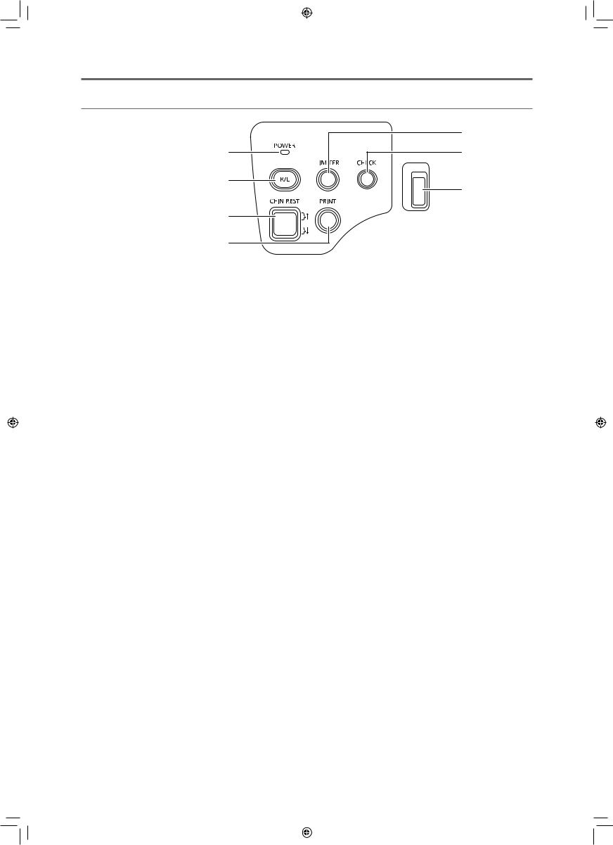
Operation Lever
2
3
1
4
1 |
Operation lever |
3 |
Measurement button |
|
Tilt the operation lever to move the measurement |
|
Starts the measurement. |
|
unit. |
4 |
Measurement unit’s vertical movement ring |
|
|
Tilt right or left: Moves slightly to right or left.
Tilt front or back: Moves slightly to the front or back.
Tilt past the maximum to the front, back, left, or right: Motion is great.
Turn the ring right and left to move the measurement unit up and down.
2 Alignment off button
While the button is pressed, the measurement unit does not move even if the operation lever is tilted. Use to adjust the angle of the operation lever without moving the measurement unit. For example, it can be used if the operation lever is at
an awkward and difficult-to-manipulate angle when aligning with the patient’s eye.
23
L-IE-5191C_TX-20.indb |
23 |
|
|
2013/07/18 |
13:10:18 |
|
|
||||
|
|
|
|
|
|
|
|
|
|
|
|
3 Names of Parts
Monitor Panel
1
1
1 Soft keys
The purpose of soft keys varies according to the assigned function. An icon on the monitor near the soft key indicates the purpose assigned to the soft key.
Pressing a soft key changes and sets functions, and changes the screen. In this manual, these soft keys are indicated by the name of their functions.
 Alignment
mode key
24
L-IE-5191C_TX-20.indb |
24 |
|
|
2013/07/18 |
13:10:19 |
|
|
||||
|
|
|
|
|
|
|
|
|
|
|
|
3 Names of Parts
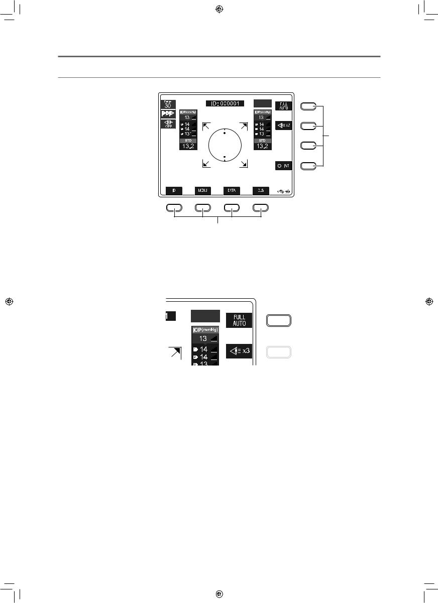
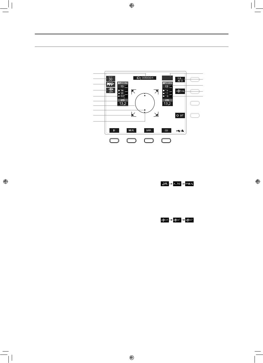
Measurement Screen
This screen appears when doing measurements.
You can set the measurement functions, show the most recent measurement data, and switch screens.
1 |
11 |
|
2 |
12 |
|
3 |
13 |
|
4 |
||
14 |
||
|
||
5 |
15 |
|
6 |
|
|
7 |
|
|
8 |
|
|
9 |
|
|
10 |
|
1Patient ID/Patient No.
2Measurement range
3Display order of measurement value
 : From highest to lowest reliability, 1 to 3.
 : From newest to oldest measurement, 1 to 3.
4LIMITER OFF mark
Indicates the LIMITER function is disabled.
11 Left/right eye indicator

 : Right eye

 : Left eye
12 Alignment mode setting
Press the adjacent alignment mode key to switch the alignment mode.
5 Measurement results history
Shows the results of measurements according to age or reliability.
6 Low reliability mark
This mark appears when reliability of the measurement is considered low as the result of the analysis of the measured value.
13 Most recent intraocular pressure
Shows the most recent measurement.
14 Measurement count setting
Press the adjacent measurement count key to switch the measurement count setting. Only enabled in full alignment mode.
7 Alignment circle
Mark for aligning vertical and horizontal position of patient's eye and measurement unit.
8 Corneal light point
A point that appears optically, indicating alignment of the position to measure in the patient’s eye and the measurement unit.
9 Measurement unit motion limit mark
Indicates measurement unit has moved to the limit position.
15 Level of received light
Indicates the amount of light received from light reflected from cornea when measuring intraocular pressure. The number of lines increases as the amount of received light increases.
If there is little received light, light reflected from the cornea may be obstructed by the eyelid or eyelashes. However, it is also affected by the corneal reflectivity of the patient.
10 Alignment guide
This guide is an index that shows the corneal light point. It only appears in manual alignment mode.
25
L-IE-5191C_TX-20.indb |
25 |
|
|
2013/07/18 |
13:10:20 |
|
|
||||
|
|
|
|
|
|
|
|
|
|
|
|
3 Names of Parts
19 20 21
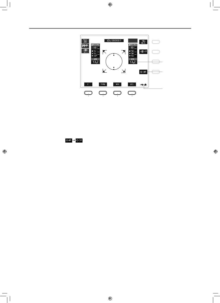
16 Intraocular pressure standard value
Representative intraocular pressure value that was statistically derived from measured values. Measured values with a low reliability mark are not used.
17 Eye fixation lamp
Press the adjacent eye fixation lamp key to switch the internal and external eye fixation lamps.
18 External device connection status
Shows the status of external device connection.
16
17
18
22
19 ID key
Press to switch to the PATIENT ID screen.
20 MENU key
Press to switch to the MENU screen.
21 DATA key
Press to switch to the DATA screen.
22 CLS key
Press to do the following.
•Nozzle stop position: Releases the setting.
•Selection of eye fixation lamp: The internal eye fixation lamp is selected.
The external eye fixation lamp turns off and the internal eye fixation lamp flashes.
•Patient ID: The patient ID is cleared* (not entered state).
•Patient No: Counts up the patient numbers (however, according to settings).
•Display of measured value: Measured values are cleared* (not measured state).
•Measurement unit: Returns to the initial position.
*You can confirm the patient ID or measured value on the DATA screen until the measurement button is pressed.
26
L-IE-5191C_TX-20.indb |
26 |
|
|
2013/07/18 |
13:10:20 |
|
|
||||
|
|
|
|
|
|
|
|
|
|
|
|
3 Names of Parts
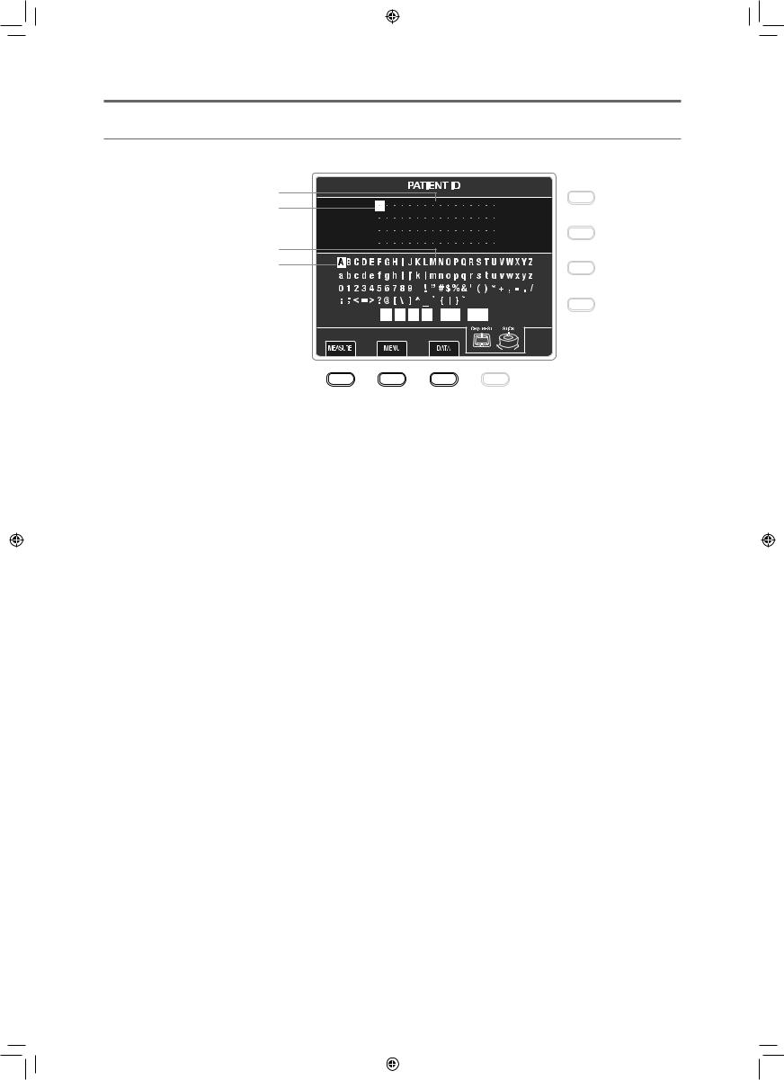
PATIENT ID Screen
This screen is used to input patient IDs.
1
2
3
4
|
5 |
|
|
|
|
|
|
|
|
|
|
|
|
|
|
|
|
|
6 |
|
|
|
|
|
|
|
|
|
|
|
|
|
|
|
|
|
|||||
|
|
|
|
|
|
|
|
|
|
|
|
|
|
|
|
|
7 |
|||
|
|
|
|
|
|
|
|
|
|
|
|
|
|
|
|
|
|
|||
|
|
|
|
|
|
|
|
|
|
|
|
|
|
|
|
|||||
|
|
|
|
|
|
|
|
|
|
|
|
|
|
|
|
|
|
|||
|
|
|
|
|
|
|
|
|
|
|
|
|
|
|
|
|
|
|
||
|
8 |
|
9 |
|
|
|
|
10 |
|
|
|
|
|
|
|
|||||
1 |
Patient ID area |
|
|
|
|
|
|
|
7 |
|
Operation reference guide |
|||||||||
|
The text selected from the list of characters |
|
|
|
Shows the types of buttons that can be operated |
|||||||||||||||
|
appears in the patient ID input field. |
|
|
|
|
|
|
|
|
|
|
in the PATIENT ID screen. Refer to "5 Types of |
||||||||
|
A maximum of 64 ASCII code characters can be |
|
|
|
Measurements" for operating procedures. |
|||||||||||||||
|
|
|
|
|
|
|
|
|
|
|||||||||||
|
input. |
|
|
|
|
|
|
|
8 |
|
MEASURE key* |
|||||||||
2 |
ID cursor |
|
|
|
|
|
|
|
|
|
|
Press to switch to the Measurement screen. |
||||||||
|
Shows the position where the patient ID can be |
9 |
|
MENU key* |
||||||||||||||||
|
edited. |
|
|
|
|
|
|
|
|
|
|
Press to switch to the MENU screen. |
||||||||
3 |
List of characters |
|
|
|
|
|
|
|
10 |
DATA key* |
||||||||||
List of characters that can be input for a patient ID.
Press to switch to the DATA screen.
4 Selection cursor
Select characters to input for a patient ID.
5 ID cursor movement commands
The ID cursor moves in the direction of the selected arrow.
6 ID delete command
[BS]: Deletes the character that is before the character specified by the ID cursor. However, if the ID cursor is specifying the first character, it deletes that character.
[CLS]: Deletes all the characters in the patient ID. The confirmation screen is displayed; select one of the following.
•[OK]: Deletes all text.
•[CANCEL]: Does not delete.
*By doing the settings in advance, if a patient ID has not been input when it is pressed, a message indicating that the patient ID has not been input is displayed (see page 68).
27
L-IE-5191C_TX-20.indb |
27 |
|
|
2013/07/18 |
13:10:20 |
|
|
||||
|
|
|
|
|
|
|
|
|
|
|
|
3 Names of Parts
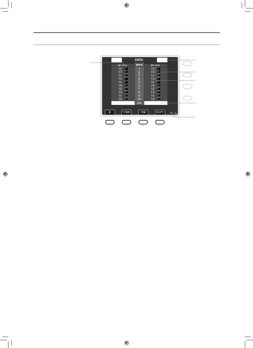
DATA Screen
This screen shows measurements.
2
1
3
4
5
6
7 |
8 |
9 |
10 |
1 Intraocular pressure
 : Shows measurements from highest to lowest reliability in order 1 to 10. (Measurement number: Up to 10)
 : Shows measurements from newest to oldest in order 1 to 10. (Measurement number: Up to 10)
7 ID key
Press to switch to the PATIENT ID screen.
8 MEASURE key
Press to switch to the Measurement screen.
9 MENU key
Press to switch to the MENU screen.
2Eye being measured
R: Right eye
L: Left eye
3 Level of received light
Indicates the amount of light received from light reflected from cornea when measuring intraocular pressure. The number of lines increases as the amount of received light increases.
If there is little received light, light reflected from the cornea may be obstructed by the eyelid or eyelashes. However, it is also affected by the corneal reflectivity of the patient.
10 DELETE key
Press to clear all the measurements.
The measurement values are deleted from the instrument’s memory.
4 Low reliability
This mark appears when the analysis of the results or reliability of the measurement is considered low. Measured values that have this mark are not included in the standard value calculation.
5 Intraocular pressure standard value
Representative intraocular pressure value that was statistically derived from measured values. Measured values with a low reliability mark are not used.
6 External device connection status
Shows the status of external device connection.
 : USB device is connected
 : Error has occurred in USB device connection
 : LAN is connected
 : RS-232C device is connected No display: No connection
28
L-IE-5191C_TX-20.indb |
28 |
|
|
2013/07/18 |
13:10:21 |
|
|
||||
|
|
|
|
|
|
|
|
|
|
|
|
3 Names of Parts
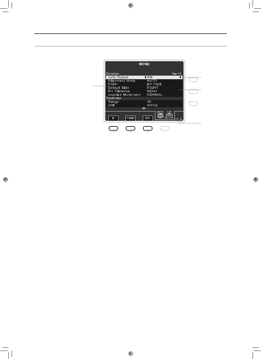
MENU Screen
Perform the settings for measurements, printing, and operating the measurement unit.
1 


 3
3
4
2
5
9
6 |
7 |
8 |
1 Settings tab
The items to set are grouped according to their purpose. Selected items are shown in orange.
 Measure tab: Settings for intraocular pressure measurements
 Print tab: Settings for printing with the builtin printer
 Input tab: Settings for inputting data from an external device
 Output tab: Settings for outputting data to an external device
 Patient tab: Settings for patient ID and patient No.
 Other tab: Settings for time, power saving mode, and the LCD, and shows information about the firmware.
2 Setting items
The setting items for each tab are displayed.
3Name of the selected tab
4Cursor
Shows the position of the selected setting value, setting item, and tab. They light orange when selected.
5 Settings
The settings for each setting item are displayed.
6 ID key
Press to switch to the PATIENT ID screen.
7 MEASURE key
Press to switch to the Measurement screen.
8 DATA key
Press to switch to the DATA screen.
9 External device connection status
Shows the status of external device connection.  : USB device is connected
 : Error has occurred in USB device connection
 : LAN is connected
 : RS-232C device is connected
No display: No connection
29
L-IE-5191C_TX-20.indb |
29 |
|
|
2013/07/18 |
13:10:22 |
|
|
||||
|
|
|
|
|
|
|
|
|
|
|
|
3 Names of Parts
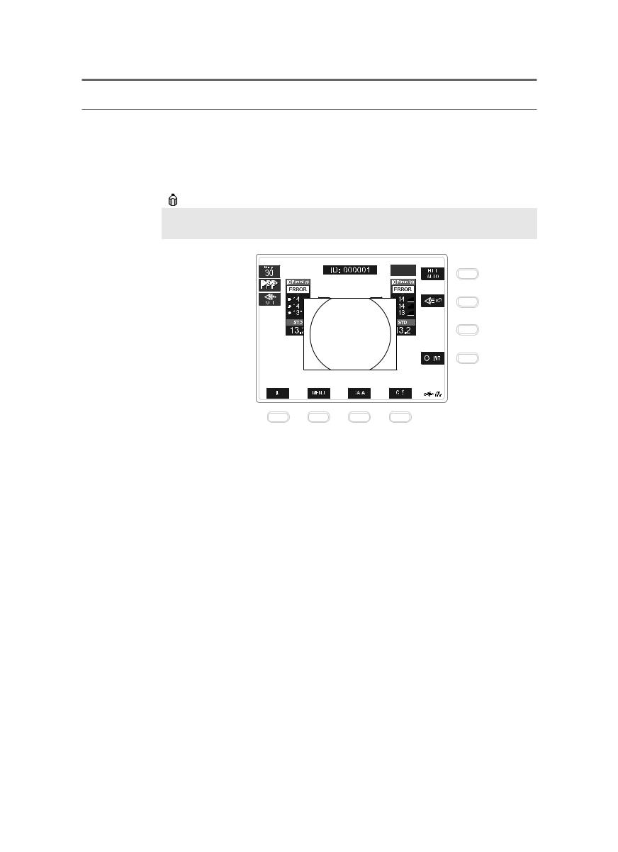
Screen that Appears When Measurement Fails
Anterior Segment Image Display Screen
If a measurement error occurs while measuring intraocular pressure, the anterior segment image from just prior to measuring is displayed. The anterior segment image disappears after 5 seconds or if you press a soft key.
If [OFF] is set for [Error Display] in the intraocular pressure measurement menu, the anterior segment image is not displayed (see page 62).
1 |
2 |
1 |
Eyelid warning line |
2 |
Cross mark |
Perform the measurement while the eyelid and eyelashes are above the warning line.
Displays the intraocular pressure measurement optical axis.
30
L-IE-5191C_TX-20.indb |
30 |
|
|
2013/07/18 |
13:10:22 |
|
|
||||
|
|
|
|
|
|
|
|
|
|
|
|
Loading...