


 Loading...
Ceiling-mount Hanger
Dispositif de suspension au plafond Soporte Colgante de Montaje en Techo Deckenmontagehalterung
Staffa di installazione per soffitto Plafondbevestiging
RS-CL07/RS-CL10
|
|
|
|
|
JPN |
|
|
|
|
Installation Manual |
ENG |
|
|
|
|
Manuel d’installation |
FRA |
|
|
|
|
Manual de Instalación |
SPA |
|
|
|
|
Installationsanleitung |
GER |
|
|
|
|
Manuale d’installazione |
ITA |
|
|
|
|
Installatiehandleiding |
NLD |
RS-CL07/RS-CL10
RS-CL07 WUX10 MarkII/SX7 MarkII/SX60/X7002009 12 ) RS-CL10 SX80 MarkII/SX800
|
● |
|
● RS-CL07/RS-CL10 |
|
|
|
|
|
● |
|
● |
|
● |
|
|
RS-CL07 (3.7kg)/RS-CL10 (4.1kg) |
||
|
RS-CL07 |
|
||
|
|
M5 12mm 4 |
|
|
|
|
M4 10mm 6 |
|
|
|
|
2 |
|
|
|
|
2 |
|
|
|
|
1 |
||
|
|
RS-CL10 |
|
|
|
|
M5 12mm 4 |
|
|
|
|
|
||
M4 10mm 5 |
|
|||
|
|
1 |
|
|
|
1 |
|
||
RS-CL07 |
RS-CL10 |
1 |
|
|
1 |
||||
|
|
|||
|
|
|
|
|
|
|
|
FRONT |
|
|
|
|
|
|
|
|
SCREW HOLE POSITION |
SCREW HOLE POSITION |
|
|
|
|
|
|
|
|
|
PROJECTION LENS CENTER |
|
|
|
|
|
|
|
|
TEMPLATE FOR RS CL10 |
|
|
|
|
|
|
|
|
|
CABLE HOLE MAX AREA |
|
|
|
|
|
|
|
|
|
SCREW HOLE POSITION |
SCREW HOLE POSITION |
|
RS-CL08/RS-CL09 RS-CL08 (2.2kg)/RS-CL09 (3.4kg)
●RS-CL08/RS-CL09
RS-CL08 |
RS-CL09 |
||
/ / |
/ / |
||
M5 12mm 4 |
M5 12mm 4 |
||
M3 10mm 1 |
M3 10mm 1 |
||
35 55cm |
55 95cm |
||
5cm |
5cm |
||
|
WUX10 MarkII 5.0kg |
SX7 MarkII/X700 4.8kg SX60 4.6kg |
|
SX80 MarkII 5.2kg |
SX800 5.0kg |
||
|
|||
|
● |
|
|
|
P.1 |
|
|
|
● |
|
● |
|
|
RS-CL07 WUX10 MarkII
168 mm
|
ℓ |
|
|
|
|
|
178 mm |
62 mm |
|
346 mm |
284 mm |
|
|
|
 41 mm 249 mm
178 mm |
168 mm |
62 mm |
|
16:10
( ℓ )
RS-CL07 |
RS-CL08 |
RS-CL09 |
25 cm |
60 cm 80 cm |
80 cm 120 cm |
|
|
40 |
60 |
80 |
100 |
150 |
180 |
200 |
250 |
300 |
|||
× cm |
|
86×54 |
129×81 |
172×108 |
215×135 |
323×202 |
388×342 |
431×269 |
538×337 |
646×404 |
|||
m |
1.2 |
1.8 |
2.4 |
3.0 |
4.5 |
5.4 |
6.1 |
7.6 |
9.1 |
||||
m |
1.8 |
2.6 |
3.5 |
4.4 |
6.7 |
8.0 |
8.9 |
- |
- |
||||
● |
|
|
|||||||||||
|
|
|
|
|
|
|
|
|
|||||
100 mm 100 mm |
|
|
|
|
|
|
|
|
|
|
|||
80 mm |
|
|
|
100 mm |
|
|
|
|
|
|
|
|
|
|
|
|
|
|
|
|
|
|
|
|
|||
|
|
|
|
|
|
|
|
|
|
|
|||
80 mm |
|
|
|
100 mm |
|
|
|
|
|
|
|
|
|
|
|
|
|
|
|
|
|
|
|
|
|||
|
|
|
|
|
|
|
|
|
|||||
80 mm 80 mm |
|
|
|
|
|
|
|
|
|
|
|||
RS-CL07 SX7 MarkII/SX60/X700
168 mm
|
ℓ |
|
|
H2 |
|
H1 |
178 mm |
|
346 mm |
|
|
|
178 mm 168 mm |
|
62 mm |
|
|
|
|
|
249 mm |
62 mm |
mm |
266 mm |
|
|
41 |
|
|
|
|
|
|
|
|
|
|
|
|
|
|
|
|
|
|
|
|
4:3 |
|
|
|
|
|
|||
|
|
|
|
|
|
|
|
|
|
|
|
|
|
|
|
|
|
|
|
|
|
|
|
|
|
|
|
|
|
|
|
|
|
|
( ℓ )
RS-CL07 |
RS-CL08 |
RS-CL09 |
25 cm |
60 cm 80 cm |
80 cm 120 cm |
|
40 |
60 |
80 |
100 |
150 |
182 |
200 |
250 |
300 |
× cm |
81×61 |
122×91 |
163×122 |
203×152 |
305×229 |
370×277 |
406×305 |
508×381 |
610×457 |
m |
1.2 |
1.8 |
2.4 |
3.0 |
4.5 |
5.4 |
5.9 |
7.4 |
8.9 |
m |
2.0 |
2.9 |
3.9 |
4.9 |
7.4 |
9.0 |
- |
- |
- |
H1 cm |
55 |
82 |
110 |
137 |
206 |
250 |
274 |
343 |
411 |
H2 cm |
6 |
9 |
12 |
15 |
23 |
28 |
30 |
38 |
46 |
●
RS-CL10 SX80 MarkII/SX800 |
164 mm |
|
|
|
ℓ |
|
mm |
|
|
|
|
|
|
|
249 |
|
|
|
|
|
178 mm |
59 mm |
mm |
|
342 mm |
332 mm |
|
|
45 |
||
|
|
|
|
|
|
|
|
|
|
|
178 mm |
164 mm |
|
|
|
|
|
|
|
59 mm |
|
|
|
|
|
|
|
|
|
|
|
|
|
|
4:3 |
|
|
|
|
|
|
|
|
|
|
|
|
|
|
|
|
|
|
|
|
|
|
|
|
|
|
|
|
|
|
( ℓ ) |
|
|
|
|
|
|
|||
RS-CL10 |
|
RS-CL08 |
|
RS-CL09 |
|
|
|
||
25 cm |
|
60 cm 80 cm |
|
80 cm 120 cm |
|
|
|
||
|
|
|
|
|
|
|
|
|
|
|
40 |
60 |
80 |
100 |
150 |
182 |
200 |
250 |
300 |
× cm |
81×61 |
122×91 |
163×122 |
203×152 |
305×229 |
370×277 |
406×305 |
508×381 |
610×457 |
m 1.2 |
1.8 |
2.4 |
3.0 |
4.5 |
5.4 |
5.9 |
7.4 |
8.9 |
|
m 2.0 |
2.9 |
3.9 |
4.9 |
7.4 |
9.0 |
- |
- |
- |
|
● |
|
|
|||||||
|
|
|
|
|
|
|
|
|
|
100 mm 100 mm |
|
|
|
|
|
|
|
|
|
80 mm |
100 mm |
|
|
|
|
|
|
|
|
80 mm |
100 mm |
|
|
|
|
|
|
|
|
80 mm 80 mm |
|
|
|
|
|
|
|
|
|
|
|
|
|
|
|
M5 4 |
||
|
||
|
|
1
●
●
2 |
|
|
|
M134
●
● M13
3
M4 RS-CL07 6 RSCL10 5
WUX10 MarkII/SX7 MarkII/SX60/X700
SX80 MarkII/SX800
4
RS-CL10(A)(B)
RS-CL10(C)(D)
●2
5
6
M5 4
 C
C
D
B
A
WUX10 MarkII/SX7 MarkII/SX60/X700
 C
C
D
B
 A
A
SX80 MarkII/SX800
7 |
|
WUX10 MarkII/SX7 MarkII/SX60/X700 |
|
|
|
|
(A) |
|
|
|
|
|
M5 (B) 4 |
|
|
● |
|
|
● B P.11 |
|
|
|
|
8 |
A |
|
|
|
B |
|
|
|
|
|
|
|
|
|
B
P.11
RS-CL08 RS-CL09
M5 4
|
● 2 |
|
|
|
|
|
1 |
|
|
|
|
|
2 |
|
|
||
|
|
|
|
|
|
|
|
|
|
|
|
|
|
|
|
|
|
|
|
ℓ |
|
|
|
|
RS-CL08 |
RS-CL09 |
|
a |
|
|
|
b |
|||
|
a |
60 cm |
80 cm |
c |
|
|
d |
||||
|
b |
65 cm |
85 cm |
||
|
e |
||||
|
|
||||
|
c |
70 cm |
90 cm |
f |
|
|
g |
||||
|
d |
75 cm |
95 cm |
ℓ h |
|
|
i |
||||
|
e |
80 cm* |
100 cm |
|
|
|
f |
|
105 cm |
|
|
|
g |
|
110 cm |
|
|
|
h |
|
115 cm |
|
|
|
i |
|
120 cm* |
|
|
* 2 |
ℓ ' |
|
|||
|
|
||||
ℓ' 4.1cm (WUX10 MarkII/SX7 MarkII/SX60/X700)/4.5cm (SX80 MarkII/SX800) |
|
|
|||
1 |
|
|
|
|
|
|
P.5 |
|
|
|
|
2 |
|
|
|
|
|
|
P.5 1 |
|
|
|
|
3
P.5 2
4 P.5 3
5
P.6 4
6 |
|
|
|
|
|
|
M5 4 |
|
|
|
|
|
● |
|
|
|
|
|
180 |
|
|
|
|
|
|
|
7
おいたM5 4
8 |
|
|
|
|
B |
|
(A) |
|
|
|
|
|
M5 (B)4 |
|
|
B P.11 |
|
|
|
A |
|
|
|
|
7 |
|
|
8 |
|
B
9
②
延長用パイプに付属のM3 1
P.11
10

|
|
|
A |
|
|
|
|
B |
|
C |
D |
(A)2
5° |
5° |
B 4 C 2 |
|
|
|
|
|
|
5° |
|
(C) B |
||
|
||
|
20° |
(D)4
(D)
10° |
11 |
|
● |
|
|
|
● |
|
|
|
● P.11 |
|
|
ねじA 2
じて蝶ねじ(A)
RS-CL07
A
AA
RS-CL10
AA

|
|
|
|
|
|
|
|
|
|
|
|
|
|
RS-CL07 |
RS-CL10 |
|
|
|
|
|
|
5° |
5° |
|
|
|
|
|
|
5° 20° |
5° 20° |
|
|
|
|
|
|
± 5 ° |
± 5 ° |
|
|
|
|
|
222.7mm× 281.5mm× 175.8mm |
310.5mm× 276.2mm× 178.2mm |
|
|
|
|
|
|
3.7kg |
4.1kg |
|
|
|
|
|
12
Canon Ceiling-mount Hanger
RS-CL07/RS-CL10 Assembly/Installation Manual
Applicable projector models |
RS-CL07 WUX10 MarkII/SX7 MarkII/SX60/X700 |
(As of December 2009) |
RS-CL10 SX80 MarkII/SX800 |
The Ceiling-mount Hanger is used to secure the projector to the ceiling.
●Ask an expert builder to install the Ceiling-mount Hanger.
●The Ceiling-mount Hanger RS-CL07/RS-CL10 can be used exclusively for Canon projectors
 (models listed above). It cannot be used for any other equipment. Do not place/hang any other Caution objects on/from this Ceiling-mount Hanger. Do not let children hang from it.
●Assemble and install this Ceiling-mount Hanger correctly in accordance with this manual.
●Make sure to tighten screws securely. Do not remodel any part.
●For details on cautions on using the projector, refer to the User's Manual that came with the projector.
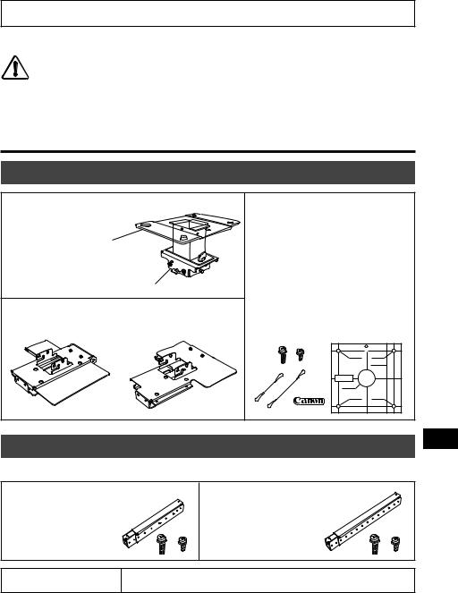
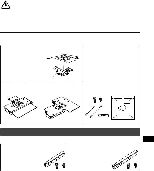
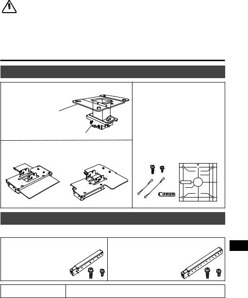
Parts Lineup
Supplied Parts |
Weight: RS-CL07 (3.7 kg/8.2 lbs)/RS-CL10 (4.1 kg/9.1 lbs) |
|
|
Ceiling-mount bracket and Joint fitting
Ceiling-mount bracket 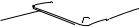


* The Ceiling-mount bracket must
be separated from the Joint fitting, |
|
before installation. |
Joint fitting |
|
Ceiling-mount bracket
RS-CL07 RS-CL10
RS-CL07
M5 screws (12 mm/0.5") : 4 pcs.
M4 screws (10 mm/0.4") : 6 pcs. Anti-fall wires: 2 pcs.
Canon logo seal: 2 sht.
Template sheet for a ceiling-mount hole: 1 sht.
RS-CL10
M5 screws (12 mm/0.5") : 4 pcs.
M4 screws (10 mm/0.4") : 5 pcs. Anti-fall wire (short) : 1 pc. Anti-fall wire (long) : 1 pc. Canon logo seal: 1sht.
Template sheet for ceiling mount hole: 1 sht.
|
|
|
FRONT |
|
|
SCREW HOLE POSITION |
SCREW HOLE POSITION |
|
|
|
PROJECTION LENS CENTER |
|
|
TEMPLATE FOR RS CL10 |
|
|
|
CABLE HOLE MAX AREA |
|
|
|
SCREW HOLE POSITION |
SCREW HOLE POSITION |
Extension pipe RS-CL08/RS-CL09 (option) Weight:RS-CL08(2.2kg/4.9lbs)/RS-CL09(3.4kg/7.5lbs)
●Use an optional extension pipe (RS-CL08/RS-CL09) according to the ceiling height. For details, contact our local agent.
/RS-CL08
Outer/inner pipes and outer/inner covers M5 screw (12 mm/0.5") : 4 pcs.
M3 screw (10 mm/0.4") : 1 pc.
The length is adjustable between 35 cm/1.1' and 55 cm/1.9' in steps of 5 cm/2".
RS-CL09
Outer/inner pipes and outer/inner covers M5 screw (12 mm/0.5") : 4 pcs.
M3 screw (10 mm/0.4") : 1 pc.
The length is adjustable between 55 cm/1.9' and 95 cm/3.1' in steps of 5 cm/2".
Projector weight |
WUX10 MarkII: 5.0 kg/11.02 lbs SX7 MarkII/X700: |
4.8 kg/10.6 lbs |
|
SX60: 4.6 kg/10.1 lbs SX80 MarkII: 5.2 kg/11.4 lbs |
SX800: 5.0 kg/11.02 lbs |
||
|
Mounting Position
The connection between projector screen size and projection distance is shown below.
Install the projector straight in front of the screen. Mounting the projector sideways distorts the projected image.
●Before mounting the Ceiling-mount Hanger, be sure to check the strength of the ceiling. The ceiling should be strong enough to support the projector and Ceiling-mount Hanger (and optional
extension pipe). If the ceiling is not strong enough, be sure to reinforce it (For weight of projector,
Caution ceiling-mount hanger, and extension pipe, refer to page 1).
● Be sure to install the Ceiling-mount Hanger to the ceiling which is flat and level. Do not install it to rough or un-level ceiling. Do not let children hang from it.
● To prevent falling caused by earthquake or vibration, take anti-fall measures using tension wires or the like for installation.
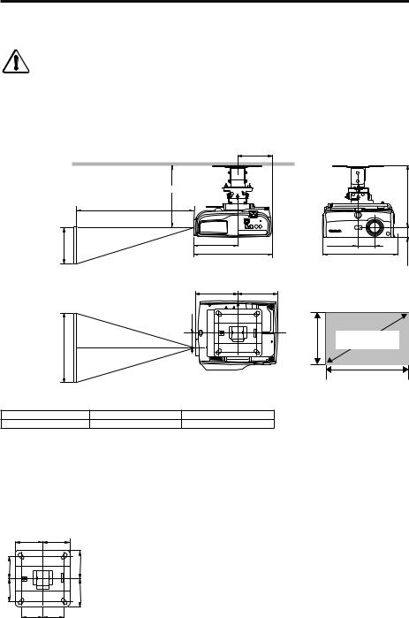
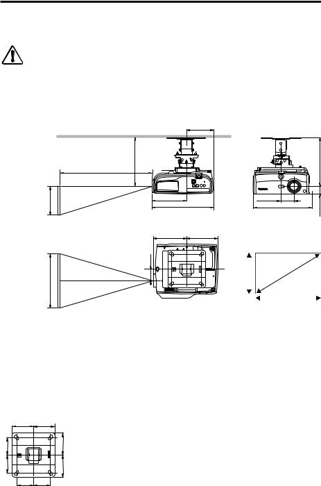
RSCL07 : WUX10 MarkII
168 mm
l
Projection Distance
Height |
178 mm |
62 mm |
|
346 mm |
284 mm |
||
|
|||
|
Side view |
Front view |
 41 mm 249 mm
Width
178 mm |
168 mm |
62 mm |
|
Top view
|
|
|
|
|
|
|
|
|
|
|
|
|
|
Height |
|
16:10 |
|
|
||
|
|
Screen size |
|
|
||
|
|
|
|
|
|
|
|
|
|
|
|
|
|
|
|
|
|
|
|
|
|
|
|
|
|
|
|
|
|
|
|
Width |
|
|
Distance from ceiling to lens center (l)
RS-CL07/RS-CL10 |
When RS-CL08 is used |
When RS-CL09 is used |
25 cm/0.8' |
60 cm/2.0' to 80 cm/2.6' |
80 cm/2.6' to 120 cm/3.9' |
Screen Size and Projection Distance
Screen size (inch) |
40 |
60 |
80 |
100 |
150 |
180 |
200 |
250 |
300 |
(Width x height cm) |
86×54 |
129×81 |
172×108 |
215×135 |
323×202 |
388×342 |
431×269 |
538×337 |
646×404 |
Projection distance (Zoom max.) |
1.2 m/3.9' |
1.8 m/5.9' |
2.4 m/7.9' |
3.0 m/9.8' |
4.5 m/14.8' |
5.4 m/17.7' |
6.1 m/20.0' |
7.6 m/24.9' |
9.1 m/29.9' |
Projection distance (Zoom min.) |
1.8 m/5.9' |
2.6 m/8.5' |
3.5 m/11.5' |
4.4 m/16.1' |
6.7 m/22.0' |
8.0 m/26.3' |
8.9 m/29.2' |
- |
- |
● The distance can be adjusted within the range shown above by changing the screen size using the zoom function of the projector.
Ceiling-mount bracket
100 mm 100 mm
80 mm |
100 mm |
80 mm |
100 mm |
|
80 mm 80 mm |
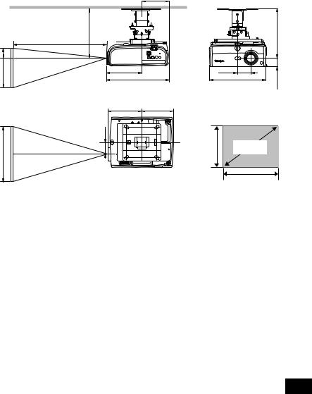
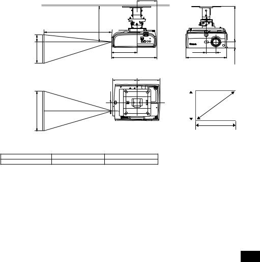
RS-CL07 : SX7 MarkII/SX60/X700 |
|
168 mm |
|
l |
|
Projection Distance |
|
|
H2 (Height) |
|
|
H1 (Height) |
178 mm |
|
|
346 mm |
|
|
Side view |
|
|
178 mm |
168 mm |
|
62 mm |
|
Width |
|
|
|
|
Top view |
62 mm
266 mm
Front view
4:3 Screen size
41 mm 249 mm
Distance from ceiling to lens center (l)
RS-CL07/RS-CL10 |
When RS-CL08 is used |
When RS-CL09 is used |
25 cm/0.8' |
60 cm/2.0' to 80 cm/2.6' |
80 cm/2.6' to 120 cm/3.9' |
Screen Size and Projection Distance
Screen size (inch) |
40 |
60 |
80 |
100 |
150 |
182 |
200 |
250 |
300 |
(Width x height cm) |
81×61 |
122×91 |
163×122 |
203×152 |
305×229 |
370×277 |
406×305 |
508×381 |
610×457 |
Projection distance (Zoom max.) |
1.2 m/3.9' |
1.8 m/5.9' |
2.4 m/7.9' |
3.0 m/9.8' |
4.5 m/14.8' |
5.4 m/17.7' |
5.9 m/19.4' |
7.4 m/24.2' |
8.9 m/29.2' |
Projection distance (Zoom min.) |
2.0 m/6.6' |
2.9 m/9.6' |
3.9 m/12.9' |
4.9 m/16.1' |
7.4 m/24.2' |
9.0 m/29.5' |
- |
- |
- |
H1 |
55 cm/1.8' |
82 cm/2.7' |
110 cm/3.6' |
137 cm/4.5' |
206 cm/6.8' |
250 cm/8.2' |
274 cm/9.0' |
343 cm/11.3' |
411 cm/13.5' |
H2 |
6 cm/0.2' |
9 cm/0.3' |
12 cm/0.4' |
15 cm/0.5' |
23 cm/0.8' |
28 cm/0.9' |
30 cm/1.0' |
38 cm/1.2' |
46 cm/1.5' |
● The distance can be adjusted within the range shown above by changing the screen size using the zoom function of the projector.
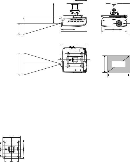
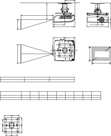
RS-CL10 SX80 MarkII/SX800 |
164 mm |
|
|
|
|
|
l |
|
Projection Distance |
Height |
178 mm |
|
342 mm |
|
Side view |
|
249 mm |
|
59 mm |
mm |
|
332 mm |
||
45 |
||
Front view |
||
|
178 mm |
164 mm |
|
|
59 mm |
|
|
|
Width |
|
Height |
4:3 |
|
Screen size |
||
|
|
|
|
Top view |
|
Width |
|
|
|
|
|
Distance from ceiling to lens center (l)
RS-CL07/RS-CL10 |
When RS-CL08 is used |
When RS-CL09 is used |
25 cm/0.8' |
60 cm/2.0' to 80 cm/2.6' |
80 cm/2.6' to 120 cm/3.9' |
Screen Size and Projection Distance
Screen size (inch) |
40 |
60 |
80 |
100 |
150 |
182 |
200 |
250 |
300 |
(Width x height cm) |
81×61 |
122×91 |
163×122 |
203×152 |
305×229 |
370×277 |
406×305 |
508×381 |
610×457 |
Projection distance (Zoom max.) |
1.2 m/3.9' |
1.8 m/5.9' |
2.4 m/7.9' |
3.0 m/9.8' |
4.5 m/14.8' |
5.4 m/17.7' |
6.0 m/19.7' |
7.6 m/24.9' |
9.1 m/29.9' |
Projection distance (Zoom min.) |
1.7 m/5.6' |
2.6 m/8.5' |
3.5 m/11.5' |
4.4 m/14.4' |
76.6 m/21.7' |
8.0 m/26.3' |
8.9 m/29.2' |
- |
- |
● The distance can be adjusted within the range shown above by changing the screen size using the zoom function of the projector.
Ceiling-mount bracket
100 mm 100 mm
80 mm |
100 mm |
80 mm |
100 mm |
|
80 mm 80 mm |
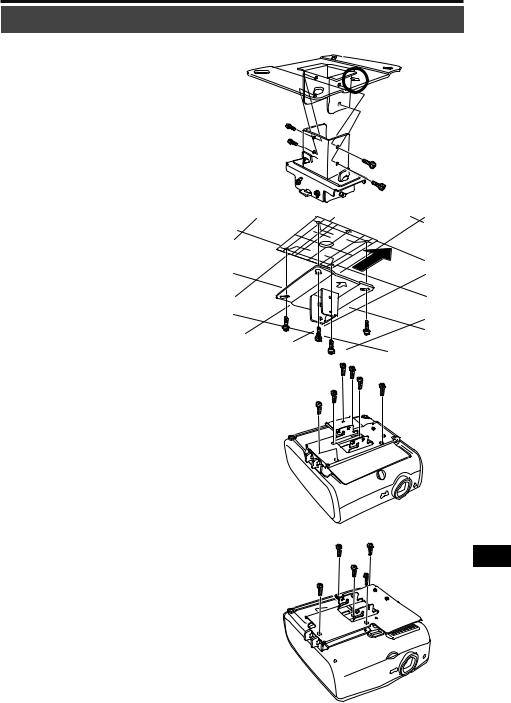
Assembly and Installation
Installation to flat and level Ceiling
Preparation:
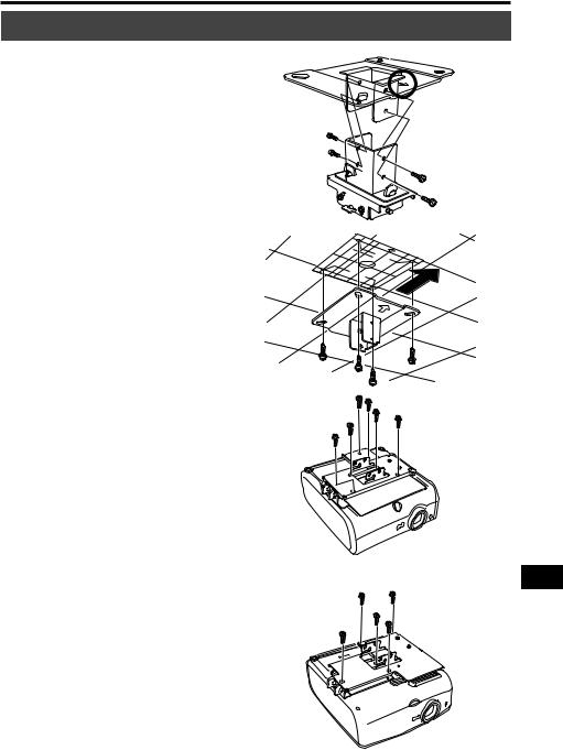
Separate the Joint fitting from the
Ceiling-mount bracket temporarily
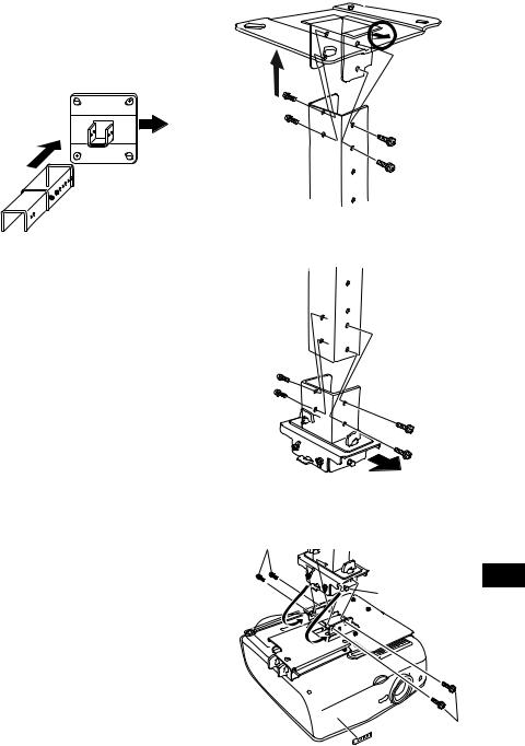
Remove four M5 screws to separate Joint fitting from the Ceiling-mount bracket.
1 Make a hole in the ceiling
Make a hole in the ceiling to install the Ceiling-mount bracket and cables.
● When determining the hole position, use the supplied template sheet.
● The direction to the screen is indicated on the template sheet.
2 Secure the Ceiling-mount bracket to the ceiling
Use four M13 screws, to secure the Ceilingmount bracket to the ceiling with the arrow facing toward the screen.
● Before securing the Ceiling-mount bracket, be sure to remove the template sheet.
● The M13 screws are not included in the supplied parts. Prepare the M13 screws suitable for the ceiling structure.
3 Attach the Base bracket to the projector
Secure with the supplied M4 screws (RS-
CL07: 6 pcs.; RS-CL10: 5 pcs.).
Direction to the screen
Direction to the screen
WUX10 MarkII/SX7 MarkII/SX60/X700
SX80 MarkII/SX800
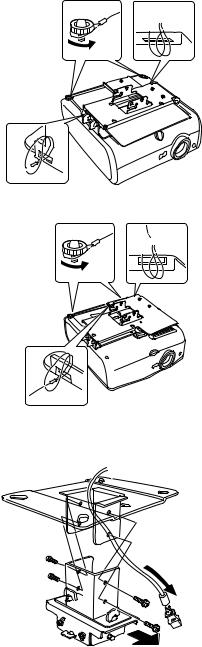
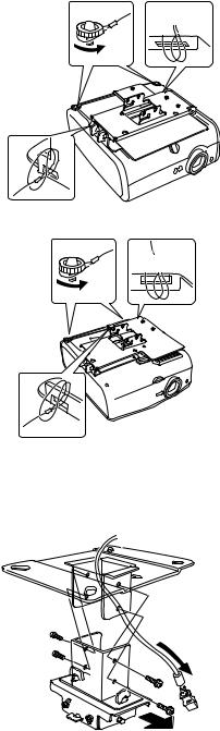
4 Attach the anti-fall wires
1Loosen the left and right adjusting feet of the projector.
2Pass one end of the anti-fall wire (longer wire for RS-CL10) into the square hole (A) on the Base bracket, and then fasten the other end to the right adjusting foot (B).
3Pass one end of the anti-fall wire (shorter wire for RS-CL10) into the square hole (C), and then fasten the other end to the left adjusting foot (D).
4Tighten the left and right adjusting feet to secure the anti-fall wires.
● Be sure to attach both anti-fall wires.
5 Pull cables out of the cable hole in the ceiling
6 Attach the Joint fitting to the
Ceiling-mount bracket
Secure the Ceiling-mount bracket using the four M5 screws removed during preparation.
 C
C
D
B
 A
A
WUX10 MarkII/SX7 MarkII/SX60/X700
 C
C
D
B
A
SX80 MarkII/SX800
Direction to the screen
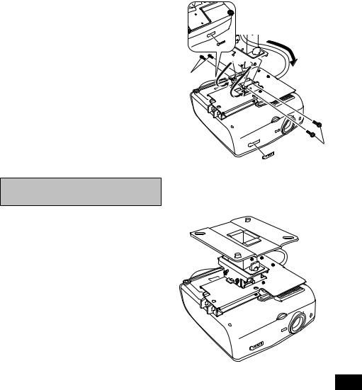
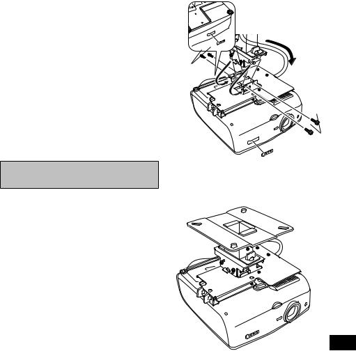
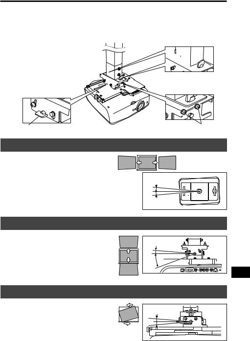
7 Hook the Base bracket to the Joint fitting and secure it temporarily
Hook the Base bracket on the protrusion (A) of the Joint fitting, and secure it temporarily using the four supplied M5 screws (B).
●Pull out the cables as shown.
●Be sure to secure screws (B) tightly after making the adjustment discussed in "Adjusting the Projection Angle " (page 11).
8 Connect cables
1 Connect cables to the projector.
2 Affix the supplied Canon logo seal as shown.
After completion of installation, adjust the projection angle (page 11).
For WUX10 MarkII/SX7 MarkII/SX60/X700, affix an additional seal at the back.


 A
A
B
B
Installation to a High Ceiling
Use optional extension pipe RS-CL08 or RS-CL09 for high ceiling.
Preparation:
Adjust the pipe length according to the ceiling height
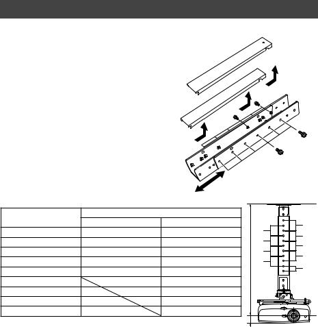
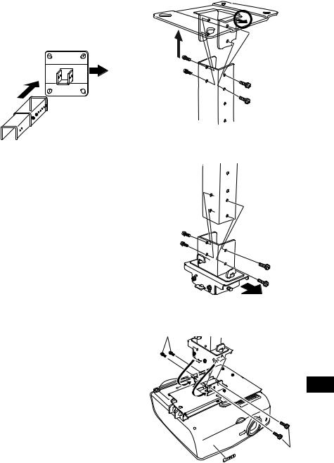
1 Remove the covers of outer and inner pipes by slightly sliding them and lift up as shown.
2 Remove four M5 screws from the |
|
sides of the outer pipe, adjust the inner |
|
pipe length according to the projector |
|
installation height, and then secure the |
|
four M5 screws. |
1 |
|
●When attaching screws in step 2, insert the screws and leave an unused screw hole between them. When the extension pipe is stretched to its maximum length, insert the screws in two adjacent screw holes.
Pipe extension length
Mounting hole position |
Distance from ceiling to lens axis (l) |
||
RS-CL08 |
RS-CL09 |
||
|
|||
a |
60 cm/2.0' |
80 cm/2.6' |
|
b |
65 cm/2.1' |
85 cm/2.8' |
|
c |
70 cm/2.3' |
90 cm/3.0' |
|
d |
75 cm/2.5' |
95 cm/3.1' |
|
e |
80 cm/2.6'* |
100 cm/3.3' |
|
f |
|
105 cm/3.4' |
|
g |
|
110 cm/3.6' |
|
h |
|
115 cm/3.8' |
|
i |
|
120 cm/3.9'* |
|
*To use the extension pipe with it extended to the maximum length, secure it by inserting screws in the two adjacent screw holes.
l' = 4.1 cm/0.14' (WUX10 MarkII/SX7 MarkII/SX60/X700) /4.5 cm/0.15' (SX80 MarkII/SX800)
1 Separate the Joint fitting from the
Ceiling-mount bracket temporarily
Preparation on page 5
2 Make a hole in the ceiling
Step 1 on page 5
3 Secure the Ceiling-mount bracket to the ceiling Step 2 on page 5
4 Attach the Base bracket to the projector Step 3 on page 5
5 Attach the anti-fall wires
Step 4 on page 6
2 
|
b |
a |
|
|
c |
||
|
d |
||
|
e |
||
|
f |
||
l |
g |
||
h |
|||
|
i |
||
|
|
l'
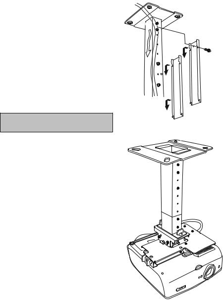
6 Attach the top of the extension pipe to the Ceiling-mount bracket
Secure to the extension pipe using the four supplied M5 screws.
●The open end of the pipe should face the open end of the Ceiling-mount bracket as shown.
Direction to the screen
Direction to the screen
7 Attach the Joint fitting to the bottom of the extension pipe
Use the four M5 screws removed from the Ceiling-mount bracket during preparation.
8 Hook the Base bracket on the projections of the Joint fitting and secure it temporarily
1Hook the Base bracket on the protrusion
(A)of the Joint fitting, and secure it temporarily using the four supplied M5 screws (B).
Tighten the screws (B) after making the adjustment in "Adjusting the Projection Angle" (page 11).
2 Affix the supplied Canon logo seal. For the direction and position of the logo seal, see the refer to step 8 on page 7.
Direction to the screen
B


 A
A
B
9 Put the cables in to the pipe and attach the covers
1 Pull the cables out of the cable hole in the ceiling.
2 Put the cables inside the pipe.
3 Close the inner cover of the pipe and then close outer cover of the pipe. Secure to the extension pipe using the supplied M3 screw.
4 Connect the cables to the projector.
After completion of installation, adjust the projection angle (page 11).
10
Adjust the Projection Angle
Turn on the projector, project an image, and then adjust the projection angle and screen slant angle.
●After completion of adjustment, tighten the screws and check that every fitting is secured firmly.
●Be sure to hold the projector from falling until the Ceiling-mount bracket and Base bracket are secured firmly.
Adjust the horizontal projection angle.


 A
A
 Adjust the screen slant angle. Adjust the vertical projection angle.


 B
B
C D
Adjust the horizontal projection angle
1Loosen two wing screws (A). Move the projector horizontally to adjust the horizontal projection angle.
2When the projector is correctly positioned, tighten the wing screw.
5° |
5° |
Adjust the vertical projection angle
1 First loosen four screws (B) and then loosen two wing screws (C). Move the projector vertically to adjust the vertical projection angle.
2When the projector is correctly positioned, first tighten the wing screws (C) and next tighten the four screws (B).
5° |
20° |
Adjust the screen inclination
1Loosen four screws (D), and then adjust the slant angle of the projector.
2When the projector is correctly positioned, tighten the four screws (D).
10° |
11 |
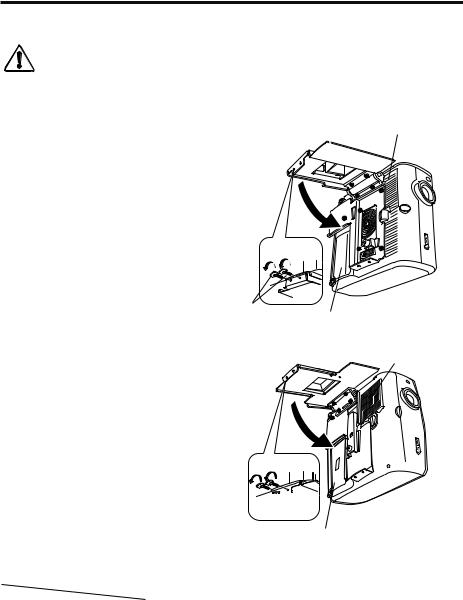
Replacing the Lamp and Cleaning/Replacing the Air Filter
This Ceiling-mount Hanger allows you to replace the lamp and clean/replace the air filter without dismounting the projector.
●Before replacing the lamp or cleaning/replacing the air filter, be sure to turn off the projector and unplug the power cord from the AC outlet and that the projector is cooled sufficiently.
 ● For details on how to replace the lamp and clean/replace the air filter, refer to the User's Manual Caution that came with the projector.
●Check the projection angle and the screen slant angle after replacing the lamp. For details on how to adjust the angles, refer to page 11.
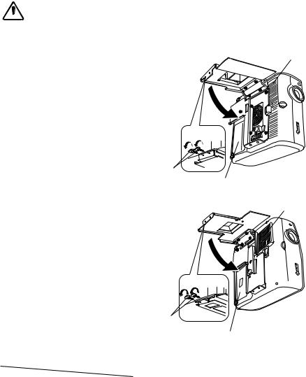
1 Hold the projector, and remove two wing screws (A) and open the Base bracket slowly.
2 Replace the lamp, or clean or replace the air filter.
3 After completion of replacement of the lamp or cleaning/replacement of the air filter, lift up the projector, and close the Base bracket then tighten the wing screw
(A).
RS-CL07 |
Filter cover |
|
1
AA
Lamp cover
RS-CL10
Filter cover
1
AA
|
|
|
|
|
Lamp cover |
|
Specifications |
|
|
|
|
||
|
|
|
|
|
|
|
|
|
|
|
RS-CL07 |
|
RS-CL10 |
|
|
|
|
|
|
|
|
|
|
Horizontal projection angle |
5° leftward or rightward |
|
5° leftward or rightward |
Adjustment |
|
|
|
|
|
|
|
Vertical projection angle |
5° upward or 20° downward |
|
5° upward or 20° downward |
||
rangee |
|
|
|
|||
|
|
|
|
|
|
|
|
|
|
Screen slant angle |
± 5 ° |
|
± 5 ° |
|
|
|
|
|
|
|
|
Outer dimension of assembly |
222.7 mm (W x 281.5 mm (D x 175.8 mm (H) |
|
310.5 mm (W) x 276.2 mm (D) x 178.2 mm (H) |
||
|
(excluding projection) |
0.7' (W) x 0.9' (D) x 0.6' (H) |
|
1.0' (W) x 0.9' (D) x 0.6' (H) |
||
|
|
|
|
|||
Weight (Ceiling-mount Hanger only) |
3.7 kg/8.2 lbs |
|
4.1 kg/9.1 lbs |
|||
|
|
|
|
|
|
|
12
Manuel d’assemblage/installation du dispositif de suspension au plafond de Canon RS-CL07/RS-CL10
Modèles de projecteur concernés |
RS-CL07 WUX10 MarkII/SX7 MarkII/SX60/X700 |
(A la date de décembre 2009) |
RS-CL10 SX80 MarkII/SX800 |
Le dispositif de suspension au plafond est utilisé pour fixer le projecteur au plafond.
●Confiez l’installation du dispositif de suspension au plafond à une personne spécialisée.
●Les dispositifs de suspension au plafond RS-CL07/RS-CL10 sont destinés exclusivement aux
 projecteurs de Canon (modèles indiqués ci-dessus). Ils ne peuvent pas être utilisés pour d’autres Attention équipements. Ne placez/suspendez aucun objet sur/à ce dispositif de suspension au plafond. Ne
laissez pas aux enfants de s’y suspendre.
●Assemblez et installez correctement le dispositif de suspension au plafond en conformité avec ce manuel.
●Veillez à serrer les vis fermement. Ne remodelez aucune pièce.
●Pour des détails ou des mesures de précaution concernant l’utilisation du projecteur, reportez-vous au manuel d’utilisation accompagnant le projecteur.
Répertoire des pièces
Pièces fournies
Poids : RS-CL07 (3,7 kg)/RS-CL10 (4,1 kg)
Monture et ferrure d’assemblage
Monture |
|
* La monture doit être séparée de la ferrure |
|
d’assemblage avant l’installation. |
Ferrure d’assemblage |
|
|
Monture |
|
RS-CL07 |
RS-CL10 |
RS-CL07
Vis M5 (12 mm) : 4 pièces Vis M4 (10 mm) : 6 pièces Fil antichute : 2 pièces
Etiquette de logo Canon autocollante : 2 feuilles Feuille gabarit pour trous de montage au plafond : 1 feuille
RS-CL10
Vis M5 (12 mm) : 4 pièces Vis M4 (10 mm) : 5 pièces Fil antichute (court) : 1 pièce Fil antichute (long) : 1 pièce
Etiquette de logo Canon autocollante : 1 feuille Feuille gabarit pour trous de montage au plafond : 1 feuille
|
|
|
FRONT |
|
|
SCREW HOLE POSITION |
SCREW HOLE POSITION |
|
|
|
PROJECTION LENS CENTER |
|
|
TEMPLATE FOR RS CL10 |
|
|
|
CABLE HOLE MAX AREA |
|
|
|
SCREW HOLE POSITION |
SCREW HOLE POSITION |
Tuyau d’extension RS-CL08/RS-CL09 (option) Poids : RS-CL08 (2,2 kg)/RS-CL09 (3,4 kg)
●Utilisez un tuyau d’extension (RS-CL08/RS-CL08) en fonction de la hauteur du plafond. En ce qui concerne les détails, contactez notre distributeur local.
RS-CL08 |
|
RS-CL09 |
|
|
Tuyaux extérieur/intérieur et couvercles |
|
Tuyaux extérieur/intérieur et couvercles |
|
|
de tuyaux extérieur/intérieur |
|
de tuyaux extérieur/intérieur |
|
|
/ |
|
|
||
Vis M5 (12 mm) : 4 pièces |
|
Vis M5 (12 mm) : 4 pièces |
|
|
Vis M3 (10 mm) : 1 pièce |
|
Vis M3 (10 mm) : 1 pièce |
|
|
La longueur est réglable entre 35 cm et |
|
La longueur est réglable entre 55 cm et |
|
|
55 cm par palier de 5 cm. |
|
95 cm par palier de 5 cm. |
|
|
Poids du projecteur |
WUX10 MarkII: 5,0 kg |
SX7 MarkII/X700 : 4,8 kg |
SX60 : 4,6 kg |
|
SX80 MarkII: 5,2 kg |
|
SX800: 5,0 kg |
|
|
|
|
|
||
Loading...