


User Command Specifications
1 Cover

 Canon projector SX6/SX60/X600 User Commands

ver. 01.0100/05 |
2005.12.27 |
ver. 01.0100/04 |
2005.12.5 |
ver. 01.0100/03 |
2005.11.14 |
ver. 01.0100/02 |
2005.11.10 |
ver. 01.0100/01 |
2005.11.1 |

User Command Specifications Version revision history
I. Version revision history
Numerical |
Date |
Description of revised version |
Where revised |
|
value |
||||
|
|
|
||
01.0100/01 |
2005.11.01 |
Version first created. |
|
|
01.0100/02 |
2005.11.10 |
Version number of User Commands changed to "01.0100." |
Entire document |
|
|
|
Listing of the parameters for each command changed to the listing obtained by the "RANGE" command. |
Entire document |
|
|
|
"Character interval timeout" in communication specifications changed from 10ms to 5 seconds (timeout |
PAGE 2 |
|
|
|
between CR and LF is 10ms). |
|
|
|
|
"GUID" in "User Command System" changed to "GUIDE." |
PAGE 8 |
|
|
|
"GUID" in "Command List" changed to "GUIDE. |
PAGE 12 |
|
|
|
Condition added to "RC/MAIN commands" as a condition for returning from power management standby |
PAGE 11 |
|
|
|
in "Power Management Mode." |
|
|
|
|
"AUTOSETEXE" command changed from a "setting" command to a "control" command. |
PAGE 12, 17 |
|
|
|
"Auto screen color correction" of the "AUTOSETEXE" command changed to "automatic screen color |
PAGE 17 |
|
|
|
correction." |
|
|
|
|
Error response information added in "Response" of the "AUTOSETEXE" command. |
PAGE 17 |
|
|
|
Condition for disabling "INPUT" execution added to "Description" of the "AUTOSETEXE" command. |
PAGE 17 |
|
|
|
The fact that the screen color correction (WB) is to be adjusted after executing automatic screen color |
PAGE 17 |
|
|
|
correction added to "Description" of the "AUTOSETEXE" command. |
|
|
|
|
Support for the D-Video input of the SX6/SX60/X600 in the "Supported (command) states" of the |
PAGE 24 |
|
|
|
"HPIX/VPIX" commands revised. |
|
|
|
|
Support for the SX6/SX60/X600 in the "Supported (command) states" of the "ASPECT" command revised. |
PAGE 26 |
|
|
|
The fact that settings are to be performed by the system for the SX6/SX60/X600 added to the description |
PAGE 37 |
|
|
|
of the "WBRGB" command. |
|
|
|
|
Support for no signals of the SX50 in the "Supported (command) states" of the "VKS/HKS" commands |
PAGE 48 |
|
|
|
revised. |
|
|
|
|
"ZSTEPDRV," "ZCONTDRV," "FSTEPDRV" and "FCONTDRV" commands changed from "control" |
PAGE 12,65 68 |
|
|
|
commands to "setting" commands. |
|
|
|
|
"GET ERR" removed from "(4) Zoom/focus stop commands" in the "ZCONTDRV" and "FCONTDRV" |
PAGE 66,68 |
|
|
|
commands. |
|
|
|
|
Commands for responding normally while drive is maintained added in the "ZCONTDRV" and |
PAGE 66,68 |
|
|
|
"FCONTDRV" commands. |
|
|
|
|
"GUID" parameter of "GET" command changed to "GUIDE." |
PAGE 72,115 |
|
|
|
"NOSHOWSTATUS" parameter of "GET" command changed to "NOSHOWSTATE." |
PAGE 72,118 |
|
|
|
Support for the D-Video of the SX6/SX60/X600 in the "Supported (command) states" of the "GET |
PAGE 80 |
|
|
|
HPIX/VPIX" commands revised. |
PAGE 82 |
|
|
|
Action to be taken when D-Video, SCART or none is applicable in the "Supported (command) states" of |
||
|
|
the "GET ASPECT" command revised. |
PAGE 101 |
|
|
|
Action to be taken when no SX50 signals are provided in the "Supported (command) states" of the "GET |
||
|
|
VKS/HKS" commands revised. |
|
|
|
|
Description of the version information obtained by "GET COMVER" command added. |
PAGE 125 |
|
|
|
"GUID" parameter of "RANGE" command changed to "GUIDE." |
PAGE 126,170 |
|
|
|
Support for the local mode of the SX6/SX60/X600 in the "Supported (command) states" of the "RANGE |
PAGE 128 |
|
|
|
POWER" command revised. |
|
|
|
|
Support for the local mode of the SX6/SX60/X600 in the "Supported (command) states" of the "RANGE |
PAGE 131 |
|
|
|
INPUT" command revised. |
|
|
|
|
Support for the D-Video of the SX6/SX60/X600 in the "Supported (command) states" of the "RANGE |
PAGE 135 |
|
|
|
HPIX/VPIX" commands revised. |
|
|
|
|
Action to be taken when D-Video, SCART or none is applicable in the "Supported (command) states" of |
PAGE 137 |
|
|
|
the "RANGE ASPECT" command revised. |
|
|
|
|
Action to be taken when no SX50 signals are provided in the "Supported (command) states" of the |
PAGE 156 |
|
|
|
"RANGE VKS/HKS" commands revised. |
|
|
01.0100/03 |
2005.11.14 |
Pressing of POWER button added to the conditions for clearing BLANK of the "BLANK" command. |
PAGE 18 |
|
|
|
Listing of the parameters in "Example" of the "RANGE ZSTEPDRV" command revised. |
PAGE 173 |
|
|
|
Listing of the parameters in "Example" of the "RANGE ZCONTDRV" command revised. |
PAGE 174 |
|
|
|
"INPUT_NOT_FOUND" added to "Error List." |
PAGE 177 |
|
01.0100/04 |
2005.12.05 |
The fact that the guide display is not cleared in "Remote mode" added. |
PAGE 14 |
|
|
|
Support for the SX6/SX60/X600 in the "Supported (command) states" of the "ASPECT" command revised. |
PAGE 26 |
|
|
|
Operation performed when "GUIDE-OFF" is received in "Remote mode" added. |
PAGE 62 |
|
|
|
Processing to be undertaken for the "GET MODE" command in cases where zoom or focus lens drive is |
PAGE 73 |
|
|
|
underway deleted. |
|
|
|
|
Processing to be undertaken for the "GET POWER" command in cases where zoom or focus lens drive is |
PAGE 74 |
|
|
|
underway deleted. |
|
|
|
|
Support for the local mode of the SX6/SX60/X600 in the "Supported (command) states" of the "GET |
PAGE 103 |
|
|
|
MUTE" command revised. |
|
|
|
|
Processing to be undertaken for the "GET LAMPCOUNTER" command in cases where zoom or focus |
PAGE 121 |
|
|
|
lens drive is underway deleted. |
|
|
|
|
Processing to be undertaken for the "GET PRODCODE" command in cases where zoom or focus lens |
PAGE 123 |
|
|
|
drive is underway deleted. |
|
|
|
|
Processing to be undertaken for the "GET ROMVER" command in cases where zoom or focus lens drive |
PAGE 124 |
|
|
|
is underway deleted. |
|
|
|
|
Processing to be undertaken for the "GET COMVER" command in cases where zoom or focus lens drive |
PAGE 125 |
|
|
|
is underway deleted. |
|
|
01.0100/05 |
2005.12.27 |
In "2. Communication System," "Time out" described separately for SX50 and SX6/SX60/X600. |
PAGE 2 |
|
|
|
Statuses of SX6/SX60/X600, TRUE and A-RGB1 in the "Supported (command) states" of the "ASPECT" |
PAGE 26 |
|
|
|
command changed from "x" to "O." |
|
|
|
|
The fact that the response to the "ZCONTDRV" command in cases where zoom drive is underway is |
PAGE 66 |
|
|
|
"unconditionally" i:BUSY clearly indicated |
|
|
|
|
The fact that the response to the "FCONTDRV" command in cases where focus drive is underway is |
PAGE 68 |
|
|
|
"unconditionally" i:BUSY clearly indicated |
|
|
|
|
"BUSY (FOCUS)" and "BUSY (ZOOM)" priority levels raised. |
PAGE 177 |
|
|
|
|
|

User Command Specifications |
Contents |
II. Contents
Item |
Page |
1. Overview |
1 |
2. Communication Specifications |
2 |
3. Communication Flow |
6 |
4. Command System |
7 |
SX50 |
7 |
SX6 / SX60 / X600 |
8 |
5. Control Mode |
9 |
6. Key/Emulation function |
10 |
7. Power Management Mode |
11 |
8. Command List |
12 |
9. Details of command |
13 |
REMOTE |
14 |
LOCAL |
15 |
POWER |
16 |
AUTO EXE |
17 |
BLANK |
18 |
INPUT |
19 |
AUTOPC |
20 |
DOTS |
21 |
TRACK |
22 |
HPOS/VPOS |
23 |
HPIX/VPIX |
24 |
SEL |
25 |
ASPECT |
26 |
IMAGE |
27 |
BRI |
29 |
CONT |
30 |
SHARP |
31 |
GAMMA |
32 |
DGAMMA |
33 |
PROG |
34 |
WB |
36 |
WBRGB |
37 |
SAT |
38 |
HUE |
39 |
RGBGAIN |
40 |
RGBOFFSET |
41 |
ACADJUST |
42 |
MEMCADJ |
43 |
6AXADJ |
44 |
6AXR |
45 |
LAMP |
46 |
RESET |
47 |
VKS/HKS |
48 |
AVOL |
49 |
MUTE |
50 |
BVOL |
51 |
IMAGEFLIP |
52 |
PMM |
53 |
PJON |
54 |
NOSIG |
55 |
NOSHOW |
56 |
LOGOPOS |
57 |
LANG |
58 |
TERMINAL |
59 |
KEYLOCK |
60 |
RCCH |
61 |
GUID |
62 |
DPON |
63 |
LEDILLUMINATE |
64 |
ZSTEPDRV |
65 |
ZCONTDRV |
66 |
FSTEPDRV |
67 |
FCONTDRV |
68 |
RC |
69 |
|
71 |
GET |
72 |
GET MODE |
73 |
GET POWER |
74 |
GET BLANK |
75 |

User Command Specifications |
Contents |
Item |
Page |
GET INPUT |
76 |
GET DOTS |
77 |
GET TRACK |
78 |
GET HPOS/VPOS |
79 |
GET HPIX/VPIX |
80 |
GET SEL |
81 |
GET ASPECT |
82 |
GET IMAGE |
83 |
GET BRI |
84 |
GET CONT |
85 |
GET SHARP |
86 |
GET GAMMA |
87 |
GET DGAMMA |
88 |
GET PROG |
89 |
GET WB |
90 |
GET WBRGB |
91 |
GET SAT |
92 |
GET HUE |
93 |
GET RGBGAIN |
94 |
GET RGBOFFSET |
95 |
GET ACADJUST |
96 |
GET MEMCADJ |
97 |
GET 6AXADJ |
98 |
GET 6AXR 6AXY |
99 |
GET LAMP |
100 |
GET VKS/HKS |
101 |
GET AVOL |
102 |
GET MUTE |
103 |
GET BVOL |
104 |
GET IMAGEFLIP |
105 |
GET PMM |
106 |
GET PJON |
107 |
GET NOSIG |
108 |
GET NOSHOW |
109 |
GET LOGOPOS |
110 |
GET LANG |
111 |
GET TERMINAL |
112 |
GET KEYLOCK |
113 |
GET RCCH |
114 |
GET GUID |
115 |
GET DPON |
116 |
GET LEDILLUMINATE |
117 |
GET NOSHOWSTATUS |
118 |
GET FREEZE |
119 |
GET SIGNALSTATUS |
120 |
GET LAMPCOUNTER |
121 |
GET ERR |
122 |
GET PRODCODE |
123 |
GET ROMVER |
124 |
GET COMVER |
125 |
RANGE |
126 |
RANGE POWER |
128 |
RANGE BLANK |
129 |
RANGE AUTOSETEXE |
130 |
RANGE INPUT |
131 |
RANGE DOTS |
132 |
RANGE TRACK |
133 |
RANGE HPOS/VPOS |
134 |
RANGE HPIX/VPIX |
135 |
RANGE SEL |
136 |
RANGE ASPECT |
137 |
RANGE IMAGE |
138 |
RANGE BRI |
139 |
RANGE CONT |
140 |
RANGE SHARP |
141 |
RANGE GAMMA |
142 |
RANGE DGAMMA |
143 |
RANGE PROG |
144 |
RANGE WB |
145 |
RANGE WBRGB |
146 |

User Command Specifications |
Contents |
Item |
Page |
RANGE SAT |
147 |
RANGE HUE |
148 |
RANGE RGBGAIN |
149 |
RANGE RGBOFFSET |
150 |
RANGE ACADJUST |
151 |
RANGE MEMCADJ |
152 |
RANGE 6AXADJ |
153 |
RANGE 6AXR 6AXY |
154 |
RANGE LAMP |
155 |
RANGE VKS/HKS |
156 |
RANGE AVOL |
157 |
RANGE MUTE |
158 |
RANGE BVOL |
159 |
RANGE IMAGEFLIP |
160 |
RANGE PMM |
161 |
RANGE PJON |
162 |
RANGE NOSIG |
163 |
RANGE NOSHOW |
164 |
RANGE LOGOPOS |
165 |
RANGE LANG |
166 |
RANGE TERMINAL |
167 |
RANGE KEYLOCK |
168 |
RANGE RCCH |
169 |
RANGE GUID |
170 |
RANGE DPON |
171 |
RANGE LEDILLUMINATE |
172 |
RANGE ZSTEPDRV |
173 |
RANGE ZCONTDRV |
174 |
RANGE FSTEPDRV |
175 |
RANGE FCONTDRV |
176 |
10. Error List |
177 |
11. Other |
178 |
Appendix 1 Reset Items |
179 |
Appendix 2 Table of Response Patterns by Command |
180 |
|
|
User Command Specifications |
1. Overview |
11. Overview
1.Overview
These specifications describe the methods of controlling the projector from the PC over an RS-232C connection
Virtually all operations possible with the remote control can be controlled from the PC
The following symbols are used in these specifications
Symbol |
Description |
|
Space with or more characters (20h), Tab (09h), or other separator |
□ |
Space with 1 or more characters (20h), Tab (09h), or other separator |
Separator between parameters , | □
[ ] |
The data in [ ] can be omitted. |
| |
Same as OR |
|
The definition name is on the left side of this mark, and the definition description is on the right side. |
PAGE 1

User Command Specifications |
2. Communication Specifications |
2. Communication Specifications
Communication |
|
|
|
|
|
|
|
system |
Item |
|
|
|
|
Specifications |
|
|
|
|
|
|
|
||
|
Communication system |
RS-232-C Start-stop synchronization |
Semi-duplex communication |
|
|||
|
Transmission speed |
19.2 |
|
|
|
|
|
|
Character length |
8 bits/character |
|
|
|
|
|
|
Stop bit |
2 bits |
|
|
|
|
|
|
Parity |
None |
|
|
|
|
|
|
Transmission format |
Variable-length record with terminal as delimiter |
|
||||
|
Maximum transmission |
Maximum of 256 characters (bytes) including delimiters |
|
||||
|
length |
|
|
|
|
|
|
|
Delimiters |
Delimiters are one of CR, LF, CR+LF, Null (0) (Delimiters are identified automatically.) |
|||||
|
Transmission codes |
Response delimiters are identical to command delimiters. |
|
||||
|
ASCII code (General-purpose characters: 20h to 7Fh), Tab (09h) |
|
|||||
|
|
(Codes other than those above and delimiters are considered “other separator codes”) |
|||||
|
|
Uppercase and lowercase of alphabetic characters are considered the same character. |
|||||
|
|
Double-byte characters and single-byte characters are not distinguished. All are considered |
|||||
|
|
single-byte characters. |
|
|
|||
|
Communication procedure No procedure |
|
|
|
|
||
|
Flow control |
None |
|
|
|
|
|
|
Error control |
None |
|
|
|
|
|
|
Break signal |
Not supported |
|
|
|
|
|
|
Time out |
Tc |
Character |
10ms |
* For the SX50 |
||
|
|
|
interval |
5S |
(Timeout between CR and LF is 10ms.) * For the SX6, SX60 or X600 |
||
|
|
Tr |
Command/response interval:10S |
|
|
||
Connection |
|
|
|
|
|
|
|
Specifications |
PC - Projector connection status |
|
|
|
|
||
|
|
|
|
|
|||
|
|
|
|
|
|
Item |
Specifications |
|
COM |
|
SERVICE |
|
|
||
|
|
|
|
Connection |
PC: Connected on a "1:1" |
||
|
PORT |
|
PORT |
|
|
||
|
|
|
|
|
|
system |
basis with the projector |
|
|
|
|
|
Canon |
Connection |
3-line connection of SD, |
|
|
|
|
|
|
signal line |
RD, and SG |
|
|
|
|
|
Connection |
Dedicated cable |
|
|
PC |
Dedicated cable |
|
|
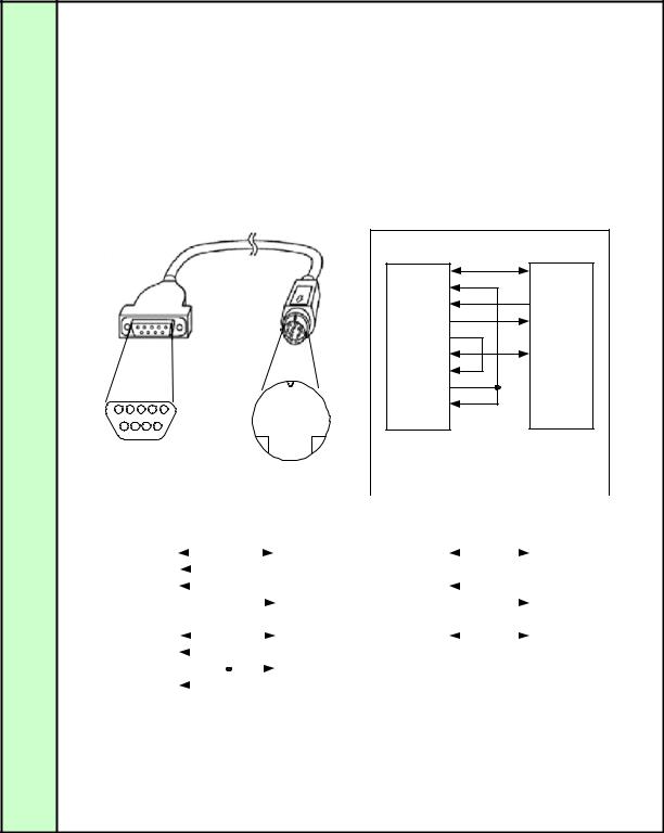
The connection diagram is |
||
|
|
|
|
|
Projector |
cable |
|
|
|
|
|
|
|
here. |
|
|
|
|
|
|
|
|
|
Send data SD |
SD Send data |
Receive data RD |
RD Receive data |
Signal ground SG |
SG Signal ground |
In the projector, none of the signal lines except for the three lines of SD, RD and SG are used!
If necessary, loop back its own signals at the PC side.
Control |
The projector has two control modes, the local mode and remote mode. |
||
Mode |
Most user commands are used in REMOTE mode. |
||
|
The two modes are set by the REMOTE and LOCAL commands. |
||
|
REMOTE command |
||
|
LOCAL mode |
REMOTE mode |
|
|
LOCAL command |
||
|
Initial mode of projector |
Except for RC and MAIN, all user commands are available in this mode. |
|
|
The available user commands are limited. |
None of the remote control and main unit panel buttons except for |
|
|
|
POWER can be used. |
|
|
|
Control is switched to this mode by the REMOTE command. |
|
|
|
|
|
Communication |
Communication between the PC and projector is performed by the projector responding bysending a response to the |
||
system |
|||
command sent from the PC. |
|
||
|
|
||
|
If AC power is supplied to the projector, communication is possible regardless of whether the power is on or off. |
||
PC |
Projector |
|
Commands |
|
Response |
PAGE 2

User Command Specifications |
2. Communication Specifications |
Commands
Transmission
format
Type
Null
Control
Setting
Reference
Request transmissions sent from PC to the projector
<Command character strings> <Delimiters>
<Command character |
Character strings consisting of 0 or more alphanumeric |
Reference |
Command List |
||||
strings> |
characters |
|
|
||||
|
|
|
|
|
|||
<Delimiters> |
One of CR (0Dh), LF (0Ah), CR+LF (0Dh+0Ah), Null (00h) |
|
|
|
|||
|
|
|
|
|
|
|
|
Type |
|
|
|
Description |
|
|
Response |
|
|
Commands with a command character string length of 0. No command |
|
■ OK |
|||
|
|
processing is performed. |
|
|
|||
|
|
|
|
|
|||
Null Commands |
|
|
|
|
|
|
□ BUSY |
|
<Null command character string>:= <Character string with length |
|
■ WARN |
||||
Character string |
|
|
|||||
|
0> |
|
|
|
|
■ ERR |
|
|
|
|
|
|
|
||
|
|
|
|
|
|
|
□ GET |
|
|
|
|
|
|
|
□ RANGE |
|
|
Projector control command. The format is shown below. |
|
|
■ OK |
||
Control command |
|
|
|
|
|
|
■ BUSY |
|
<Control command character string>:= <Control |
|
|
■ WARN |
|||
Character string |
|
□ |
<Parameter value> |
|
|
■ ERR |
|
|
|
name> |
|
|
□ GET |
||
|
|
|
|
|
|
|
|
|
|
|
|
|
|
|
□ RANGE |
|
|
Command that sets values for each parameter. The format is shown below. |
|
■ OK |
|||
Setting command |
|
|
|
|
|
|
■ BUSY |
|
<Setting command character strings>:= <Parameter |
|
|
■ WARN |
|||
Character string |
|
|
|
|
■ ERR |
||
|
|
name> |
= <Parameter value> |
|
|
|
|
|
|
For the definition of <Parameter value>, refer to "Parameter definitions." |
|
□ GET |
|||
|
|
|
|
|
|
|
□ RANGE |
|
|
Requests current value of each parameter. The format is shown below. |
|
□ OK |
|||
|
|
|
|
|
|
|
■ BUSY |
|
|
<Reference command character string>:=? <Parameter name> | |
|
■ WARN |
|||
|
|
GET□<Parameter name> |
|
|
■ ERR |
||
Reference |
|
|
|
|
|
|
■ GET |
|
|
|
|
|
|
□ RANGE |
|
command |
|
Requests range which can be set for each parameter. The format is shown |
|
□ OK |
|||
Character string |
|
below. |
|
|
|
|
|
|
|
|
|
|
|
|
■ BUSY |
|
|
<Range request command character string>:= |
|
|
■ WARN |
||
|
|
RANGE |
|
<Parameter name> |
|
|
■ ERR |
|
|
□ |
|
|
|
||
|
|
|
|
|
|
|
□ GET |
|
|
|
|
|
|
|
■ RANGE |
PAGE 3

User Command Specifications 2. Communication Specifications
Response |
Transmissions sent from Projector to PC in response to commands from PC |
|
|
|
||||||
Transmission |
<Response character string> <Delimiter> |
|
|
|
|
|||||
|
|
|
|
|
|
|
|
|
|
|
format |
|
|
|
|
|
|
|
|
|
|
|
|
|
|
|
|
|
|
|
||
|
|
<Response character |
|
Character strings consisting of one or more ASCII characters. |
|
|||||
|
|
string> |
|
The first two characters are always <one lowercase letter>: |
|
|
|
|||
|
|
|
|
|
The first character indicates the response type. |
|
|
|
||
|
|
|
|
|
|
|
|
|
|
|
|
|
|
|
|
|
Response type |
Meaning |
Example |
|
|
|
|
|
|
|
|
i |
State response |
i:OK i:BUSY etc. |
|
|
|
|
|
|
|
|
w |
Warning |
w:USER_COMMAND.. |
|
|
|
|
|
|
|
|
e |
Error |
e:000B INVALID.. |
|
|
|
|
|
|
|
|
g |
Reference command response |
g:AVOL=10 |
|
|
|
|
|
|
|
|
r |
Range request command response |
r:VKS=N, -50, 50 |
|
|
|
|
<Delimiters> |
|
Delimiters for commands sent from PC |
|
|
|
|||
Type |
|
|
|
|
|
|
|
|
|
|
|
Type |
|
|
|
|
Description |
|
|
|
|
OK |
|
OK |
After processing of each command is completed, a response is sent indicating that the next command |
|
||||||
|
|
response |
can be received. |
|
|
|
|
|||
|
|
|
<OK response character string>:=i:OK |
|
|
|
||||
BUSY |
|
|
|
|
||||||
|
BUSY |
This response is sent when a command cannot be received during processing. |
|
|||||||
|
|
response |
Wait for a few moments, and then try sending the command again. |
|
|
|
||||
|
|
|
<BUSY response character string>:=i:BUSY |
|
|
|
||||
|
|
|
Example: |
> IMAGE=2 |
|
|
|
|
||
|
|
|
|
< i:BUSY |
|
|
|
|
||
WARN |
|
|
|
|
||||||
|
WARN |
This response is sent when warning information is issued. Note that this command cannot be |
|
|||||||
|
|
response |
executed. |
|
|
|
|
|
|
|
|
|
|
<Warning response character string>:= w:<Warning description> |
|
|
|
||||
|
|
|
Example: |
> IMAGE=2 |
|
|
|
|
||
|
|
|
|
< w:USER_COMMAND_VERSION_IS_UPDATED |
|
|
|
|||
ERR |
|
|
|
|
|
|
|
|||
|
ERR |
An error message is output. |
|
|
|
|
||||
|
|
response |
|
|
|
|
|
|
|
|
<Error response character string>:= e:<Error code>□<Error message>
<Error code> is expressed as a four-digit hexadecimal number.
Refer to “Error List”!
|
|
Example: |
> abcdefg |
|
|
|
< e:0002 INVALID_COMMAND |
GET |
|
|
|
GET |
Request response for each parameter. |
||
|
response |
<GET response character string>:=g<Parameter name>=<Value> |
|
|
|
||
|
|
Example: |
> GET LANG or ? LANG |
|
|
|
< g:LANG=JPN |
RANGE |
|
|
|
RANGE |
This is the settable range response for each parameter. |
||
|
response |
|
|
|
|
<Range response character string> := r:<Parameter name>=<Type>, <Setting value range> |
|
<For <Setting value range> refer to the RANGE command.
Example: > RANGE CONT
< r:CONT=N, -20, 20
PAGE 4
User Command Specifications |
2. Communication Specifications |
Other |
Transmission is recognized when delimiter is received. |
|
Transmission |
||
recognition |
Even if a maximum transmission length is received, the entire received transmission will be lost unless a delimiter is received. |
|
|
||
Parameter |
The <Parameter value> is defined as shown below. |
|
value |
<Parameter value>:=<Value 1> <Value 2> .. <Value n> |
|
Definition |
||
|
<Value> := <Numerical value> | <ID> | “<Character string>” |
|
|
<Numerical value> |
:= [<Sign>] <Decimal character string (Min. 1 character to Max. 5 characters)> |
|
|
The range of valid values is -32768 to 32767. |
|
<ID> |
:= 1 or more ASCII characters (20h to 7Fh) |
|
<Character string> |
:= 0 or more ASCII characters (20h to 7Fh) |
|
|
|
Cable |
|
|
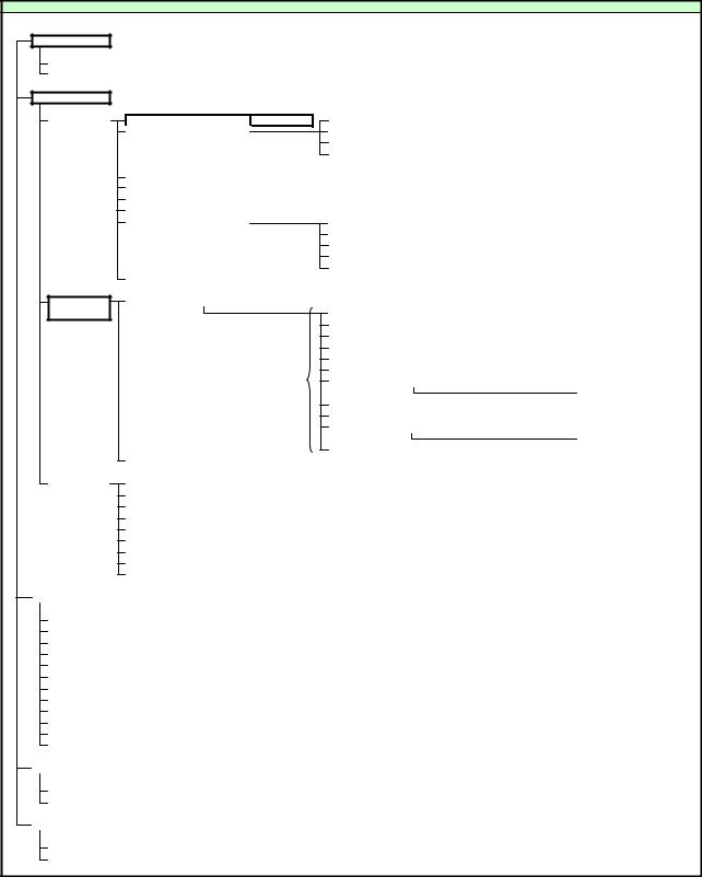
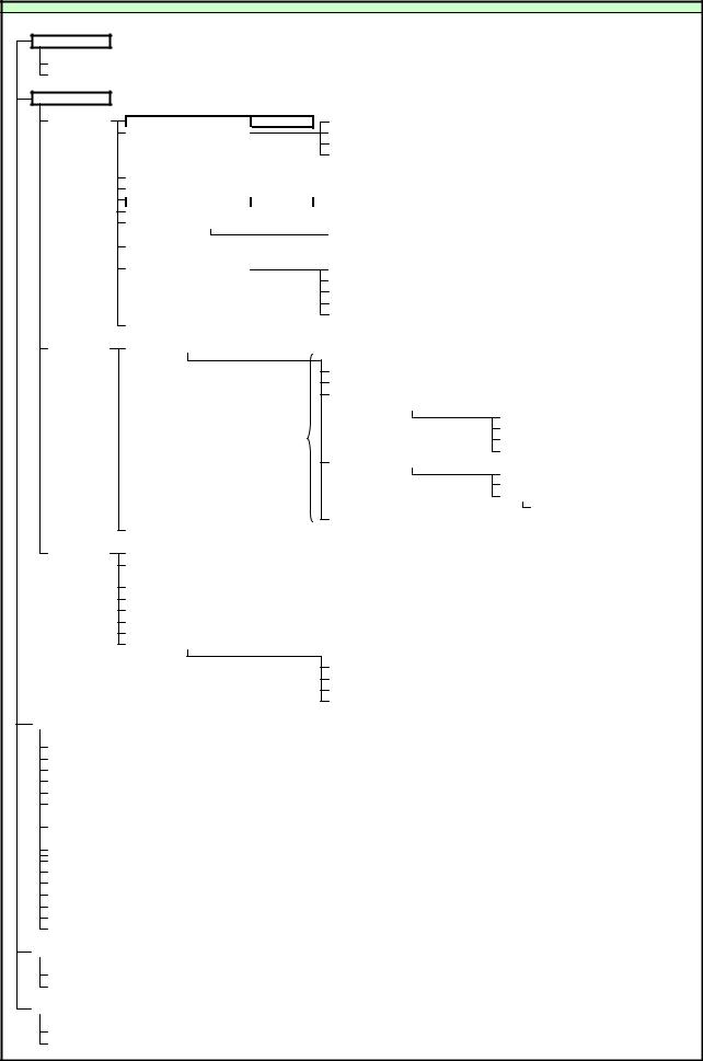
The connection diagram (example) for the cable connecting the PC and projector is shown below.
|
|
|
|
|
2 |
|
|
|
|
|
|
|
|
Sample 2 |
|
|
|
|
|
|
|
|
|
PC |
|
PJ |
|
|
|
|
|
SHIELD |
SHIELD |
||
|
|
|
|
|
1 |
CD (DCD) |
|
|
|
|
|
|
|
2 |
RD (RXD) |
3 |
SD (TXD) |
|
|
|
|
|
3 |
SD (TXD) |
5 |
RD (RXD) |
|
|
|
|
|
4 |
ER (DTR) |
|
|
|
|
|
|
|
5 |
SG (GND) |
4 |
SG (GND) |
|
|
|
|
|
6 |
DR (DSR) |
|
|
|
|
|
|
|
7 |
RS (RTS) |
|
|
|
|
|
|
8 |
CS (CTS) |
|
|
|
5 |
|
1 |
|
|
9 |
CI (RI) |
|
|
9 |
6 |
|
|
|
||||
|
|
|
|
|
|
|
||
|
|
|
|
|
|
|
|
|
|
|
|
|
|
|
|
|
|
|
|
|
|
|
|
|
|
|
|
|
|
|
|
|
|
Example of self-loopback connections when the |
|||||||||
|
|
|
|
PC |
|
|
|
|
|
|
PJ |
|
|
|
"CS" and "DR" pins are used in the connector of |
|||||||||||||||||||
|
|
|
|
|
|
|
|
|
|
|
|
|
PCthe PC.CS DR |
|||||||||||||||||||||
D-SUB 9pin FEMALE |
MINI DIN 8pin MALE |
|
|
|
||||||||||||||||||||||||||||||
|
|
|
|
|
|
|
|
|
|
|
|
|
||||||||||||||||||||||
|
|
|
|
|
|
|
|
|
|
|
|
|
|
|
|
|
|
|
|
|
|
|
|
|||||||||||
|
|
1 |
|
|
|
|
|
|
|
|
|
|
|
|
|
|
3 |
|
|
|
|
|
|
|||||||||||
|
|
Sample 1 |
|
|
|
|
|
|
|
|
PJ |
|
|
|
Sample 3 |
|
|
|
PJ |
|||||||||||||||
|
|
|
|
|
|
|
|
|
|
|
|
|
|
|
|
|
|
|
|
|
|
|
|
PC |
|
|
||||||||
|
|
|
|
PC |
|
|
|
|
|
|
|
|
|
|
|
|
|
|
||||||||||||||||
|
|
|
|
|
|
|
|
|
|
|
|
|
|
|
|
|
|
|
|
|
|
|
|
|
|
|
|
|
|
|||||
|
|
|
SHIELD |
|
|
|
|
|
|
|
|
|
|
|
|
|
|
SHIELD |
|
|
|
|
SHIELD |
|
|
|
SHIELD |
|
|
|||||
|
|
|
|
|
|
|
|
|
||||||||||||||||||||||||||
|
|
|
1 |
CD (DCD) |
|
|
|
|
|
|
|
|
|
|
|
3 |
SD (TXD) |
|
|
|
|
1 |
CD (DCD) |
|
|
3 |
SD (TXD) |
|
|
|||||
|
|
|
2 |
RD (RXD) |
|
|
|
|
|
|
|
|
|
|
|
|
|
|
2 |
RD (RXD) |
|
|
|
|
|
|||||||||
|
|
|
|
|
|
|
|
|
|
|||||||||||||||||||||||||
|
|
|
3 |
SD (TXD) |
|
|
|
|
|
|
|
|
|
|
5 |
RD (RXD) |
|
|
|
|
3 |
SD (TXD) |
|
|
5 |
RD (RXD) |
|
|
||||||
|
|
|
|
|
|
|
|
|||||||||||||||||||||||||||
|
|
|
4 |
ER (DTR) |
|
|
|
|
|
|
|
|
|
|
4 |
SG (GND) |
|
|
|
|
4 |
ER (DTR) |
|
|
4 |
SG (GND) |
|
|
||||||
|
|
|
5 |
SG (GND) |
|
|
|
|
|
|
|
|
|
|
|
|
|
5 |
SG (GND) |
|
|
|
|
|
||||||||||
|
|
|
|
|
|
|
||||||||||||||||||||||||||||
|
|
|
6 |
DR (DSR) |
|
|
|
|
|
|
|
|
|
|
|
2 |
NC |
|
|
|
|
6 |
DR (DSR) |
|
|
|
|
|
|
|||||
|
|
|
|
|
|
|
|
|
|
|
|
|
|
|||||||||||||||||||||
|
|
|
7 |
RS (RTS) |
|
|
|
|
|
|
|
|
|
|
|
|
|
|
|
7 |
RS (RTS) |
|
|
|
|
|
|
|||||||
|
|
|
|
|
|
|
|
|
|
|
|
|
|
|||||||||||||||||||||
|
|
|
8 |
CS (CTS) |
|
|
|
|
|
|
|
|
|
|
|
|
1 |
RS(RTS) |
|
|
|
|
8 |
CS (CTS) |
|
|
|
|
|
|
||||
|
|
|
|
|
|
|
|
|
|
|
|
|
|
|
||||||||||||||||||||
|
|
|
9 |
CI (RI) |
|
|
|
|
|
|
|
|
|
|
|
|
|
|
9 |
CI (RI) |
|
|
|
|
|
|
||||||||
|
|
|
|
|
|
|
|
|
|
|
|
|
|
|
|
|
6 |
NC |
|
|
|
|
|
|
|
|
|
|
|
|
|
|||
|
|
|
|
|
|
|
|
|
|
|
|
|
|
|
|
|
|
|
|
|
|
|
|
|
|
|
|
|
|
|||||
|
|
Canon's standard cable is used for |
|
|
7 |
NC |
|
|
|
|
|
|
|
|
|
|
|
|
|
|||||||||||||||
|
|
these connections. |
|
|
|
|
|
|
8 |
NC |
|
|
|
|
|
|
|
|
|
|
|
|
|
|||||||||||
|
|
|
|
|
|
|
|
|
|
|
|
|
|
|
|
|
|
|
||||||||||||||||
|
|
Do not use the "RS" pin in the |
|
|
|
|
|
|
|
|
|
|
Example of minimally required connections. |
|
||||||||||||||||||||
|
|
PCconnectorRS of the PC! |
|
|
|
|
|
|
|
|
|
|
|
|
||||||||||||||||||||
|
|
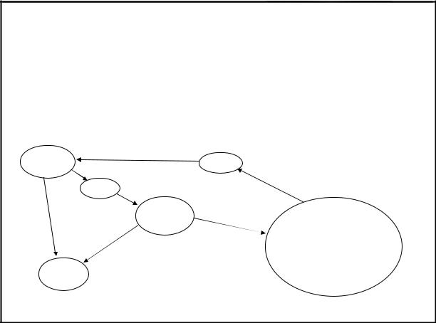
|
|
|
|
|
|
|
|
|
|
|
|
|
|
|
|
|||||||||||||||||
|
|
|
|
|
|
|
|
|
|
|
|
|
|
|
|
|
|
|
|
|
|
|
|
|
|
|
|
|
|
|
|
|
|
|
|
|
|
|
|
|
|
|
|
|
|
|
|
|
|
|
|
|
|
|
|
|
|
|
|
|
|
|
|
|
|
|
|
|
|
PAGE 5
User Command Specifications |
3. Communication Flow |
3. Communication Flow
Transmission |
At the sending side (PC), the transmission is sent within character intervals of Tc (character interval timeout). |
|
sent |
||
|
||
|
|
|
Transmission |
At the receiving side (Projector), data able to be received within the character interval of Tc is held, and receiving of a |
|
received |
delimiter is considered “transmission received”. |
|
|
||
|
If a received character interval exceeds Tc or a delimiter is not received within 256 characters, all data already received is |
|
|
lost, and the mode is reset to receive standby again. |
Command/ One response is always returned for each command sent from the PC.
Response (However, note that a response may not be returned when the internal receive buffer overflows due to reception of a large amount of data.)
PC |
Projector |
|
Commands |
Within Tr
Response
*The timeout interval between command and response (Tr) is 10 seconds.
Response If a response is not received within Tr (timeout interval between command and response) while in response reception reception standby after sending a command at the PC, resend the command in the “response reception timeout”.
timeout
PAGE 6
User Command Specifications 4. Command System SX50
4. Command System
SX50. User Command System
Mode change
Switch to Remote mode |
REMOTE |
Switch to Local mode |
LOCAL |
Setting/Control
Display setting |
|
Input select |
INPUT |
|
|
Input signal settings |
|
Total number of dots adjustment |
DOTS |
Tracking adjustment |
TRACK |
Horizontal/Vertical position adjustment |
HPOS/VPOS |
Horizontal/Vertical resolution adjustment |
HPIX/VPIX |
Image adjustment
Input signal selection |
SEL |
|
*User commands use only automatic selection of input signals. |
|
|
|
|
|
Screen settings |
ASPECT |
|
|
|
|
|
|
|
Auto PC |
AUTOPC |
|
*Running of Auto PC will change the values set in “Input signal settings”. |
|
||||
Menu display position setting |
|
|
|
|
|
|
|
|
User screen setting |
|
|
User screen registration |
|
|
|
|
|
|
|
|
User image position |
LOGOPOS |
|
|
|
|
|
|
|
Input when no signal |
NOSIG |
|
|
|
|
|
|
|
Screen when nothing shown |
NOSHOW |
|
|
|
|
|
|
|
Startup screen |
PJON |
|
|
|
|
Flip display |
IMAGEFLIP |
|
|
|
|
|
|
|
|
|
|
|
|
|
|
|
|
Image quality select |
IMAGE |
|
|
|
|
|
|
|
|
|
|
Brightness setting |
BRI |
|
|
|
|
|
|
|
Contrast setting |
CONT |
|
|
|
|
|
|
|
Sharpness setting |
SHARP |
|
|
|
|
|
|
|
Gamma correction |
GAMMA |
|
|
|
|
|
|
|
Dynamic gamma |
DGAMMA |
|
|
|
|
|
|
|
Progressive |
PROG |
|
|
|
|
*This is set for each input signal and image quality. |
|
Screen color correction |
WB |
|
|
|
|
|
|
|
|
|
|
|
RGB adjustment |
WBRGB |
|
|
|
|
Color saturation setting |
SAT |
|
|
|
|
|
|
|
Hue setting |
HUE |
|
|
|
|
|
|
|
Advanced color adjustment |
ACADJUST |
|
|
|
|
|
|
|
|
|
|
6-axis |
6 |
|
|
|
|
Lamp mode setting |
LAMP |
|
adjustment |
|
|
Image adjustment reset |
RESET |
RESET IMAGE |
|
|
|
|
|
|
|
System setting |
|
Terminal setting |
|
TERMINAL |
|
|
||
|
|
|
|
Power management |
|
PMM |
|
|
|
|
|
|
|
Electronic sound |
|
BVOL |
|
|
|
|
|
|
|
Key lock |
|
|
KEYLOCK |
|
|
|
|
|
|
Password registration |
|
|
|
|
|
|
|
|
|
Password setting |
|
|
|
|
|
|
|
|
|
Remote control setting |
|
RCCH |
|
|
|
|
|
|
|
Language setting |
|
LANG |
|
|
|
|
|
|
|
Reset |
|
|
RESET |
RESET SYSTEM |
|
|
|
|
|
|
|
|
|
|
|
Remote control/Key |
|
|
|
|
|
|
|||
|
|
|
|
|
|
|
|
|
|
|
Power supply |
|
POWER |
|
|
|
|
||
|
Input switching |
|
INPUT |
|
|
|
|
||
|
Keystone |
|
VKS/HKS |
|
|
|
|
||
|
Auto PC |
|
AUTOPC |
|
*Running of Auto PC will change the values set in “Input signal settings”. |
||||
|
Spotlight |
|
|
|
|
|
|
||
|
Volume adjustment |
|
AVOL |
|
|
|
|
||
|
Digital zoom |
|
|
|
|
|
|
||
|
Image quality select |
|
IMAGE |
|
*Same as “Setting/Control”-“Image Adjustment”-“Image Quality Select”. |
||||
|
Audio mute |
|
MUTE |
|
|
|
|
||
|
No show status setting |
|
|
|
|
|
|||
|
Freeze image |
|
|
|
|
|
|
||
|
Presentation timer setting |
|
|
|
|
|
|||
|
|
|
|
|
|
|
|
|
|
Emulate |
|
|
|
|
|
|
|
|
|
|
|
|
|
|
|
|
|
|
|
|
Remote control emulate |
RC |
|
|
|
|
|||
|
Key emulate |
|
MAIN |
|
|
|
|
||
|
|
|
|
|
|
|
|
||
Reference |
|
|
|
|
|
|
|
|
|
|
|
|
|
|
|
|
|
|
|
|
Retrieve each data |
|
GET |
|
|
|
|
||
|
Setting range request |
|
RANGE |
|
|
|
Indicates functions that are available in the menu but not available in the user commands. |
||
PAGE 7
User Command Specifications |
SX6 / SX60 / X600 |
SX6, SX60 or X600 User Command System
Mode change
Switch to Remote mode |
REMOTE |
Switch to Local mode |
LOCAL |
Setting/Control
Display setting |
|
Input select |
INPUT |
|
|
Input signal settings |
|
Total number of dots adjustment |
DOTS |
Tracking adjustment |
TRACK |
Horizontal/Vertical position adjustment |
HPOS/VPOS |
Horizontal/Vertical resolution adjustment |
HPIX/VPIX |
|
|
|
|
Input signal selection |
SEL |
|
*User commands use only automatic selection of input signals. |
|
|
|
|
||||||||
|
|
|
|
Screen settings |
ASPECT |
|
|
|
|
|
|
|
|
|
|
|
|
||
|
|
|
|
Auto PC |
|
AUTOPC |
|
*Running of Auto PC will change the values set in “Input signal settings”. |
|
|
|
||||||||
|
|
|
|
Menu display position setting |
|
|
|
|
|
|
|
|
|
|
|
|
|
||
|
|
|
|
Screen color correction |
WB |
|
|
|
|
|
|
|
|
|
|
|
|
||
|
|
|
|
|
|
|
|
|
RGB adjustment |
|
|
WBRGB |
|
|
|
|
|||
|
|
|
|
Progressive |
|
PROG |
|
|
|
|
|
|
|
|
|
|
|
|
|
|
|
|
|
|
|
|
|
|
|
|
|
|
|
|
|
|
|
|
|
|
|
|
|
User screen setting |
|
|
User screen registration |
|
|
|
|
|
|
|
|
|
|||
|
|
|
|
|
|
|
|
|
User image position |
|
|
LOGOPOS |
|
|
|
|
|||
|
|
|
|
|
|
|
|
|
Screen when no signal |
|
|
NOSIG |
|
|
|
|
|||
|
|
|
|
|
|
|
|
|
Screen when nothing shown |
NOSHOW |
|
|
|
|
|||||
|
|
|
|
|
|
|
|
|
Startup screen |
|
|
PJON |
|
|
|
|
|||
|
|
|
|
Flip display |
|
IMAGEFLIP |
|
|
|
|
|
|
|
|
|
|
|
|
|
|
|
|
|
|
|
|
|
|
|
|
|
|
|
|
|
|
|
|
|
|
Image |
|
Image quality select |
IMAGE |
|
|
|
|
|
|
|
|
|
|
|
|
|||
|
adjustment |
|
|
|
|
|
|
Brightness setting |
|
|
BRI |
|
|
|
|
||||
|
|
|
|
|
|
|
|
|
Contrast setting |
|
|
CONT |
|
|
|
|
|||
|
|
|
|
|
|
|
|
|
Sharpness setting |
|
|
SHARP |
|
|
|
|
|||
|
|
|
|
|
|
|
|
|
Gamma correction |
|
|
GAMMA |
|
|
|
|
|||
|
|
|
|
|
|
|
|
|
Color adjustment |
|
|
|
|
|
|
|
|
|
|
|
|
|
|
|
|
|
|
|
|
|
|
|
|
Color saturation setting |
SAT |
|
|||
|
|
|
|
|
|
|
|
|
|
|
|
|
|
Hue setting |
|
HUE |
|
||
|
|
|
|
*This is set for each input signal and image quality. |
|
|
|
|
|
|
Gain adjustment |
|
RGBGAIN |
|
|||||
|
|
|
|
|
|
|
|
|
|
|
|
|
|
Offset adjustment |
|
RGBOFFSET |
|
||
|
|
|
|
|
|
|
|
|
Advanced adjustment |
|
|
|
|
|
|
|
|
|
|
|
|
|
|
|
|
|
|
|
|
|
|
|
|
Dynamic gamma |
|
DGAMMA |
|
||
|
|
|
|
|
|
|
|
|
|
|
|
|
|
Memory color correction |
MEMCADJ |
|
|||
|
|
|
|
|
|
|
|
|
|
|
|
|
|
6-axis color adjustment |
6AXADJ |
|
|||
|
|
|
|
|
|
|
|
|
|
|
|
|
|
|
6-axis adjustment |
|
6 |
|
|
|
|
|
|
|
|
|
|
|
Lamp mode setting |
LAMP |
|
|
|
|
|
|
|
|
|
|
|
|
|
Image adjustment reset |
RESET |
RESET IMAGE |
|
|
|
|
|
|
|
|
|
||||
|
|
|
|
|
|
|
|
|
|
|
|
|
|
|
|
|
|
|
|
|
System setting |
|
Auto setup |
|
|
|
|
|
|
|
|
|
|
|
|
|
|
||
|
|
|
|
Power management mode |
PMM |
|
|
|
|
|
|
|
|
|
|
|
|
||
|
|
|
|
Direct power-on |
DPON |
|
|
|
|
|
|
|
|
|
|
|
|
||
|
|
|
|
Electronic sound |
BVOL |
|
|
|
|
|
|
|
|
|
|
|
|
||
|
|
|
|
Key lock |
|
KEYLOCK |
|
|
|
|
|
|
|
|
|
|
|
|
|
|
|
|
|
Language setting |
LANG |
|
|
|
|
|
|
|
|
|
|
|
|
||
|
|
|
|
Guide |
|
GUIDE |
|
|
|
|
|
|
|
|
|
|
|
|
|
|
|
|
|
LED illumination |
LEDILLUMINATE |
|
|
|
|
|
|
|
|
|
|
|
|
||
|
|
|
|
Other settings |
|
|
|
|
|
|
|
|
|
|
|
|
|
||
|
|
|
|
|
|
|
|
|
Remote control setting |
|
|
|
RCCH |
|
|
|
|
||
|
|
|
|
|
|
|
|
|
Password setting |
|
|
|
|
|
|
|
|
|
|
|
|
|
|
|
|
|
|
|
Password registration |
|
|
|
|
|
|
|
|
|
|
|
|
|
|
|
|
|
|
|
Lamp counter reset |
|
|
|
RESET |
RESET LAMPTIME |
|
||||
|
|
|
|
|
|
|
|
|
Factory settings |
|
|
|
RESET |
RESET SYSTEM |
|
||||
|
|
|
|
|
|
|
|
|
|
|
|
|
|
|
|
|
|
||
Remote control/Key |
|
|
|
|
|
|
|
|
|
|
|
|
|
|
|
|
|||
|
|
|
|
|
|
|
|
|
|
|
|
|
|
|
|
|
|
|
|
|
Power supply |
|
|
POWER |
|
|
|
|
|
|
|
|
|
|
|
|
|
||
|
Auto set |
|
|
AUTOSETEXE |
|
|
|
|
|
|
|
|
|
|
|
|
|
||
|
Image quality select |
|
|
IMAGE |
*Same as “Setting/Control”-“Image Adjustment”-“Image Quality Select”. |
|
|
|
|
||||||||||
|
Input switching |
|
|
INPUT |
|
|
|
|
|
|
|
|
|
|
|
|
|
||
|
Auto PC |
|
|
AUTOPC |
*Running of Auto PC will change the values set in “Input signal settings”. |
|
|
|
|
||||||||||
|
Focus |
|
|
FCONTDRV |
|
|
|
|
|
|
|
|
|
|
|
|
|
||
|
|
|
|
|
|
FSETPDRV |
|
|
|
|
|
|
|
|
|
|
|
|
|
|
Zoom |
|
|
ZCONTDRV |
|
|
|
|
|
|
|
|
|
|
|
|
|
||
|
|
|
|
|
|
ZSETPDRV |
|
|
|
|
|
|
|
|
|
|
|
|
|
|
Keystone |
|
|
VKS/HKS |
|
|
|
|
|
|
|
|
|
|
|
|
|
||
|
Digital zoom |
|
|
|
|
|
|
|
|
|
|
|
|
|
|
|
|
||
|
Spotlight |
|
|
|
|
|
|
|
|
|
|
|
|
|
|
|
|
||
|
No show status setting |
BLANK |
|
|
|
|
|
|
|
|
|
|
|
|
|
||||
|
Audio mute |
|
|
MUTE |
|
|
|
|
|
|
|
|
|
|
|
|
|
||
|
Volume adjustment |
|
|
AVOL |
|
|
|
|
|
|
|
|
|
|
|
|
|
||
|
Freeze image |
|
|
|
|
|
|
|
|
|
|
|
|
|
|
|
|
||
|
Presentation timer setting |
|
|
|
|
|
|
|
|
|
|
|
|
|
|
||||
|
|
|
|
|
|
|
|
|
|
|
|
|
|
|
|
|
|
||
Emulate |
|
|
|
|
|
|
|
|
|
|
|
|
|
|
|
|
|
|
|
|
|
|
|
|
|
|
|
|
|
|
|
|
|
|
|
|
|
|
|
|
Remote control emulate |
RC |
|
|
|
|
|
|
|
|
|
|
|
|
|
||||
|
Key emulate |
|
|
MAIN |
|
|
|
|
|
|
|
|
|
|
|
|
|
||
|
|
|
|
|
|
|
|
|
|
|
|
|
|
|
|
|
|||
Reference |
|
|
|
|
|
|
|
|
|
|
|
|
|
|
|
|
|
|
|
|
|
|
|
|
|
|
|
|
|
|
|
|
|
|
|
|
|
|
|
|
Retrieve each data |
|
|
GET |
|
|
|
|
|
|
|
|
|
|
|
|
|
||
|
Setting range request |
|
|
RANGE |
|
|
|
Indicates functions that are available in the menu but not available in the user commands. |
|
||||||||||
PAGE 8
User Command Specifications |
5. Control Mode |
5. Control Mode
The table below shows the states and limitations of the LOCAL and REMOTE control modes.
|
Mode |
|
|
LOCAL mode |
|
|
|
|
|
REMOTE mode |
||
Item |
|
|
|
|
|
|
|
|
||||
|
|
|
|
|
|
|
|
|
|
|
||
|
|
Mode where projector control/operation is |
Mode where projector control/operation is |
|||||||||
Description |
performed by the main unit or remote control. |
performed by a PC or other external device. |
||||||||||
Initial mode when microcomputer is started. |
(The PC or other external device is connected by |
|||||||||||
|
|
|||||||||||
|
|
|
|
|
|
|
a serial cable.) |
|||||
LED |
Status |
State indicator |
|
|
Constant remote indicator 2 |
|||||||
ALM |
ALM state indicator |
|
|
ALM state indicator |
||||||||
|
|
|
||||||||||
|
|
AC power supply to projector |
|
|
REMOTE command |
|||||||
Transition method |
Manual power on/off |
|
|
|
|
|
|
|
||||
LOCAL command |
|
|
|
|
|
|
|
|||||
|
|
|
|
|
|
|
|
|
||||
|
|
Power management standby/exit mode transfe |
|
|
|
|
|
|||||
|
Main unit keys |
All available |
|
|
Only POWER button is available |
|||||||
Operation |
Remote control |
All available |
|
|
Only POWER button is available |
|||||||
buttons |
keys |
|
|
|
|
|
|
|
|
|
|
|
|
Emulation |
Available |
1 |
|
|
Not available |
|
|
||||
|
|
5 minutes elapsed from no signal |
|
|
Operation is as follows depending on the model. |
|||||||
|
|
|
|
|
|
|
|
|
|
|
|
|
|
|
|
|
|
|
|
|
Model |
|
Operation |
|
|
|
|
|
|
|
|
|
|
SX50 |
|
No switching to standby or exit |
|
|
|
|
|
|
|
|
|
|
|
mode. |
|
||
Power |
Switching |
|
|
|
|
|
|
|
|
|
||
|
|
|
|
|
|
SX6 |
|
5 minutes elapsed from no |
|
|||
management |
|
|
|
|
|
|
|
|
|
|||
|
|
|
|
|
|
|
|
signal |
|
|||
standby and exit |
|
|
|
|
|
|
|
SX60 |
|
|
||
modes |
|
|
|
|
|
|
|
|
Control is switched to "local |
|
||
|
|
|
|
|
|
|
|
X600 |
|
mode" after mode switching. |
|
|
3 |
|
|
|
|
|
|
|
|
|
|
||
|
|
|
|
|
|
|
|
|
|
|
||
|
|
|
|
|
|
|
|
|
||||
|
|
Signal input |
|
|
REMOTE command |
|||||||
|
Return |
Remote control button pressed |
|
|
|
|
|
|
|
|||
|
Main unit button pressed |
|
|
|
|
|
|
|
||||
|
|
|
|
|
|
|
|
|
||||
|
|
Emulation |
|
|
|
|
|
|
|
|
||
|
|
|
For the SX50 |
|
|
|
All commands except for "RC" and "MAIN" |
|||||
|
|
|
Command/parameter |
Remarks |
|
|
|
|
|
|
||
|
|
|
REMOTE |
|
|
|
|
|
|
|
||
|
|
|
LOCAL |
|
|
|
|
|
|
|
|
|
|
|
|
GET |
MODE |
|
|
|
|
|
|
|
|
|
|
|
MAIN |
|
|
|
|
|
|
|
|
|
|
|
|
RC |
|
|
|
|
|
|
|
|
|
|
|
|
For the SX6, SX60 or X600 |
|
|
|
|
|
|
|
||
|
|
|
Command/parameter |
Remarks |
|
|
|
|
|
|
||
|
|
|
GET |
COMVER |
|
|
|
|
|
|
|
|
|
|
|
GET |
ERROR |
|
|
|
|
|
|
|
|
Commands supported |
|
GET |
FREEZE |
|
|
|
|
|
|
|
||
|
GET |
INPUT |
|
|
|
|
|
|
|
|||
|
|
|
|
|
|
|
|
|
|
|||
|
|
|
GET |
LAMPCOUNTER |
|
|
|
|
|
|
|
|
|
|
|
GET |
MODE |
|
|
|
|
|
|
|
|
|
|
|
GET |
MUTE |
|
|
|
|
|
|
|
|
|
|
|
GET |
NOSHOWSTATUS |
|
|
|
|
|
|
|
|
|
|
|
GET |
POWER |
|
|
|
|
|
|
|
|
|
|
|
GET |
PRODCODE |
|
|
|
|
|
|
|
|
|
|
|
GET |
ROMVER |
|
|
|
|
|
|
|
|
|
|
|
GET |
SIGNALSTATUS |
|
|
|
|
|
|
|
|
|
|
|
LOCAL |
|
|
|
|
|
|
|
|
|
|
|
|
MAIN |
|
|
|
|
|
|
|
|
|
|
|
|
RC |
|
|
|
|
|
|
|
|
|
|
|
|
REMOTE |
|
|
|
|
|
|
|
||
|
|
|
||||||||||
Special mode |
Executable with remote control or main unit buttons |
Not executable in any state |
||||||||||
(Service mode) |
|
|
|
|
|
|
|
|
|
|
||
*1 However, switching to the USB mouse function or Special mode is not allowed.
*2 If the control mode is REMOTE, the following are displayed regardless of whether the power is on or off. *3 When the power management setting is "standby" or "exit"
LED indicator pattern during REMOTE mode
■■
PAGE 9

User Command Specifications |
6. Key/Emulation function |
16. Key/Emulation function
6. Key/Emulation function
The table below shows how the main unit/remote control keys and emulation function operate in each control mode
Key/Emulation |
|
LOCAL mode |
|
|
REMOTE mode |
|
|
Unlock |
Remote |
|
Main unit |
Unlock |
Remote control |
Main unit key |
|
|
control lock |
|
key lock |
lock |
lock |
||
|
|
|
|
||||
Remote control |
○ |
× |
|
○ |
POWER only |
× |
POWER only |
|
|
|
|
|
|
|
|
Main unit keys |
○ |
○ |
|
× |
POWER only |
POWER only |
× |
|
|
|
|
|
|
|
|
Remote control emulation |
○ |
○ |
|
○ |
× |
× |
× |
|
|
|
|
|
|
|
|
Main unit key emulation |
○ |
○ |
|
○ |
× |
× |
× |
|
|
|
|
|
|
|
|
PAGE 10
User Command Specifications |
7. Power Management Mode |
e
7. Power Management Mode
Concerning the processing for switching to the power management standby or exit mode in the remote or local mode
Mode |
SX50 |
SX6/SX60/SX600 |
Remote |
The power management standby or exit mode is |
The power management standby or exit mode is |
|
not established. |
established when no signals are supplied for at least 5 |
|
(No countdown is initiated.) |
The countdown is aborted by any command other than |
|
|
GET/RANGE. |
|
|
Control is switched to the "local mode" in the standby or |
|
|
exit mode. |
Local |
The power management standby or exit mode is |
established when no signals are supplied for at least 5 |
|
minutes. |
|
Projecting in
progress
Lamp off
Events for returning from standby mode
Signal input
Pressing of a button on main unit or remote contro Lamp on REMOTE command
RC/MAIN command (excluding RC/MAIN*-REP
Lamp |
When the standby |
cooling in |
mode is established |
progress |
Power management activated |
When the exit mode is established |
Processing only for commands |
|
enabled in power management |
||
|
||
|
standby mode |
Power Off
PAGE 11
User Command Specifications |
8. Command List |
8. Command List
Item |
Commands |
|
Description |
|
Command type |
||
|
Mode |
Control |
Setting |
Reference |
|||
|
|
|
|
||||
1 |
REMOTE |
Switching to Remote mode |
○ |
|
|
|
|
2 |
LOCAL |
Switching to Local mode |
○ |
|
|
|
|
3 |
POWER |
Power supply control |
|
○ |
|
|
|
4 |
AUTOSETEXE |
Auto setup execution |
|
○ |
|
|
|
5 |
BLANK |
BLANK function |
|
|
○ |
|
|
6 |
INPUT |
Input terminal select |
|
|
○ |
|
|
7 |
AUTOPC |
Auto PC execution |
|
○ |
|
|
|
8 |
DOTS |
|
Total number of dots adjustment |
|
|
○ |
|
9 |
TRACK |
Input |
Tracking adjustment |
|
|
○ |
|
10 |
HPOS |
Horizontal position adjustment |
|
|
○ |
|
|
|
|
signal |
|
|
|
|
|
11 |
VPOS |
Vertical position adjustment |
|
|
○ |
|
|
settings |
|
|
|
||||
12 |
HPIX |
Horizontal resolution adjustment |
|
|
○ |
|
|
|
|
|
|
||||
13 |
VPIX |
|
Vertical resolution adjustment |
|
|
○ |
|
14 |
SEL |
Input signal selection |
|
|
○ |
|
|
15 |
ASPECT |
Screen settings |
|
|
○ |
|
|
16 |
IMAGE |
Image mode |
|
|
○ |
|
|
17 |
BRI |
Brightness setting |
|
|
○ |
|
|
18 |
CONT |
Contrast setting |
|
|
○ |
|
|
19 |
SHARP |
Sharpness setting |
|
|
○ |
|
|
20 |
GAMMA |
Gamma correction |
|
|
○ |
|
|
21 |
DGAMMA |
Dynamic gamma |
|
|
○ |
|
|
22 |
PROG |
Progressive |
|
|
○ |
|
|
23 |
WB |
Screen color correction |
|
|
○ |
|
|
24 |
WBRGB |
Screen color correction (RGB adjustment) |
|
|
○ |
|
|
25 |
SAT |
Color saturation setting |
|
|
○ |
|
|
26 |
HUE |
Hue setting |
|
|
○ |
|
|
27 |
RGBGAIN |
RGB gain adjustment |
|
|
○ |
|
|
28 |
RGBOFFSET |
RGB offset adjustment |
|
|
○ |
|
|
29 |
ACADJUST |
Advanced color adjustment |
|
|
○ |
|
|
30 |
ACADJUST |
Memory color correction |
|
|
○ |
|
|
31 |
6AXADJ |
6-axis adjustment ON/OFF |
|
|
○ |
|
|
32 |
6AXR |
|
R setting |
|
|
○ |
|
33 |
6AXG |
6-axis |
G setting |
|
|
○ |
|
34 |
6AXB |
B setting |
|
|
○ |
|
|
|
|
color |
|
|
|
|
|
35 |
6AXC |
C setting |
|
|
○ |
|
|
adjust |
|
|
|
||||
36 |
6AXM |
M setting |
|
|
○ |
|
|
|
|
|
|
||||
37 |
6AXY |
|
Y setting |
|
|
○ |
|
38 |
LAMP |
Lamp |
mode setting |
|
|
○ |
|
39 |
RESET |
Reset |
|
|
○ |
|
|
40 |
VKS |
Trapezoid adjustment (vertical keystone) |
|
|
○ |
|
|
41 |
HKS |
Trapezoid adjustment (horizontal keystone) |
|
|
○ |
|
|
42 |
AVOL |
Volume adjustment |
|
|
○ |
|
|
43 |
MUTE |
Mute |
|
|
|
○ |
|
44 |
BVOL |
Beep sound setting |
|
|
○ |
|
|
45 |
IMAGEFLIP |
Flip display control |
|
|
○ |
|
|
46 |
PMM |
Power management |
|
|
○ |
|
|
47 |
PJON |
Display screen at startup setting |
|
|
○ |
|
|
48 |
NOSIG |
Display screen when no signal setting |
|
|
○ |
|
|
49 |
NOSHOW |
Display screen setting when nothing shown |
|
|
○ |
|
|
50 |
LOGOPOS |
User image position setting |
|
|
○ |
|
|
51 |
LANG |
Language selection |
|
|
○ |
|
|
52 |
TERMINAL |
Terminal setting |
|
|
○ |
|
|
53 |
KEYLOCK |
Key lock setting |
|
|
○ |
|
|
54 |
RCCH |
Remote control setting |
|
|
○ |
|
|
55 |
GUIDE |
Guide setting |
|
|
○ |
|
|
56 |
DPON |
Direct power-on setting |
|
|
○ |
|
|
57 |
LEDILLUMINATE |
Emotional LED and signal sensing LED lighting control |
|
|
○ |
|
|
58 |
ZSTEPDRV |
Zoom lens step drive control |
|
|
○ |
|
|
59 |
ZCONTDRV |
Zoom lens continuous drive control |
|
|
○ |
|
|
60 |
FSTEPDRV |
Focus lens step drive control |
|
|
○ |
|
|
61 |
FCONTDRV |
Focus lens continuous drive control |
|
|
○ |
|
|
62 |
RC |
Remote control operation emulation |
|
○ |
|
|
|
63 |
MAIN |
Front panel button operation emulation |
|
○ |
|
|
|
64 |
GET |
Retrieve data |
|
|
|
○ |
|
65 |
RANGE |
Setting range request |
|
|
|
○ |
|
PAGE 12
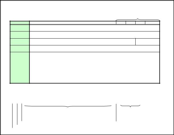
User Command Specifications |
9. Details of command |
9. Details of command
Descriptions of each command are provided starting from the next page.
The command descriptions have the format shown below.
Command type
Commands * Alphabetic command name Mode Control Setting Reference
Function * This briefly describes the command function.
Format * This indicates the command format.
Parameter * This explains the required parameters for the command. |
Parameter types |
Response * This describes the command response.
Description * This includes the command function, conditions, and notes.
Example * This provides command usage examples. |
|
|
|
|
|||||
|
|
|
|
|
|
|
|
|
|
Commands |
SX50 |
SX6 |
SX60 |
X600 |
|
|
|
|
|
supported |
01.**** |
11.**** |
11.**** |
11.**** |
|
|
|
|
|
|
|
○ |
○ |
○ |
○ |
|
|
|
|
*Indicated here are the commands supported by each model (and user command version). "O": supported; "x": not supported.
Supported Command States * This defines the environments that support the command (power supply state, input signal state, control mode).
Model |
|
Power |
|
|
|
|
Input |
|
|
|
|
Mode |
Remarks |
||||
|
|
OFF |
ON |
PM |
D-RGB |
A-RGB1 |
A-RGB2 |
Comp |
Video |
S-Video |
D-Video |
SCART |
None |
Remote |
Local |
|
|
× |
○ |
× |
|
× |
× |
× |
○ |
○ |
○ |
× |
○ |
× |
× |
○ |
× |
|
|
The command is enabled in states marked by “○”.
The command is enabled in control modes marked by “○”.
“○” when the power supply state is enabled while power management is in standby. Input signal is required when “×”. “○” when power supply state is ON.
“○” when power supply state is OFF.
PAGE 13
User Command Specifications |
(SET command) |
PAGE 13
User Command Specifications |
(GET command) |
PAGE 13
User Command Specifications |
(RANGE command) |
PAGE 13
User Command Specifications |
9. Details of command REMOTE |
1
Commands |
REMOTE |
|
|
|
|
|
|
|
|
|
|
|
|
Mode |
Control |
Setting |
Reference |
||||||||
Function |
Switch to Remote mode |
|
|
|
|
|
|
|
|
|
|
|
|
|
|
|
|
|
|||||||
|
|
|
|
|
|
|
|
|
|
|
|
|
|
|
|
|
|
|
|
|
|
|
|
|
|
|
Format |
|
REMOTE |
|
|
|
|
|
|
|
|
|
|
|
|
|
|
|
|
|
|
|
|
||
|
|
|
|
|
|
|
|
|
|
|
|
|
|
|
|
|
|
|
|
|
|
|
|
|
|
Parameter |
None |
|
|
|
|
|
|
|
|
|
|
|
|
|
|
|
|
|
|
|
|
||||
|
|
|
|
|
|
|
|
|
|
|
|
|
|
|
|
|
|
|
|
|
|||||
Response |
"i:OK" is returned when it was possible to switch the mode properly. |
|
|
|
|
|
|
||||||||||||||||||
|
|
|
For all other responses, refer to "Error List." |
|
|
|
|
|
|
|
|
|
|
|
|
||||||||||
|
|
|
|
|
|
|
|
|
|
|
|
|
|
|
|
|
|
|
|
|
|
|
|
||
Description |
This switches to Remote mode. |
|
|
|
|
|
|
|
|
|
|
|
|
|
|
||||||||||
|
|
|
-1 |
During Remote mode, all buttons are disabled except for the front panel and remote control |
|||||||||||||||||||||
|
|
|
-2 |
POWER button. |
|
|
|
|
|
|
|
|
|
|
|
|
|
|
|
|
|
|
|||
|
|
|
This command can be used in any projector mode. |
|
|
|
|
|
|
|
|
||||||||||||||
|
|
|
|
However, zoom or focus lens drive stops if the zoom or focus lens is being driven. |
|
||||||||||||||||||||
|
|
|
-3 |
(Refer to the ZCONTDRV command and FCONTDRV command.) |
|
|
|
|
|||||||||||||||||
|
|
|
If, in the power management standby status, the "REMOTE" command was received and |
|
|||||||||||||||||||||
|
|
|
|
operation was switched to the remote mode, the "power-on" (lamp lighted) status is established |
|||||||||||||||||||||
|
|
|
-4 |
unconditionally. |
|
|
|
|
|
|
|
|
|
|
|
|
|
|
|
|
|
|
|||
|
|
|
With the SX50, the setting, control and reference commands except for RC and MAIN can be |
||||||||||||||||||||||
|
|
|
|
used only in the remote mode. |
|
|
|
|
|
|
|
|
|
|
|
|
|
|
|||||||
|
|
|
|
(RC and MAIN can be used only in the "local mode.") |
|
|
|
|
|
|
|
|
|||||||||||||
|
|
|
|
With the SX6, SX60 and X600, there are several setting, control and reference commands |
|||||||||||||||||||||
|
|
|
|
which can be used in the local mode. |
|
|
|
|
|
|
|
|
|
|
|
|
|||||||||
|
|
|
|
(Refer to the LOCAL command.) |
|
|
|
|
|
|
|
|
|
|
|
|
|
|
|||||||
|
|
|
-5 |
When this command is executed, all the statuses and settings listed below are cleared. |
|
||||||||||||||||||||
|
|
|
|
Digital zoom |
|
|
|
|
|
|
|
|
|
|
|
|
|
|
|
|
|
|
|||
|
|
|
|
Presentation timer display |
|
|
|
|
|
|
|
|
|
|
|
|
|
|
|||||||
|
|
|
|
Spotlight display |
|
|
|
|
|
|
|
|
|
|
|
|
|
|
|
|
|
||||
|
|
|
|
Screen temporary off (NoShow) |
|
|
|
|
|
|
|
|
|
|
|
|
|||||||||
|
|
|
|
Freeze image (Freeze) |
|
|
|
|
|
|
|
|
|
|
|
|
|
|
|||||||
|
|
|
|
Command now being executed (except during "user image registration" |
|
|
|
||||||||||||||||||
|
|
|
-6 |
Focusing, zooming underway (with the SX6, SX60 and X600 |
|
|
|
|
|||||||||||||||||
|
|
|
"Guide display" is not cleared by the transfer of operation to the remote mode. If necessary, |
||||||||||||||||||||||
|
|
|
-7 |
clear the display using the GUIDE command. |
|
|
|
|
|
|
|
|
|
|
|||||||||||
|
|
|
The current mode can be referenced using the applicable GET command. |
|
|
|
|||||||||||||||||||
|
|
|
|
|
|
|
|
|
|
|
|
|
|
|
|
|
|
|
|
|
|
|
|
|
|
Example |
Mode switching |
|
|
|
|
|
|
|
|
|
|
|
|
|
|
|
|
|
|
||||||
|
|
|
> REMOTE |
|
|
|
|
|
|
|
|
|
|
|
|
|
|
|
|
|
|
|
|
||
|
|
|
< i:OK |
|
|
|
|
|
|
|
|
|
|
|
|
|
|
|
|
|
|
|
|
||
|
|
|
Mode viewing |
|
|
|
|
|
|
|
|
|
|
|
|
|
|
|
|
|
|
|
|
||
|
|
|
> GET MODE or |
|
|
|
|
|
|
|
|
|
|
|
|
|
|
|
|
|
|
||||
|
|
|
< g:MODE=LOCAL |
|
|
|
|
|
|
|
|
|
|
|
|
|
|
|
|
|
|
||||
|
|
|
* Commands are indicated by ">", and responses are indicated by "<". |
|
|
|
|
|
|
|
|
||||||||||||||
Commands |
|
SX50 |
|
SX6 |
|
SX60 |
|
X600 |
|
|
|
|
|
|
|
|
|
|
|
|
|||||
supported |
01.00** |
|
01.01** |
|
01.01** |
|
01.01** |
|
|
|
|
|
|
|
|
|
|
|
|||||||
|
|
|
|
○ |
|
○ |
|
|
○ |
|
○ |
|
|
|
|
|
|
|
|
|
|
|
|
||
|
|
|
|
|
|
|
|
|
|
|
|
|
|
|
|
|
|
|
|
|
|
|
|
|
|
Supported Command States |
|
|
|
|
|
|
|
|
|
|
|
|
|
|
|
|
|
|
|
|
|||||
Model |
Power |
|
|
|
|
|
|
|
|
Input |
|
|
|
|
|
|
|
|
Mode |
|
Remarks |
||||
|
OFF |
ON |
PM |
D-RGB |
A-RGB1 |
A-RGB2 |
Comp |
|
Video |
|
S-Video |
D-Video |
SCART |
|
None |
Remote |
Local |
|
|
||||||
SX50 |
○ |
○ |
○ |
○ |
|
○ |
|
○ |
|
○ |
|
○ |
|
○ |
– |
|
– |
|
○ |
○ |
○ |
|
|
||
SX6 |
○ |
○ |
○ |
○ |
|
○ |
|
○ |
|
○ |
|
○ |
|
○ |
○ |
|
○ |
|
○ |
○ |
○ |
|
|
||
SX60 |
|
|
|
|
|
|
|
|
|
|
|
|
|
|
|
|
|
|
|
|
|
|
|
|
|
X600 |
|
|
|
|
|
|
|
|
|
|
|
|
|
|
|
|
|
|
|
|
|
|
|
|
|
PAGE 14
User Command Specifications |
9. Details of command LOCAL |
1
Commands |
LOCAL |
|
|
|
|
|
|
|
|
|
|
|
|
|
|
|
|
|
Mode |
Control |
Setting |
Reference |
||||||
Function |
Switch to Local mode |
|
|
|
|
|
|
|
|
|
|
|
|
|
|
|
|
|
|
|
|
|||||||
|
|
|
|
|
|
|
|
|
|
|
|
|
|
|
|
|
|
|
|
|
|
|
|
|
|
|
|
|
|
Format |
|
LOCAL |
|
|
|
|
|
|
|
|
|
|
|
|
|
|
|
|
|
|
|
|
|
|
|||
|
|
|
|
|
|
|
|
|
|
|
|
|
|
|
|
|
|
|
|
|
|
|
|
|
|
|
|
|
Parameter |
None |
|
|
|
|
|
|
|
|
|
|
|
|
|
|
|
|
|
|
|
|
|
|
|||||
|
|
|
|
|
|
|
|
|
|
|
|
|
|
|
|
|
|
|
|
|
|
|
||||||
Response |
"i:OK" is returned when it was possible to switch the mode properly. |
|
|
|
||||||||||||||||||||||||
|
|
|
For all other responses, refer to "Error List." |
|
|
|
|
|
|
|
|
|
|
|
|
|
|
|||||||||||
|
|
|
|
|
|
|
|
|
|
|
|
|
|
|
|
|
|
|
|
|
|
|
|
|
|
|
||
Description |
This switches to Local mode. |
|
|
|
|
|
|
|
|
|
|
|
|
|
|
|
|
|
||||||||||
|
|
|
-1 The following commands can be used while the local mode is established. |
|
|
|||||||||||||||||||||||
|
|
|
|
|
|
|
|
|
|
|
|
|
|
|
|
|
|
|
|
|
|
|
|
|
||||
|
|
|
|
|
|
Command/parameter |
|
|
Errors supported by model |
|
|
|
|
|||||||||||||||
|
|
|
|
|
|
|
SX50 |
|
SX6 |
|
SX60 |
|
|
X600 |
|
|
|
|
||||||||||
|
|
|
|
|
|
|
|
|
|
|
|
|
01.00** |
01.01** |
01.01** |
|
01.01** |
|
|
|
|
|||||||
|
|
|
|
|
REMOTE |
|
|
|
|
|
○ |
|
○ |
|
○ |
|
|
○ |
|
|
|
|
||||||
|
|
|
|
|
LOCAL |
|
|
|
|
|
○ |
|
○ |
|
○ |
|
|
○ |
|
|
|
|
||||||
|
|
|
|
|
GET MODE |
|
|
|
|
|
○ |
|
○ |
|
○ |
|
|
○ |
|
|
|
|
||||||
|
|
|
|
|
GET COMVER |
|
|
|
|
× |
|
○ |
|
○ |
|
|
○ |
|
|
|
|
|||||||
|
|
|
|
|
GET ERR |
|
|
|
|
|
× |
|
○ |
|
○ |
|
|
○ |
|
|
|
|
||||||
|
|
|
|
|
GET FREEZE |
|
|
|
|
|
× |
|
○ |
|
○ |
|
|
○ |
|
|
|
|
||||||
|
|
|
|
|
GET INPUT |
|
|
|
|
|
× |
|
○ |
|
○ |
|
|
○ |
|
|
|
|
||||||
|
|
|
|
|
GET LAMPCOUNTER |
|
|
× |
|
○ |
|
○ |
|
|
○ |
|
|
|
|
|||||||||
|
|
|
|
|
GET MUTE |
|
|
|
|
|
× |
|
○ |
|
○ |
|
|
○ |
|
|
|
|
||||||
|
|
|
|
|
GET NOSHOWSTATUS |
|
|
× |
|
○ |
|
○ |
|
|
○ |
|
|
|
|
|||||||||
|
|
|
|
|
GET POWER |
|
|
|
|
|
× |
|
○ |
|
○ |
|
|
○ |
|
|
|
|
||||||
|
|
|
|
|
GET PRODCODE |
|
|
|
|
× |
|
○ |
|
○ |
|
|
○ |
|
|
|
|
|||||||
|
|
|
|
|
GET ROMVER |
|
|
|
|
× |
|
○ |
|
○ |
|
|
○ |
|
|
|
|
|||||||
|
|
|
|
|
GET SIGNALSTATUS |
|
|
× |
|
○ |
|
○ |
|
|
○ |
|
|
|
|
|||||||||
|
|
|
|
|
MAIN |
|
|
|
|
|
|
|
○ |
|
○ |
|
○ |
|
|
○ |
|
|
|
|
||||
|
|
|
|
|
RC |
|
|
|
|
|
|
|
○ |
|
○ |
|
○ |
|
|
○ |
|
|
|
|
||||
|
|
|
-2 This command can be used in any projector mode. |
|
|
|
|
|
|
|
|
|
|
|
||||||||||||||
|
|
|
|
However, zoom or focus lens drive stops if the zoom or focus lens is being driven. |
|
|||||||||||||||||||||||
|
|
|
|
(Refer to the ZCONTDRV command and FCONTDRV command.) |
|
|
|
|||||||||||||||||||||
|
|
|
-3 The current mode can be referenced using the applicable GET command. |
|
|
|||||||||||||||||||||||
|
|
|
-4 The "BLANK status" is cleared. Refer to BLANK command. |
|
|
|
|
|
|
|
||||||||||||||||||
|
|
|
|
|
|
|
|
|
|
|
|
|
|
|
|
|
|
|
|
|
|
|
|
|
|
|
||
Example |
Mode switching |
|
|
|
|
|
|
|
|
|
|
|
|
|
|
|
|
|
|
|
|
|||||||
|
|
|
> LOCAL |
|
|
|
|
|
|
|
|
|
|
|
|
|
|
|
|
|
|
|
|
|
|
|||
|
|
|
< i:OK |
|
|
|
|
|
|
|
|
|
|
|
|
|
|
|
|
|
|
|
|
|
|
|||
|
|
|
Mode viewing |
|
|
|
|
|
|
|
|
|
|
|
|
|
|
|
|
|
|
|
|
|||||
|
|
|
> GET MODE or ?MODE |
|
|
|
|
|
|
|
|
|
|
|
|
|
|
|
|
|
||||||||
|
|
|
< g:MODE=LOCAL |
|
|
|
|
|
|
|
|
|
|
|
|
|
|
|
|
|
|
|
|
|||||
|
|
|
* Commands are indicated by ">", and responses are indicated by "<". |
|
|
|
|
|
|
|
||||||||||||||||||
Commands |
|
SX50 |
|
SX6 |
|
SX60 |
X600 |
|
|
|
|
|
|
|
|
|
|
|
|
|
|
|||||||
supported |
01.00** |
|
01.01** |
|
01.01** |
01.01** |
|
|
|
|
|
|
|
|
|
|
|
|
|
|
||||||||
|
|
|
|
○ |
|
○ |
|
|
○ |
|
○ |
|
|
|
|
|
|
|
|
|
|
|
|
|
|
|||
|
|
|
|
|
|
|
|
|
|
|
|
|
|
|
|
|
|
|
|
|
|
|
|
|
|
|
|
|
|
|
|
|
|
|
|
|
|
|
|
|
|
|
|
|
|
|
|
|
|
|
|
|
|
|
|
|
|
Supported Command States |
|
|
|
|
|
|
|
|
|
|
|
|
|
|
|
|
|
|
|
|
|
|
||||||
Model |
Power |
|
|
|
|
|
|
|
|
Input |
|
|
|
|
|
|
|
|
|
|
|
|
Mode |
Remarks |
||||
|
OFF |
ON |
PM |
D-RGB |
A-RGB1 |
A-RGB2 |
Comp |
Video |
S-Video |
D-Video |
SCART |
None |
Remote |
Local |
|
|||||||||||||
SX50 |
○ |
○ |
○ |
○ |
|
○ |
|
○ |
|
○ |
○ |
○ |
|
|
– |
|
– |
|
|
○ |
○ |
○ |
|
|||||
SX6 |
○ |
○ |
○ |
○ |
|
○ |
|
○ |
|
○ |
○ |
○ |
|
○ |
|
○ |
|
○ |
○ |
○ |
|
|||||||
SX60 |
|
|
|
|
|
|
|
|
|
|
|
|
|
|
|
|
|
|
|
|
|
|
|
|
|
|
|
|
X600 |
|
|
|
|
|
|
|
|
|
|
|
|
|
|
|
|
|
|
|
|
|
|
|
|
|
|
|
|
PAGE 15

User Command Specifications |
9. Details of command POWER |
1
Commands |
POWER |
|
|
Mode |
Control |
Setting |
Reference |
|
Function |
This controls the power supply |
|
|
|
|
|||
|
|
|
|
|
|
|
|
|
Format |
|
POWER□<Parameter > |
||||||
|
|
|
|
|
|
|
|
|
Parameter |
|
|
|
|
|
|
|
|
|
|
Parameter |
Meaning |
|
|
|
|
|
|
|
ON |
Power ON |
|
|
|
|
|
|
|
OFF |
Power OFF |
|
|
|
|
ID |
|
The parameters which can be controlled at any given point in time can be obtained |
|||||||
|
|
|||||||
|
using the RANGE command. |
|
||||||
|
For details, refer to the RANGE command. |
|
||||||
|
|
|
|
|
|
|
||
Response "i:OK" is returned if the parameter was set properly. |
||||||||
|
For all other responses, refer to "Error List." |
|||||||
|
|
|
|
|
|
|||
Description This performs ON/OFF control of the power supply. |
||||||||
|
-1 This command is identical to pressing the POWER button on the remote control or main unit. |
|||||||
|
-2 Provided that the remote mode is established, the command can be executed in any projector |
|||||||
|
|
status. |
|
|
|
|
|
|
|
|
However, zoom or focus lens drive stops if the zoom or focus lens is being driven. |
||||||
|
|
(Refer to the ZCONTDRV command and FCONTDRV command.) |
||||||
|
-3 After sending this command, use GET POWER to obtain the power supply state at regular |
|||||||
|
|
intervals, and check that it is in the controlled state (off or on). |
||||||
|
-4 The table below shows the POWER command responses according to the power supply state. |
|||||||
POWER Command Responses by
Power Supply State
Commands |
POWER ON |
POWER OFF |
|
Status |
|
|
|
Off |
○ |
○ |
|
Off -> lighted |
○ |
○ |
|
Lamp on |
○ |
○ |
|
Lighted -> off |
|
○ |
|
Lighted -> standby |
○ |
○ |
○ i:OK |
In standby |
○ |
○ |
|
Standby -> lighted |
○ |
○ |
i:BUSY |
-5 The current power supply status can be referenced using the applicable GET command. For details, refer to the GET command.
Example Control
>POWER ON
<i:OK
Reference
> GET POWER or ?POWER < g:POWER=OFF
Acquisition of parameters which can be set > RANGE POWER
<r:POWER=I,ON,OFF
*Commands are indicated by ">", and responses are indicated by "<".
Commands |
SX50 |
SX6 |
SX60 |
X600 |
|
|
|
|
|
supported |
01.00** |
01.01** |
01.01** |
01.01** |
|
|
|
|
|
|
|
○ |
○ |
○ |
○ |
|
|
|
|
|
|
|
|
|
|
|
|
|
|
Supported Command States
Model |
Power |
|
|
|
|
Input |
|
|
|
|
Mode |
Remarks |
|||
|
OFF |
ON |
PM |
D-RGB |
A-RGB1 |
A-RGB2 |
Comp |
Video |
S-Video |
D-Video |
SCART |
None |
Remote |
Local |
|
SX50 |
○ |
○ |
○ |
○ |
○ |
○ |
○ |
○ |
○ |
– |
– |
○ |
○ |
× |
|
SX6 |
○ |
○ |
○ |
○ |
○ |
○ |
○ |
○ |
○ |
○ |
○ |
○ |
○ |
× |
|
SX60 |
|
|
|
|
|
|
|
|
|
|
|
|
|
|
|
X600 |
|
|
|
|
|
|
|
|
|
|
|
|
|
|
|
* "i:BUSY" may be returned if the power status is being switched.
PAGE 16

User Command Specifications |
9.Details of command AUTO EXE |
Commands |
AUTO EXE |
Mode |
Control |
Setting |
Reference |
|||||
Function Auto setup |
|
|
|
|
|
|
|
|
||
|
|
|
|
|
|
|
|
|
|
|
Format |
|
AUTOSETEXE□<Auto set parameter > |
|
|
|
|
|
|||
|
|
|
|
|
|
|
|
|
|
|
Parameter |
Auto set parameters |
|
|
|
|
|
||||
|
|
|
|
|
|
|
|
|
|
|
|
|
Parameter |
Meaning |
|
|
|
|
|
|
|
|
|
FOCUS |
Auto focusing |
|
|
|
|
|
|
|
|
|
VKS |
Auto keystone (vertical) execution |
|
|
|
|
|
|
|
|
|
SCRN |
Automatic screen color correction |
|
|
|
|
|
|
|
|
|
|
execution |
|
|
|
|
|
|
|
|
|
INPUT |
Automatic signal sensing execution |
|
|
|
|
|
|
|
|
|
|
|
|
|
|
|
|
||
|
The parameters which can be controlled at any given point in time can be obtained using the |
|
|
|||||||
|
RANGE command. |
|
|
|
|
|
||||
|
For details, refer to the RANGE command. |
|
|
|
|
|
||||
|
|
|
|
|
|
|
|
|
|
|
Response |
“i:OK” is returned when the automatic processing was completed successfully. |
|||||||||
|
One of the following responses is returned if an error has been detected at any part of the auto setup. |
|||||||||
|
|
|
|
|
|
|
|
|
|
|
|
|
Type |
Error response |
|
|
|
|
|
|
|
|
|
FOCUS |
e:F002 SYSTEM (FOCUS) |
|
|
|
|
|
|
|
|
|
VKS |
e:F004 SYSTEM (AUTO_KEYSTONE) |
|
|
|
|
|
|
|
|
|
SCRN |
e:F005 SYSTEM (SCREEN_COLOR) |
|
|
|
|
|
|
|
For all other responses, refer to "Error List."
Description This command is used to execute auto setup.
(1)It can be executed when the projector is in both the remote mode and power-on status at the same time.
However, a "busy" response is given while the zoom or focus lens is being driven.
Refer to the ZCONTDRV command and FCONTDRV command.
(2)There are no parameters to be executed together. Execute them separately.
(3)It is not possible to execute auto setup in some projector statuses.
Type |
Statuses in which auto setup |
Remarks |
|
cannot be executed |
|||
|
|
||
FOCUS |
Auto setup cannot be executed |
Refer to the BLANK |
|
while "BLANK" is underway. |
command. |
||
|
|||
VKS |
|
|
|
SCRN |
Auto setup cannot be executed |
Refer to the BLANK |
|
while "BLANK" is underway. |
command. |
||
|
|||
INPUT |
Auto setup cannot be executed |
|
|
if there are no input signals. |
|
||
|
|
(4)When automatic screen color correction (SCRN) has been completed successfully, the screen color correction (WB) is set to "ADJUST."
|
Example |
Setting |
|
|
|
|
|
|
|
|
|
|
|
|
|
|
|
|
|||
|
|
|
|
|
> AUTOSETEXE FOCUS |
|
|
|
|
Auto focusing is executed. |
|
|
|
|
|||||||
|
|
|
|
|
< I:OK |
|
|
|
|
|
|
|
|
|
|
|
|
|
|
|
|
|
|
|
|
Acquisition of parameters which can be set |
|
|
|
|
|
|
|
|
|
|
|||||||
|
|
|
|
|
> RANGE AUTOSETEXE |
|
|
|
|
|
|
|
|
|
|
|
|
|
|||
|
|
|
|
|
<r:AUTOSETEXE=I, FOCUS, VKS, SCRN, INPUT |
|
|
|
|
|
|
|
|
||||||||
|
|
|
|
*Commands are indicated by ">", and responses are indicated by "<". |
|
|
|
|
|
|
|
||||||||||
Commands |
|
SX50 |
SX6 |
|
SX60 |
X600 |
|
|
|
|
|
|
|
|
|
|
|||||
|
|
|
|
|
|
|
|
|
|
|
|
|
|
|
|
|
|
||||
|
supported |
** |
** |
** |
** |
|
|
|
|
|
|
|
|
|
|||||||
|
|
|
|
|
× |
○ |
|
○ |
○ |
|
|
|
|
|
|
|
|
|
|
||
|
|
|
|
When a command is not supported, "e:0002 INVALID_COMMAND" is returned. |
|
|
|
|
|
|
|||||||||||
Supported Command States |
|
|
|
|
|
|
|
|
|
|
|
|
|
|
|
|
|||||
Model |
Power supply |
|
|
|
|
|
Input |
|
|
|
|
|
|
Mode |
Remarks |
||||||
|
OFF |
ON |
PM |
D-RGB |
A-RGB1 |
A-RGB2 |
Comp |
Video |
|
S-Video |
D-Video |
SCART |
None |
Remote |
|
Local |
|
||||
SX50 |
|
|
|
|
|
|
|
|
|
|
|
|
|
|
|
|
|
|
|||
SX6 |
× |
○ |
× |
○ |
○ |
|
○ |
○ |
○ |
|
○ |
○ |
○ |
○ |
○ |
|
× |
|
|||
SX60 |
|
|
|
|
|
|
|
|
|
|
|
|
|
|
|
|
|
|
|
|
|
X600 |
|
|
|
|
|
|
|
|
|
|
|
|
|
|
|
|
|
|
|
|
|
|
|
|
|
|
|
|
|
|
|
|
|
|
|
|
|
|
|
|
|
|
|
*When the power supply state is in the process of switching, an "i:BUSY" reply may be sent.
PAGE 17

User Command Specifications |
Details of command BLANK |
Commands |
BLANK |
|
|
Mode |
Control |
Setting |
Reference |
||
Function |
BLANK function |
|
|
|
|
|
|
|
|
|
|
|
|
|
|
|
|
|
|
Format |
|
BLANK=<BLANK parameter > |
|||||||
|
|
|
|
|
|
|
|
|
|
Parameter |
BLANK parameters |
|
|
||||||
|
|
|
|
|
|
|
|
|
|
|
|
Parameter |
Meaning |
|
|
|
|
|
|
|
|
ON |
BLANK ON |
|
|
|
|
|
|
|
|
OFF |
BLANK OFF |
|
|
|
|
|
|
|
The parameters which can be set at any given point in time can be obtained using the |
|
|||||||
|
|
|
|||||||
|
RANGE command. |
|
|
||||||
|
For details, refer to the RANGE command. |
|
|
||||||
|
|
|
|
|
|
|
|
|
|
Response |
"i:OK" is returned if the parameter was set properly. |
||||||||
|
For all other responses, refer to "Error List." |
||||||||
|
|
|
|
|
|
|
|
|
|
Description |
This command is used to set the BLANK function. |
||||||||
(1)This command functions only when the projector is in the "remote mode." It cannot be executed by a menu operation or button operation.
However, a "busy" response is given while the zoom or focus lens is being driven.
Refer to the ZCONTDRV command and FCONTDRV command.
(2)Only a black screen is displayed.
(3)No input signals and none of the on-screen displays appear while BLANK is underway.
(4)The “display setting,” "image adjustment" and other commands can be executed even while BLANK is underway.
However, the “AUTOSETEXE=FOCUS” and “AUTOSETEXE=SCRN” commands cannot be executed. Refer to the AUTOSETEXE command.
(5)The BLANK function is released in the following situations.
a.When the POWER button on the remote control or panel has been pressed
b.When power management standby countdown has started
c.When the mode has been switched from remote to local
d.Power Off
(6)The current BLANK settings can be obtained using the GET command. For details, refer to the GET command.
Example |
Setting |
|
|
|
|
|
|
|
|
|
|
> BLANK=ON |
|
|
BLANK is set to ON. |
||||
|
|
< i:OK |
|
|
|
|
|
|
|
|
|
Reference |
|
|
|
|
|
|
|
|
|
> GET BLANK or ?BLANK |
|
The current BLANK status is referenced. |
|||||
|
|
g:BLANK=ON |
|
|
|
|
|
|
|
|
|
Acquisition of parameters which can be set |
|||||||
|
|
> RANGE BLANK |
|
|
|
|
|
|
|
|
|
< r:BLANK=I, OFF, ON |
|
|
|
|
|
|
|
|
|
*Commands are indicated by ">", and responses are indicated by "<". |
|||||||
Commands |
SX50 |
SX6 |
SX60 |
X600 |
|
|
|
|
|
|
|
|
|
|
|
|
|
||
supported |
** |
** |
** |
** |
|
|
|
|
|
|
|
× |
○ |
○ |
○ |
|
|
|
|
|
|
When a command is not supported, "e:0002 INVALID_COMMAND" is returned. |
|||||||
|
|
|
|
|
|
|
|
|
|
Supported Command States
Model |
Power supply |
|
|
|
|
Input |
|
|
|
|
Mode |
Remarks |
||||
|
OFF |
ON |
PM |
D-RGB |
A-RGB1 |
A-RGB2 |
Comp |
Video |
S-Video |
D-Video |
SCART |
None |
Remote |
|
Local |
|
SX50 |
|
|
|
|
|
|
|
|
|
|
|
|
|
|
||
SX6 |
× |
○ |
× |
○ |
○ |
○ |
○ |
○ |
○ |
○ |
○ |
○ |
○ |
|
× |
|
SX60 |
|
|
|
|
|
|
|
|
|
|
|
|
|
|
|
|
X600 |
|
|
|
|
|
|
|
|
|
|
|
|
|
|
|
|
|
|
|
|
|
|
|
|
|
|
|
|
|
|
|
|
|
*When the power supply state is in the process of switching, an "i:BUSY" reply may be sent.
PAGE 18
User Command Specifications |
9. Details of command INPUT |
1
Commands |
INPUT |
|
|
|
|
|
|
|
|
|
|
|
|
Mode |
Control |
Setting |
Reference |
|||||||
Function |
Input selection |
|
|
|
|
|
|
|
|
|
|
|
|
|
|
|
|
|
|
|||||
|
|
|
|
|
|
|
|
|
|
|
|
|
|
|
|
|
|
|
|
|
|
|
||
|
Format |
|
INPUT=<Input selection parameters > |
|
|
|
|
|
|
|
|
|
||||||||||||
|
|
|
|
|
|
|
|
|
|
|
|
|
|
|
|
|
|
|
|
|
|
|
||
Parameter |
Input selection parameters |
|
|
|
|
|
|
|
|
|
|
|
|
|||||||||||
|
|
|
|
|
|
|
|
|
|
|
|
|
|
|
|
|
|
|
|
|
|
|
|
|
|
|
|
|
Parameter |
Meaning |
|
|
|
|
Errors supported by model |
|
|
|
|
||||||||||
|
|
|
|
|
|
|
SX50 |
SX6 |
SX60 |
X600 |
|
|
|
|
||||||||||
|
|
|
|
|
|
|
|
|
|
|
|
|
|
|
|
|
|
|||||||
|
|
|
|
D-RGB |
D-RGB |
|
|
|
○ |
○ |
○ |
○ |
|
|
|
|
||||||||
|
|
|
|
A-RGB1 |
A-RGB1 |
|
|
|
○ |
○ |
○ |
○ |
|
|
|
|
||||||||
|
|
|
|
A-RGB2 |
|
A-RGB2 |
|
|
|
○ |
○ |
○ |
○ |
|
|
|
|
|||||||
|
|
|
|
COMP |
|
Component |
|
○ |
○ |
○ |
○ |
|
|
|
|
|||||||||
|
|
|
|
VIDEO |
|
Video |
|
|
|
|
○ |
○ |
○ |
○ |
|
|
|
ID |
||||||
|
|
|
|
S-VIDEO |
S-Video |
|
|
|
○ |
○ |
○ |
○ |
|
|
|
|
||||||||
|
|
|
|
D-VIDEO |
|
Digital Video |
|
× |
○ |
○ |
○ |
|
|
|
|
|||||||||
|
|
|
|
SCARTRGB |
SCART(RGB) |
|
× |
○ |
○ |
○ |
|
|
|
|
||||||||||
|
|
|
The parameters which can be set at any given point in time can be obtained using the |
|
|
|||||||||||||||||||
|
|
|
RANGE command. |
|
|
|
|
|
|
|
|
|
|
|
|
|
|
|
||||||
|
|
|
For details, refer to the RANGE command. |
|
|
|
|
|
|
|
|
|
|
|
||||||||||
|
|
|
|
|
|
|
|
|
|
|
|
|
|
|
|
|
|
|
|
|
||||
Response |
"i:OK" is returned if the parameter was set properly. |
|
|
|
|
|
|
|
|
|
||||||||||||||
|
|
|
For all other responses, refer to "Error List." |
|
|
|
|
|
|
|
|
|
|
|
||||||||||
|
|
|
|
|
|
|
|
|
|
|
|
|
|
|
|
|
|
|
|
|
|
|||
Description |
This controls the input selection. |
|
|
|
|
|
|
|
|
|
|
|
|
|||||||||||
|
|
|
-1 It can be executed when the projector is in both the remote mode and power-on status at the |
|||||||||||||||||||||
|
|
|
|
same time. |
|
|
|
|
|
|
|
|
|
|
|
|
|
|
|
|||||
|
|
|
|
A "busy" response is given while the zoom or focus lens is being driven. |
|
|
|
|
||||||||||||||||
|
|
|
|
(Refer to the ZCONTDRV command and FCONTDRV command.) |
|
|
|
|
||||||||||||||||
|
|
|
-2 This command has the same function as the buttons listed in the table below. |
|
|
|
||||||||||||||||||
|
|
|
|
|
|
|
|
|
|
|
|
|
|
|
|
|
|
|
|
|
|
|
|
|
|
|
|
|
|
Model |
Button |
|
|
|
|
|
|
|
|
|
|
|
|
|
|
|
|||
|
|
|
|
|
SX50 |
Computer-1 -2 VIDEO/S |
|
|
|
|
|
|
|
|
|
|||||||||
|
|
|
|
|
SX6 |
|
INPUT |
|
|
|
|
|
|
|
|
|
|
|
|
|
|
|||
|
|
|
|
|
SX60 |
|
|
|
|
|
|
|
|
|
|
|
|
|
|
|
||||
|
|
|
|
|
X600 |
|
|
|
|
|
|
|
|
|
|
|
|
|
|
|
|
|
|
|
|
|
|
-3 When the model SX50 is used, "A-RGB2" and "COMP" cannot be selected if "OUT" has been |
|||||||||||||||||||||
|
|
|
|
set using the TERMINAL command. ('e:1001 TERMINAL_OUT' is returned.) |
|
|
|
|||||||||||||||||
|
|
|
-4 When the model SX6, SX60 or X600 is used, the input can be selected automatically using the |
|||||||||||||||||||||
|
|
|
|
auto setup command (AUTOSETEXE=INPUT). |
|
|
|
|
|
|
|
|
|
|||||||||||
|
|
|
|
Refer to the AUTOSETEXE command. |
|
|
|
|
|
|
|
|
|
|
|
|||||||||
|
|
|
-5 The current input can be acquired using the applicable GET command. |
|
|
|
|
|||||||||||||||||
|
|
|
|
For details, refer to the GET command. |
|
|
|
|
|
|
|
|
|
|
|
|||||||||
|
|
|
|
|
|
|
|
|
|
|
|
|
|
|
|
|
|
|
|
|
|
|
|
|
Example |
Setting |
|
|
|
|
|
|
|
|
|
|
|
|
|
|
|
|
|
|
|||||
|
|
|
> INPUT=VIDEO |
|
|
|
|
|
VIDEO input selection |
|
|
|
|
|||||||||||
|
|
|
< i:OK |
|
|
|
|
|
|
|
|
|
|
|
|
|
|
|
|
|
|
|||
|
|
|
Reference |
|
|
|
|
|
|
|
|
|
|
|
|
|
|
|
|
|
|
|||
|
|
|
> GET INPUT or ?INPUT |
|
|
This retrives the input signal |
|
|
|
|||||||||||||||
|
|
|
< g:INPUT=A-RGB1 |
|
|
|
|
|
|
|
|
|
|
|
|
|
|
|
||||||
|
|
|
Acquisition of parameters which can be set |
|
|
|
|
|
|
|
|
|
|
|
||||||||||
|
|
|
> RANGE INPUT |
|
|
|
|
|
|
|
|
|
|
|
|
|
|
|
||||||
|
|
|
< r:INPUT=I, D-RGB, A-RGB1, A-RGB2, COMP, VIDEO, S-VIDEO, D-VIDEO, SCARTRGB |
|
||||||||||||||||||||
|
|
|
* Commands are indicated by ">", and responses are indicated by "<". |
|
|
|
|
|
|
|||||||||||||||
Commands |
|
SX50 |
|
|
SX6 |
|
SX60 |
X600 |
|
|
|
|
|
|
|
|
|
|
|
|||||
supported |
01.00** |
|
01.01** |
|
01.01** |
01.01** |
|
|
|
|
|
|
|
|
|
|
||||||||
|
|
|
|
○ |
|
|
○ |
|
|
○ |
○ |
|
|
|
|
|
|
|
|
|
|
|
||
|
|
|
|
|
|
|
|
|
|
|
|
|
|
|
|
|
|
|
|
|
|
|
|
|
Supported Command States |
|
|
|
|
|
|
|
|
|
|
|
|
|
|
|
|
|
|
||||||
Model |
Power |
|
|
|
|
|
|
|
|
|
Input |
|
|
|
|
|
|
|
Mode |
|
Remarks |
|||
|
OFF |
ON |
PM |
D-RGB |
A-RGB1 |
A-RGB2 |
Comp |
Video |
S-Video |
D-Video |
SCART |
None |
Remote |
Local |
|
|
||||||||
SX50 |
× |
○ |
× |
○ |
|
○ |
|
○ |
|
○ |
○ |
○ |
– |
– |
○ |
○ |
× |
|
|
|||||
SX6 |
× |
○ |
× |
○ |
|
○ |
|
○ |
|
○ |
○ |
○ |
○ |
○ |
○ |
○ |
× |
|
|
|||||
SX60 |
|
|
|
|
|
|
|
|
|
|
|
|
|
|
|
|
|
|
|
|
|
|
|
|
X600 |
|
|
|
|
|
|
|
|
|
|
|
|
|
|
|
|
|
|
|
|
|
|
|
|
*If a command cannot be supported, 'INVALID_MODE' or 'NOT_POWER_SUPPLIED' is returned as an error response.
*"i:BUSY" may be returned if the power status is being switched.
PAGE 19
User Command Specifications |
9. Details of command AUTOPC |
1
Commands |
AUTOPC |
|
|
|
|
|
|
|
|
|
|
|
|
Mode |
Control |
Setting |
Reference |
|||||||||
Function |
Auto PC |
|
|
|
|
|
|
|
|
|
|
|
|
|
|
|
|
|
|
|
|
|||||
|
|
|
|
|
|
|
|
|
|
|
|
|
|
|
|
|
|
|
|
|
|
|
|
|
|
|
|
Format |
|
AUTOPC |
|
|
|
|
|
|
|
|
|
|
|
|
|
|
|
|
|
|
|
|
|||
|
|
|
|
|
|
|
|
|
|
|
|
|
|
|
|
|
|
|
|
|
|
|
|
|
|
|
Parameter |
None |
|
|
|
|
|
|
|
|
|
|
|
|
|
|
|
|
|
|
|
|
|||||
|
|
|
|
|
|
|
|
|
|
|
|
|
|
|
|
|
|
|
|
|
||||||
Response |
'i:OK' is returned when control has been executed successfully. |
|
|
|
|
|
|
|||||||||||||||||||
|
|
|
For all other responses, refer to "Error List." |
|
|
|
|
|
|
|
|
|
|
|
|
|||||||||||
|
|
|
|
|
|
|
|
|
|
|
|
|
|
|
|
|
|
|
|
|
|
|
|
|
|
|
Description |
Auto PC execution |
|
|
|
|
|
|
|
|
|
|
|
|
|
|
|
|
|
|
|||||||
|
|
|
-1 It can be executed when the projector is in both the remote mode and power-on status at the |
|||||||||||||||||||||||
|
|
|
|
same time. |
|
|
|
|
|
|
|
|
|
|
|
|
|
|
|
|
|
|
||||
|
|
|
|
A "busy" response is given while the zoom or focus lens is being driven. |
|
|
|
|
||||||||||||||||||
|
|
|
|
(Refer to the ZCONTDRV command and FCONTDRV command.) |
|
|
|
|
||||||||||||||||||
|
|
|
|
Furthermore, it may not be possible to execute the command with some input signals. |
|
|||||||||||||||||||||
|
|
|
-2 This command is identical to pressing the “AUTOPC” button on the remote control or front pane |
|||||||||||||||||||||||
|
|
|
-3 Execution of this command may modify the following setting values. |
|
|
|
|
|||||||||||||||||||
|
|
|
|
|
Total number of dots |
|
|
|
|
|
|
|
|
|
|
|
|
|
||||||||
|
|
|
|
|
Tracking |
|
|
|
|
|
|
|
|
|
|
|
|
|
|
|
|
|
|
|||
|
|
|
|
|
Horizontal/vertical positions |
|
|
|
|
|
|
|
|
|
|
|
|
|
||||||||
|
|
|
|
|
Number of horizontal/vertical display dots |
|
|
|
|
|
|
|
|
|
||||||||||||
|
|
|
-4 To confirm modified setting values, use the GET command of the respective parameter. |
|
||||||||||||||||||||||
|
|
|
|
For details, refer to the GET commands below. |
|
|
|
|
|
|
|
|
|
|||||||||||||
|
|
|
|
|
|
|
|
|
|
|
|
|
|
|
|
|
|
|
|
|
|
|
|
|
|
|
|
|
|
|
|
|
|
|
|
Setting |
|
|
GET |
|
|
|
|
|
|
|
|
|
|||||
|
|
|
|
|
Total number of dots |
|
GET DOTS |
|
|
|
|
|
|
|
|
|||||||||||
|
|
|
|
|
Tracking |
|
|
|
|
|
|
GET TRACK |
|
|
|
|
|
|
|
|
||||||
|
|
|
|
|
Horizontal position |
|
GET HPOS |
|
|
|
|
|
|
|
|
|||||||||||
|
|
|
|
|
Vertical position |
|
|
|
|
GET VPOS |
|
|
|
|
|
|
|
|
||||||||
|
|
|
|
|
Number of horizontal display dots |
GET HPIX |
|
|
|
|
|
|
|
|
|
|||||||||||
|
|
|
|
|
Number of vertical display dots |
GET VPIX |
|
|
|
|
|
|
|
|
|
|||||||||||
|
|
|
|
|
|
|
|
|
|
|
|
|
|
|
|
|
|
|
|
|
|
|
|
|
|
|
Example |
> AUTOPC |
|
|
|
|
|
|
|
|
|
|
|
|
|
|
|
|
|
|
|
|
|||||
|
|
|
< i:OK |
|
|
|
|
|
|
|
|
|
|
|
|
|
|
|
|
|
|
|
|
|||
|
|
|
* Commands are indicated by ">", and responses are indicated by "<". |
|
|
|
|
|
|
|
||||||||||||||||
Commands |
|
SX50 |
|
SX6 |
|
|
SX60 |
|
X600 |
|
|
|
|
|
|
|
|
|
|
|
||||||
supported |
01.00** |
|
01.01** |
|
|
01.01** |
|
01.01** |
|
|
|
|
|
|
|
|
|
|
|
|||||||
|
|
|
|
○ |
|
○ |
|
|
|
○ |
|
○ |
|
|
|
|
|
|
|
|
|
|
|
|
||
|
|
|
|
|
|
|
|
|
|
|
|
|
|
|
|
|
|
|
|
|
|
|
|
|
|
|
|
|
|
|
|
|
|
|
|
|
|
|
|
|
|
|
|
|
|
|
|
|
|
|
|
|
|
Supported Command States |
|
|
|
|
|
|
|
|
|
|
|
|
|
|
|
|
|
|
|
|
||||||
Model |
Power |
|
|
|
|
|
|
|
|
|
|
Input |
|
|
|
|
|
|
|
|
Mode |
|
Remarks |
|||
|
OFF |
ON |
PM |
D-RGB |
A-RGB1 |
A-RGB2 |
Comp |
|
Video |
S-Video |
D-Video |
SCART |
None |
Remote |
Local |
|
|
|||||||||
SX50 |
× |
○ |
× |
× |
|
○ |
|
○ |
|
× |
|
× |
× |
|
– |
|
– |
× |
○ |
× |
|
|
||||
SX6 |
× |
○ |
× |
× |
|
○ |
|
○ |
|
× |
|
× |
× |
|
× |
|
× |
× |
○ |
× |
|
|
||||
SX60 |
|
|
|
|
|
|
|
|
|
|
|
|
|
|
|
|
|
|
|
|
|
|
|
|
|
|
X600 |
|
|
|
|
|
|
|
|
|
|
|
|
|
|
|
|
|
|
|
|
|
|
|
|
|
|
*If the command cannot be supported, 'INVALID_MODE,' 'NOT_POWER_SUPPLIED' or 'INVALID_SOURCE' is returned as an error response.
*If the necessary signals are not input, 'INVALID_SIGNAL (*****)' or 'NO_SIGNAL' is returned.
*"i:BUSY" may be returned if the power status is being switched.
PAGE 20
User Command Specifications |
9. Details of command DOTS |
1
Commands |
DOTS |
|
Mode |
Control |
Setting |
Reference |
Function |
Total number of dots adjustment |
|
|
|
|
|
|
|
|
|
|
|
|
Format |
DOTS=<Number of dots: Number> |
|
|
|
|
|
|
|
|
|
|
|
|
Parameter Number of dots |
|
|
|
|
||
|
The RANGE command can be used to obtain the parameter range that can be set at |
Number |
||||
|
that time. |
|
|
|
||
|
|
|
|
|
||
|
For details, refer to the RANGE command. |
|
|
|
|
|
|
|
|
|
|
|
|
Response "i:OK" is returned if the parameter was set properly. |
|
|
|
|
||
|
For all other responses, refer to "Error List." |
|
|
|
|
|
|
|
|
|
|
|
|
Description |
1 This designates the total number of dots for one horizontal period. |
|
|
|
|
|
-1 It can be executed when the projector is in both the remote mode and power-on status at the same time.
A "busy" response is given while the zoom or focus lens is being driven. (Refer to the ZCONTDRV command and FCONTDRV command.)
Furthermore, it may not be possible to execute the command with some input signals. -2 This command is the same as the menu functions in the table below.
Model Menu
SX50 [Display settings] - [Input signal settings] - [Total number of dots adjustments]
SX6
SX60 [Display settings] - [Input signal settings] - [Total number of dots]
X600
-3 The GET command can be used to obtain the current total number of dots. For details, refer to the GET command.
Example Setting
> DOTS=1650 The total number of dots is 1650. < i:OK
Reference
> GET DOTS or ?DOTS This retrieves the total number of dots. < g:DOTS=1200
|
|
|
|
Obtain settable parameter range (Min, Max) |
|
|
|
|
|
|
|
|
|
|
|||||||||
|
|
|
|
> RANGE |
|
|
|
|
|
|
|
|
|
|
|
|
|
|
|
||||
|
|
|
|
< r:DOTS=N, 0, 4096 |
|
|
|
|
|
Any value from 0 to 4096 can be set for the total dots. |
|||||||||||||
|
|
|
|
* Commands are indicated by ">", and responses are indicated by "<". |
|
|
|
|
|
|
|||||||||||||
Commands |
|
SX50 |
|
SX6 |
|
SX60 |
X600 |
|
|
|
|
|
|
|
|
|
|
||||||
supported |
01.00** |
|
01.01** |
|
01.01** |
01.01** |
|
|
|
|
|
|
|
|
|
||||||||
|
|
|
|
|
○ |
|
○ |
|
|
○ |
○ |
|
|
|
|
|
|
|
|
|
|
||
|
|
|
|
|
|
|
|
|
|
|
|
|
|
|
|
|
|
|
|
|
|
|
|
Supported Command States |
|
|
|
|
|
|
|
|
|
|
|
|
|
|
|
|
|
||||||
Model |
Power |
|
|
|
|
|
|
|
Input |
|
|
|
|
|
|
|
Mode |
Remarks |
|||||
|
OFF |
ON |
PM |
D-RGB |
A-RGB1 |
A-RGB2 |
Comp |
Video |
|
S-Video |
D-Video |
SCART |
None |
Remote |
Local |
|
|||||||
SX50 |
× |
○ |
× |
× |
|
○ |
|
○ |
|
× |
× |
|
× |
– |
|
– |
× |
○ |
× |
|
|||
SX6 |
× |
○ |
× |
× |
|
○ |
|
○ |
|
× |
× |
|
× |
× |
|
× |
× |
○ |
× |
|
|||
SX60 |
|
|
|
|
|
|
|
|
|
|
|
|
|
|
|
|
|
|
|
|
|
|
|
X600 |
|
|
|
|
|
|
|
|
|
|
|
|
|
|
|
|
|
|
|
|
|
|
|
*If the command cannot be supported, 'INVALID_MODE,' 'NOT_POWER_SUPPLIED' or 'INVALID_SOURCE' is returned as an error response.
*If the necessary signals are not input, 'INVALID_SIGNAL (*****)' or 'NO_SIGNAL' is returned.
*"i:BUSY" may be returned if the power status is being switched.
PAGE 21
User Command Specifications |
9. Details of command TRACK |
1
Commands |
TRACK |
|
|
|
|
|
|
|
|
|
|
|
|
|
|
Mode |
Control |
Setting |
Reference |
|||||||
Function |
Tracking adjustment |
|
|
|
|
|
|
|
|
|
|
|
|
|
|
|
|
|
||||||||
|
|
|
|
|
|
|
|
|
|
|
|
|
|
|
|
|
|
|
|
|
|
|
|
|||
|
Format |
|
TRACK=<Adjustment value: Number> |
|
|
|
|
|
|
|
|
|
|
|||||||||||||
|
|
|
|
|
|
|
|
|
|
|
|
|
|
|
|
|
|
|
|
|
|
|
|
|
|
|
Parameter |
Adjustment value |
|
|
|
|
|
|
|
|
|
|
|
|
|
|
|
|
|
||||||||
|
|
|
The RANGE command can be used to obtain the parameter range that can be set at |
|
Number |
|||||||||||||||||||||
|
|
|
that time. |
|
|
|
|
|
|
|
|
|
|
|
|
|
|
|
|
|
|
|
||||
|
|
|
|
|
|
|
|
|
|
|
|
|
|
|
|
|
|
|
|
|
|
|
||||
|
|
|
For details, refer to the RANGE command. |
|
|
|
|
|
|
|
|
|
|
|
|
|||||||||||
|
|
|
|
|
|
|
|
|
|
|
|
|
|
|
|
|
|
|
|
|
|
|
|
|||
Response |
"i:OK" is returned if the parameter was set properly. |
|
|
|
|
|
|
|
|
|
|
|||||||||||||||
|
|
|
For all other responses, refer to "Error List." |
|
|
|
|
|
|
|
|
|
|
|
|
|||||||||||
|
|
|
|
|
|
|
|
|
|
|
|
|
|
|
|
|
|
|
|
|||||||
Description |
This is used for adjustment when tracking (synchronization) is out of sync and the screen flickers. |
|||||||||||||||||||||||||
|
|
|
-1 It can be executed when the projector is in both the remote mode and power-on status at the |
|||||||||||||||||||||||
|
|
|
|
same time. |
|
|
|
|
|
|
|
|
|
|
|
|
|
|
|
|
|
|||||
|
|
|
|
A "busy" response is given while the zoom or focus lens is being driven. |
|
|
|
|
||||||||||||||||||
|
|
|
|
(Refer to the ZCONTDRV command and FCONTDRV command.) |
|
|
|
|
||||||||||||||||||
|
|
|
|
Furthermore, it may not be possible to execute the command with some input signals. |
|
|||||||||||||||||||||
|
|
|
-2 This command is the same as the menu functions in the table below. |
|
|
|
|
|||||||||||||||||||
|
|
|
|
|
|
|
|
|
|
|
|
|
|
|
|
|
|
|
|
|
|
|
|
|
|
|
|
|
|
|
|
Model |
Menu |
|
|
|
|
|
|
|
|
|
|
|
|
|
|
|
|
|
|||
|
|
|
|
|
SX50 |
[Display settings] - [Input signal settings] - [Tracking] |
|
|
|
|
|
|
||||||||||||||
|
|
|
|
|
SX6 |
|
[Display settings] - [Input signal settings] - [Tracking] |
|
|
|
|
|
|
|||||||||||||
|
|
|
|
|
SX60 |
|
|
|
|
|
|
|||||||||||||||
|
|
|
|
|
X600 |
|
|
|
|
|
|
|
|
|
|
|
|
|
|
|
|
|
|
|
|
|
|
|
|
-3 The GET command can be used to retrieve the current tracking adjustment values. |
|
||||||||||||||||||||||
|
|
|
|
For details, refer to the GET command. |
|
|
|
|
|
|
|
|
|
|
|
|
||||||||||
|
|
|
|
|
|
|
|
|
|
|
|
|
|
|
|
|
|
|
|
|
|
|
|
|
|
|
Example |
Setting |
|
|
|
|
|
|
|
|
|
|
|
|
|
|
|
|
|
|
|
|
|||||
|
|
|
> TRACK=25 |
|
|
|
|
|
|
The tracking adjustment value is set to 25. |
|
|||||||||||||||
|
|
|
< i:OK |
|
|
|
|
|
|
|
|
|
|
|
|
|
|
|
|
|
|
|
|
|||
|
|
|
Reference |
|
|
|
|
|
|
|
|
|
|
|
|
|
|
|
|
|
|
|
|
|||
|
|
|
> GET TRACK or ?TRACK |
|
|
|
This retrieves the tracking adjustment setting value. |
|||||||||||||||||||
|
|
|
< g:TRACK=21 |
|
|
|
|
|
|
|
|
|
|
|
|
|
|
|
|
|
||||||
|
|
|
Obtain settable parameter range (Min, Max) |
|
|
|
|
|
|
|
|
|
|
|
|
|||||||||||
|
|
|
> RANGE TRACK |
|
|
|
|
|
|
|
|
|
|
|
|
|
|
|
|
|
||||||
|
|
|
< r:TRACK=N, 0, 31 |
|
|
|
|
|
|
Any value from 0 to 31 can be set for the tracking. |
||||||||||||||||
|
|
|
* Commands are indicated by ">", and responses are indicated by "<". |
|
|
|
|
|
|
|
|
|||||||||||||||
Commands |
|
SX50 |
|
|
SX6 |
|
SX60 |
X600 |
|
|
|
|
|
|
|
|
|
|
|
|
||||||
supported |
01.00** |
|
01.01** |
|
01.01** |
01.01** |
|
|
|
|
|
|
|
|
|
|
|
|||||||||
|
|
|
|
○ |
|
|
○ |
|
|
○ |
○ |
|
|
|
|
|
|
|
|
|
|
|
|
|||
|
|
|
|
|
|
|
|
|
|
|
|
|
|
|
|
|
|
|
|
|
|
|
|
|
|
|
|
|
|
|
|
|
|
|
|
|
|
|
|
|
|
|
|
|
|
|
|
|
|
|
|
|
|
Supported Command States |
|
|
|
|
|
|
|
|
|
|
|
|
|
|
|
|
|
|
|
|
||||||
Model |
Power |
|
|
|
|
|
|
|
|
|
Input |
|
|
|
|
|
|
|
|
Mode |
Remarks |
|||||
|
OFF |
ON |
PM |
D-RGB |
A-RGB1 |
A-RGB2 |
Comp |
Video |
|
S-Video |
D-Video |
SCART |
|
None |
Remote |
|
Local |
|
||||||||
SX50 |
× |
○ |
× |
× |
|
○ |
|
○ |
|
× |
× |
|
× |
– |
|
– |
|
× |
○ |
|
× |
|
||||
SX6 |
× |
○ |
× |
× |
|
○ |
|
○ |
|
× |
× |
|
× |
× |
|
× |
|
× |
○ |
|
× |
|
||||
SX60 |
|
|
|
|
|
|
|
|
|
|
|
|
|
|
|
|
|
|
|
|
|
|
|
|
|
|
X600 |
|
|
|
|
|
|
|
|
|
|
|
|
|
|
|
|
|
|
|
|
|
|
|
|
|
|
*If the command cannot be supported, 'INVALID_MODE,' 'NOT_POWER_SUPPLIED' or 'INVALID_SOURCE' is returned as an error response.
*If the necessary signals are not input, 'INVALID_SIGNAL (*****)' or 'NO_SIGNAL' is returned.
*"i:BUSY" may be returned if the power status is being switched.
PAGE 22
 Loading...