


 Loading...
PIXMA iP4000
SERVICE
MANUAL
Canon
Copyright 2004, Canon U.S.A. This technical publication is the proprietary and confidential information of Canon U.S.A. which shall be retained for reference purposes by Authorized Service Facilities of Canon U.S.A. Its unauthorized use is prohibited.

Scope
This manual has been issued by Canon Inc., to provide the service technicians of this product with the information necessary for qualified persons to learn technical theory, installation, maintenance, and repair of products. The manual covers information applicable in all regions where the product is sold. For this reason, it may contain information that is not applicable to your region.
Revision
This manual could include technical inaccuracies or typographical errors due to improvements or changes made to the product. When changes are made to the contents of the manual, Canon will release technical information when necessary. When substantial changes are made to the contents of the manual, Canon will issue a revised
edition.
The following do not apply if they do not conform to the laws and regulations of the region where the manual or product is used:
Trademarks
Product and brand names appearing in this manual are registered trademarks or trademarks of the respective holders.
Copyright
All rights reserved. No parts of this manual may be reproduced in any form or by any means or translated into another language without the written permission of Canon Inc., except in the case of internal business use.
Copyright © 2004 by Canon Inc. CANON INC.
Inkjet SFP Quality Assurance Div.
16-1, Shimonoge 3-chome, Takatsu-ku, Kawasaki, Kanagawa 213-8512, Japan

I. MANUAL OUTLINE
This manual consists of the following three parts to provide information necessary to service the PIXMA iP4000:
Part 1: Maintenance
Information on maintenance and troubleshooting of the PIXMA iP4000
Part 2: Technical Reference
New technology and technical information such as FAQ's (Frequently Asked Questions) of the PIXMA iP4000
Part 3: Appendix
Block diagrams and pin layouts of the PIXMA iP4000
Reference:
This manual does not provide sufficient information for disassembly and reassembly procedures. Refer to the graphics in the separate Parts Catalog.
II. TABLE OF CONTENTS
Part 1: MAINTENANCE
1. MAINTENANCE
1-1. Adjustment, Periodic Maintenance, Periodic Replacement Parts, and Replacement Consumables by Service Engineer 1-2. Customer Maintenance
1-3. Product Life
1-4. Special Tools
1-5. Serial Number Location
2. LIST OF ERROR DISPLAY / INDICATION
2-1. Operator Call Errors
2-2. Service Call Errors
2-3. Warnings
2-4. Troubleshooting by Symptom
3. REPAIR
3-1. Notes on Service Part Replacement (and Disassembling / Reassembling) 3-2. Special Notes on Repair Servicing
3-3. Adjustment / Settings
(1)Paper feed motor adjustment
(2)Gear phase adjustment
(3)Grease application
(4)Waste ink counter setting
(5)User mode
(6)Service mode
Service test print, EEPROM initialization, Waste ink counter reset
Destination settings
3-4. Verification Items
(1)Service test print
(2)EEPROM information print 4. PRINTER TRANSPORTATION
Part 2: TECHNICAL REFERENCE
1. NEW TECHNOLOGIES
2. CLEANING MODE AND AMOUNT OF INK PURGED
3. FAQ (Problems Specific to the iP4000 and Corrective Actions)
Part 3: APPENDIX
1. BLOCK DIAGRAM
2. CONNECTOR LOCATION AND PIN LAYOUT
2-1. Logic Board Ass'y
2-2. Carriage Board (Print Head Connector)

Part 1
MAINTENANCE

1. MAINTENANCE
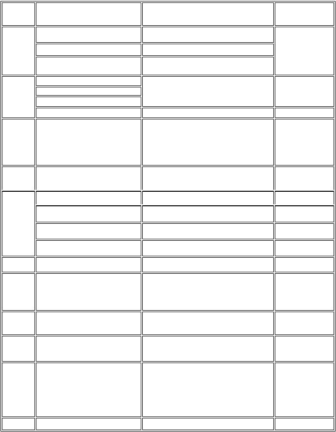
1-1. Adjustment, Periodic Maintenance, Periodic Replacement Parts, and Replacement Consumables by Service Engineer
(1) Adjustment |
|
|
|
|
|
Adjustment |
Timing |
Purpose |
Tool |
Approx. |
|
time |
|||||
|
|
|
|
||
EEPROM |
At logic board ass'y replacement |
To initialize settings other than the following: |
None. |
1 min. |
|
initialization |
|
- USB serial number |
|
|
|
(EEPROM settings) |
|
- Destination setting |
|
|
|
|
|
- Waste ink counter |
|
|
|
|
|
- CD-R correction value |
|
|
|
Destination settings |
At logic board ass'y replacement |
To set the destination. |
None. |
1 min. |
|
(EEPROM settings) |
|
|
|
|
|
Waste ink counter |
- At bottom case unit replacement |
To reset the waste ink counter. |
None. |
1 min. |
|
resetting |
- At ink absorber (QC1-4221 / 4222 / 4223 / |
|
|
|
|
(EEPROM settings) |
4224 / 4263 / 4264 / 4864 / 4257) |
|
|
|
|
|
replacement |
|
|
|
|
CD-R sensor / |
- At logic board ass'y replacement |
To correct the CD-R and automatic print head |
None. (Correction |
2 min. |
|
automatic print head |
- At carriage unit replacement |
alignment sensor. |
performed through |
|
|
alignment sensor |
|
|
service test print) |
|
|
correction (EEPROM |
|
|
|
|
|
settings) |
|
|
|
|
|
Print head alignment |
- At print head replacement |
To ensure accurate dot placement. |
- None. (printer buttons) |
2 min. |
|
|
- At logic board ass'y replacement |
|
- Computer (settings via |
|
|
|
- At carriage unit replacement |
|
the printer driver) |
|
|
Paper feed motor |
At paper feed motor unit replacement |
To adjust the belt tension. (Position the paper |
None. |
2 min. |
|
position adjustment*1 |
|
feed motor so that the belt is stretched tight.) |
|
|
|
Grease application |
- At carriage unit replacement |
- To maintain sliding properties of the carriage, |
- FLOIL KG-107A (QY9- |
1 min. |
|
|
- At chassis' upper gear replacement |
carriage shaft, and shaft lift. |
0057) |
|
|
|
- At shaft lift (QC1-4331) replacement |
- To protect the chassis' upper gear. |
- MOLYKOTE HP300 |
|
|
|
|
|
(QY9-0035) |
|
Note: DO NOT loosen the red screws on both sides of the main chassis, securing the carriage shaft positioning.
*1: Red screws of paper feed motor
The red screws securing the paper feed motor may be loosened only at replacement of the paper feed motor unit.
(2) Periodic maintenance
No periodic maintenance is necessary.
(3) Periodic replacement parts
There are no parts in this printer that require periodic replacement by a service engineer.
(4) Replacement consumables
There are no consumables that require replacement by a service engineer.
1 - 1

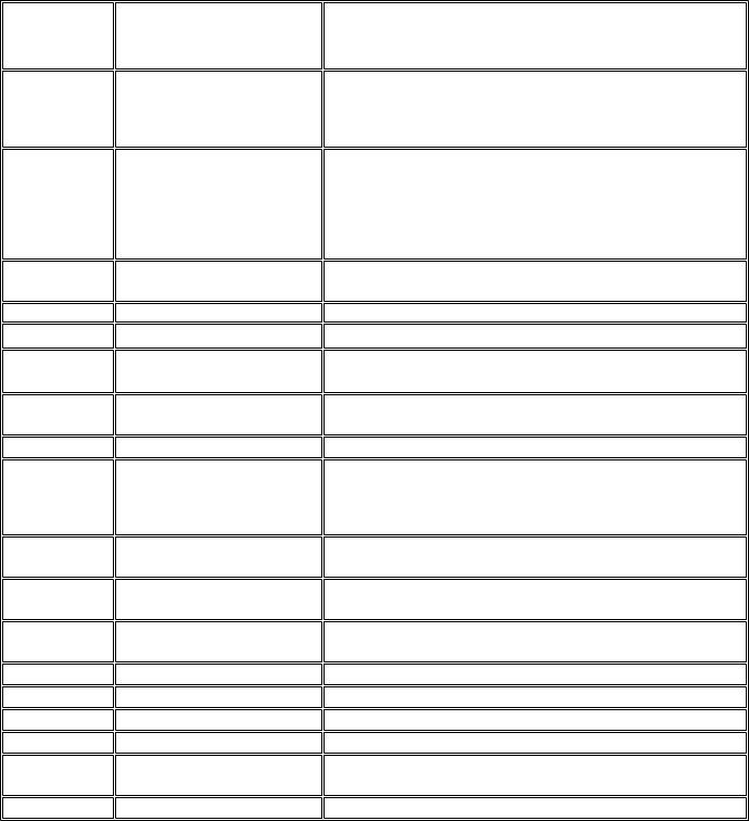
1-2. Customer Maintenance
Adjustment |
Timing |
Purpose |
Tool |
Approx. time |
Print head alignment |
At print head replacement. |
To ensure accurate dot placement. |
- Printer buttons |
3 min. |
|
|
|
- Computer (automatic settings |
|
|
|
|
via the printer driver) |
|
Print head cleaning |
When print quality is not satisfying. |
To improve nozzle conditions. |
- Printer buttons |
1 min. |
|
|
|
- Computer (settings via the |
|
|
|
|
printer driver) |
|
Print head deep |
When print quality is not satisfying, and not |
To improve nozzle conditions. |
Computer (settings via the |
2 min. |
cleaning |
improved by print head cleaning. |
|
printer driver) |
|
Ink tank replacement |
When an ink tank becomes empty. (No ink |
----- |
----- |
2 min. |
|
error) |
|
|
|
Paper feed roller |
When paper does not feed properly. |
To clean the paper feed rollers. |
Printer buttons |
2 min. |
cleaning |
|
|
|
|
CD-R print position |
At CD-R printing, when necessary |
To correct CD-R print position. |
Computer (application |
5 min. |
adjustment |
|
|
software) |
|
Bottom plate cleaning |
When the back side of the paper is smeared |
To clean the platen ribs. |
Computer (application |
1 min. |
|
|
|
software) |
|
1-3. Product Life
(1)Printer
Specified print volume (I) or the years of use (II), whichever comes first.
(I)Print volume
|
|
PIXMA iP4000 |
|
|
18,000 pages |
Black |
1,500 character pattern |
7,200 pages |
Color |
A4, 7.5% duty per color pattern |
5,400 pages |
|
A4, photo, borderless printing |
300 pages |
|
4 x 6, photo, borderless printing |
3,600 pages |
|
Postcard, photo, borderless printing |
1,500 pages |
(II) Years of use
PIXMA iP4000: 5 years of use
(2) Print head
Print volume:
Black
Color
|
PIXMA iP4000 |
|
18,000 pages |
1,500 character pattern |
7,200 pages |
A4, 7.5% duty per color pattern |
5,400 pages |
A4, photo, borderless printing |
300 pages |
4 x 6, photo, borderless printing |
3,600 pages |
Postcard, photo, borderless printing |
1,500 pages |
1 - 2
(3) Ink tank (target value)
PIXMA iP4000:
BCI-3eBK: 740 pages (1,500 character pattern, plain paper / standard mode) 1,500 pages (ISO JIS-SCID No. 5 / plain paper / standard mode)
BCI-6C: 550 pages (ISO JIS-SCID No. 5 / plain paper / standard mode) BCI-6M: 430 pages (ISO JIS-SCID No. 5 / plain paper / standard mode) BCI-6Y: 360 pages (ISO JIS-SCID No. 5 / plain paper / standard mode)
BCI-6BK: 2,000 pages (ISO JIS-SCID No. 5 / plain paper / standard mode)
1-4. Special Tools
Name |
Tool No. |
Application |
Remarks |
MOLYKOTE |
QY9-0035-000 |
To be applied to the chassis' upper gear, and to the sliding |
In common with other |
HP300 |
|
portion of the shaft lift. |
models. |
FLOIL |
QY9-0057-000 |
To be applied to the sliding portion of the carriage, and |
In common with other |
KG-107A |
|
the carriage shaft. |
models. |
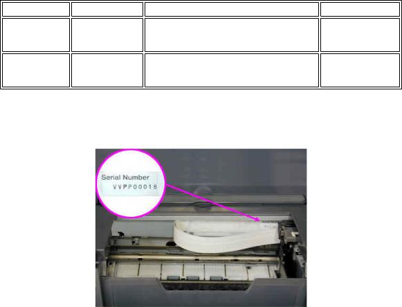
1-5. Serial Number Location
On the carriage flexible cable holder (visible when the access cover is open).
To the top
 <Part 1: 1. MAINTENANCE>
1 - 3
2. LIST OF ERROR DISPLAY / INDICATION
Errors are indicated by the LED, and warnings are displayed on the monitor of the computer connected to the printer.
2-1. Operator Call Errors (by LED Blinking in Orange)
LED blinking |
Error [Error code] |
|
in orange |
||
|
||
2 times |
No paper. (ASF) [1000] |
|
|
No CD-R tray. [1001]*1 |
|
|
No paper in the cassette. [1003] |
|
|
(No paper in the front paper feed cassette.) |
|
3 times |
Paper jam. [1300] |
|
|
Paper jam in the under guide. [1304] |
|
|
Paper jam in the rear guide. [1303] |
|
|
Front door closed. [1250] |
|
4 times |
No ink. [1601 / 1602 / 1611 / 1612 / 1613] |
Solution
Set the paper in the ASF, and press the Resume/Cancel button.
Set the CD-R tray, and press the Resume/Cancel button.
Set the paper in the cassette, and press the Resume/Cancel button.
Remove the jammed paper, and press the Resume/Cancel button.
Open the paper output tray.
Replace the empty ink tank(s), or press the Resume/Cancel button.
Remarks
Pressing the Resume/Cancel button will exit the error without ink tank replacement, however, ink may run out during printing.
5 times |
The print head is not installed [1401], or it is not |
|
properly installed (EEPROM data of the print |
|
head is faulty) [1403 / 1405]. |
Install the print head properly, and close the access cover. Or, with the print head installed, turn the printer off and on.
6 times |
Inner cover open. [1841]*2 |
|
Inner cover open (during printing on paper). |
|
[1846]*2 |
|
CD-R tray guide closed (during CD-R printing). |
|
[1850 / 1855]*1 |
|
CD-R tray guide open (during printing to paper). |
|
[1851 / 1856]*1 |
7 times*1 |
No CD-R or DVD-R. [1002] |
8 times |
Warning: The waste ink absorber becomes |
|
almost full (approx. 95% of the maximum |
|
capacity). [1700] |
Close the inner cover, and press the Resume/Cancel button.
Close the inner cover, and press the Resume/Cancel button.
Open the CD-R tray guide, set the CD-R tray properly, and press the Resume/Cancel button.
Close the CD-R tray guide, and press the Resume/Cancel button.
After setting a CD-R or DVD-R in the tray, set the tray in the tray guide, and press the Resume/Cancel button.
Pressing the Resume/Cancel button will exit the error, and enable printing.
In repair servicing, replace the bottom case unit (QM2-1205), or the ink absorbers (QC1-4222 / 4223 / 4224 / 4263 / 4264 / 4864 / 4221 / 4257).
The service call error, indicating the waste ink absorber is full, is likely to occur soon.
9 times |
The connected digital camera or digital video |
After removing the cable between the camera and the printer, |
|
camera does not support Camera Direct Printing. press the Resume/Cancel button, and re-connect the cable. |
|
|
[2001] |
|
10 times |
Automatic duplex printing cannot be performed |
Press the Resume/Cancel button to eject the paper being used |
|
(paper size not supported). [1310] |
at error occurrence. Printing will resume from on the front |
|
|
side of the next page. |
Data which was to be printed on the back side of paper at error occurrence is skipped (not printed).
11 times |
Failed in automatic print head alignment. [2500] |
Press the Resume/Cancel button, and after confirming the |
|
|
following, perform print head alignment again: |
|
|
- Set an appropriate type and size of paper (plain paper, A4 or |
|
|
letter). |
|
|
- Check that the nozzle check pattern is properly printed (all |
|
|
ink ejected, no faint printing). |
|
|
- Protect the paper output slot from exposure to excessive |
|
|
light. |
|
Access cover open. [1200] |
Close the access cover. |
*1: Only for models supporting CD-R printing |
|
|
*2: Only for models not supporting CD-R printing |
|
|
1 - 4
2-2. Service Call Errors (by LED Blinking in Orange and Green Alternately, or Lit in Orange)
LED alternate blinking |
Error [Error code] |
|
in orange and green |
||
|
||
2 times |
Carriage error [5100] |
Solution
(Replacement of listed parts, which are likely to be faulty)
-Carriage unit (QM2-1209)
-Timing slit strip film (QC1-4284)
-Logic board ass'y (QM2-1548)*1
-Carriage motor (QK1-0545)
3 times |
Paper feed error [6000] |
- Timing sensor unit (QM2-1213) |
|
|
- Timing slit disk film (QC1-4833) |
|
|
- Feed roller ass'y (QL2-0598) |
|
|
- Platen unit (QM2-1215) |
|
|
- Logic board ass'y (QM2-1548)*1 |
|
|
- PAPER FEED MOTOR (QK1-0550) |
4 times |
Purge unit error [5C00] |
- Purge unit (QM2-1210) |
|
|
- Logic board ass'y (QM2-1548)*1 |
5 times |
ASF (cam) sensor error [5700] |
- Sheet feed unit (QM2-1220) |
6 times |
Internal temperature error [5400] |
- Logic board ass'y (QM2-1548)*1 |
7 times |
Waste ink absorber full [5B00] |
- Ink absorber (QC1-4222 / 4223 / 4224 / 4263 / 4264 / 4864 / 4221 / 4257) |
|
|
- Bottom case unit (QM2-1205)*2 |
8 times |
Print head temperature rise error [5200] |
- Print head (QY6-0049) |
|
|
- Logic board ass'y (QM2-1548)*1 |
9 times |
EEPROM error [6800] |
- Logic board ass'y (QM2-1548)*1 |
11 times |
Carriage lift mechanism error [5110] |
- Lift shaft(QC1-4331) |
|
|
- Photo interrupter (WG8-5624) |
|
|
- Sheet feed unit (QM2-1220) |
|
|
- Logic board ass'y (QM2-1548)*1 |
12 times |
AP position error [6A00] |
- Sheet feed unit (QM2-1220) |
|
|
- Logic board ass'y (QM2-1548)*1 |
13 times |
Paper feed position error [6B00] |
- Sheet feed unit (QM2-1220) |
|
|
- Logic board ass'y (QM2-1548)*1 |
14 times |
Paper feed cam sensor error [6B10] |
- Sheet feed unit (QM2-1220) |
|
|
- Logic board ass'y (QM2-1548)*1 |
15 times |
USB Host VBUS overcurrent [9000] |
- Logic board ass'y (QM2-1548)*1 |
16 times |
Valve sensor error [6C00] |
- Logic board ass'y (QM2-1548)*1 |
17 times |
Motor driver error [6D00] |
- Logic board ass'y (QM2-1548)*1 |
20 times |
Other hardware error [6500] |
- Logic board ass'y (QM2-1548)*1 |
Continuous alternate |
ROM error |
- Logic board ass'y (QM2-1548)*1 |
blinking |
|
|
Lights in orange |
RAM error |
- Logic board ass'y (QM2-1548)*1 |
*1: Before replacement of the logic board ass'y, check the waste ink amount (by service test print or EEPROM information print). If the waste ink amount is 7% or more, also replace the bottom case unit (QM2-1205) or the ink absorbers (QC1-4222 / 4223 / 4224 / 4263 / 4264 / 4864 / 4221 / 4257) when replacing the logic board ass'y.
[See Section 3-3. Adjustment / Settings, (6) Service mode, for details.]
*2: Reset the waste ink counter when replacing the bottom case unit.
[See Section 3-3. Adjustment / Settings, (6) Service mode, for details.]
1 - 5
Loading...