


 Loading...
SERVICE
MANUAL
REVISION 0
AUG. 1998 |
FY8-13FB-000 |
COPYRIGHT © 1998 CANON INC. |
CANON NP7161/NP7160 REV.0 AUG. 1998 PRINTED IN JAPAN (IMPRIME AU JAPON) |
Download Service Manual And Resetter Printer at http://printer1.blogspot.com

IMPORTANT
THIS DOCUMENTATION IS PUBLISHED BY CANON INC., JAPAN, TO SERVE AS A SOURCE OF REFERENCE FOR WORK IN THE FIELD.
SPECIFICATIONS AND OTHER INFORMATION CONTAINED HEREIN MAY VARY SLIGHTLY FROM ACTUAL MACHINE VALUES OR THOSE FOUND IN ADVERTISING AND OTHER PRINTED MATTER.
ANY QUESTIONS REGARDING INFORMATION CONTAINED HEREIN SHOULD BE DIRECTED TO THE COPIER SERVICE DEPARTMENT OF THE SALES COMPANY.
THIS DOCUMENTATION IS INTENDED FOR ALL SALES AREAS, AND MAY CONTAIN INFORMATION NOT APPLICABLE TO CERTAIN AREAS.
COPYRIGHT © 1998 CANON INC.
Printed in Japan
Imprimé au Japon
Use of this manual should be
strictly supervised to avoid
disclosure of confidential
information.
Prepared by
OFFICE IMAGING PRODUCTS TECHNICAL SUPPORT DEPT. 1
OFFICE IMAGING PRODUCTS TECHNICAL SUPPORT DIV.
CANON INC.
5-1, Hakusan 7-chome, Toride-shi, Ibaraki 302-8501, Japan
COPYRIGHT © 1998 CANON INC. |
CANON NP7161/NP7160 REV.0 AUG. 1998 PRINTED IN JAPAN (IMPRIME AU JAPON) |
Download Service Manual And Resetter Printer at http://printer1.blogspot.com

Download Service Manual And Resetter Printer at http://printer1.blogspot.com
Download Service Manual And Resetter Printer at http://printer1.blogspot.com
INTRODUCTION
This Service Manual contains basic facts and figures on the NP7161/NP7160 needed to service the machine in the field.
This copier is designed to enable full automatic copying work, and comes with the following systems accessories:
1.ADF-G1*
2.Staper Sorter-L1*
3.MS-C1*
4.Cassette Feeding Module-C1
* NP7161 only.
This Service Manual covers the copier only, and consists of the following chapters:
Chapter 1 General Description introduces the copier’s features and specifications, shows how to operate the copier, and explains how copies are made.
Chapter 2 Basic Operation provides outlines of the copier's various mechanical workings.
Chapter 3 Exposure System discusses the principles of operation used for the copier's lens drive unit and scanner drive unit. It also explains the timing at which these drive units are operated, and shows how they may be disassembled/assembled and adjusted.
Chapter 4 Image Formation System discusses the principles of how images are formed. It also explains the timing at which the various units involved in image formation are operated, and shows how they may be disassembled/ assembled and adjusted.
Chapter 5 Pick-Up/Feeding System explains the principles used from when copy paper is picked up to when a copy is delivered in view of the functions of electrical and mechanical units and in relation to their timing of operation. It also shows how these units may be disassembled/assembled and adjusted.
Chapter 6 Fixing System explains the principles used to fuse toner images to transfer media in view of the functions of electrical and mechanical units and in relation to their timing of operation. It also shows how these units may be disassembled/assembled and adjusted.
Chapter 7 Externals/Auxiliary Mechanisms shows the copier’s external parts, and explains the principles used for the copier’s various control mechanisms in view of the functions of electrical and mechanical units and in relation to their timing of operation. It also shows how these units may be disassembled/assembled and adjusted.
Chapter 8 Installation introduces requirements for the site of installation, and shows how the copier may be installed using step-by-step instructions.
Chapter 9 Maintenance and Servicing provides tables of periodically replaced parts and consumables/durables and scheduled servicing charts.
Chapter 10 Troubleshooting provides tables of maintenance/inspection, standards/ adjustments, and problem identification (image fault/malfunction).
Appendix contains a general timing chart and general circuit diagrams.
COPYRIGHT © 1998 CANON INC. |
CANON NP7161/NP7160 REV.0 AUG. 1998 PRINTED IN JAPAN (IMPRIME AU JAPON) |
i |
Download Service Manual And Resetter Printer at http://printer1.blogspot.com
The following rules apply throughout this Service Manual:
1.Each chapter contains sections explaining the purpose of specific functions and the relationship between electrical and mechanical systems with reference to the timing of operation.
In the diagrams, 


 represents the path of mechanical drive—where a signal name accompanies the symbol
  , the arrow indicates the direction of the electric signal.
The expression “turn on the power” means flipping on the power switch, closing the front door, and closing the delivery unit door, which results in supplying the machine with power.
2.In the digital circuits, ‘1’ is used to indicate that the voltage level of a given signal is “High,” while ‘0’ is used to indicate “Low.” (The voltage value, however, differs from circuit to circuit.)
In practically all cases, the internal mechanisms of a microprocessor cannot be checked in the field. Therefore, the operations of the microprocessors used in the machines are not discussed: they are explained in terms of from sensors to the input of the DC controller PCB and from the output of the DC controller PCB to the loads.
The descriptions in this Service Manual are subject to change without notice for product improvement or other purposes, and major changes will be communicated in the form of Service Information bulletins.
All service persons are expected to have a good understanding of the contents of this Service Manual and all relevant Service Information bulletins and be able to identify and isolate faults in the machine.
ii
COPYRIGHT © 1998 CANON INC. |
CANON NP7161/NP7160 REV.0 AUG. 1998 PRINTED IN JAPAN (IMPRIME AU JAPON) |
Download Service Manual And Resetter Printer at http://printer1.blogspot.com
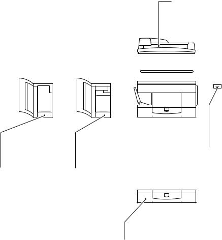
System Configuration
The copier is designed to accommodate the following accessories: *NP7161 only.
ADF-G1*
Feeds a stack of original pages to the copyboard page by page.
MS-C1*
Sorts and groups up to 10 sets of pages automatically.
Stapler Sorter-L1*
In addition to the functions of a 10-bin sorter, staples sorted pages automatically.
Control
Card IV N
Controls volumes of copying work.
Cassette Feeding Module-C1
Provides an additional cassette.
COPYRIGHT © 1998 CANON INC. |
CANON NP7161/NP7160 REV.0 AUG. 1998 PRINTED IN JAPAN (IMPRIME AU JAPON) |
iii |
Download Service Manual And Resetter Printer at http://printer1.blogspot.com
iv
COPYRIGHT © 1998 CANON INC. |
CANON NP7161/NP7160 REV.0 AUG. 1998 PRINTED IN JAPAN (IMPRIME AU JAPON) |
Download Service Manual And Resetter Printer at http://printer1.blogspot.com

CONTENTS
CHAPTER 1 GENERAL DESCRIPTION
I. |
FEATURES .............................................. |
1-1 |
IV. OPERATING THE MACHINE ................ |
1-10 |
||
II. |
SPECIFICATIONS ................................... |
1-2 |
A. Control Panel .................................... |
1-10 |
||
|
A. Copier ................................................. |
1-2 |
B. User Mode ........................................ |
1-12 |
||
|
|
1. |
Type ............................................. |
1-2 |
1. Outline ........................................ |
1-12 |
|
|
2. |
Mechanisms ................................. |
1-2 |
V. ROUTINE MAINTENANCE |
|
|
|
3. |
Performance ................................. |
1-3 |
(BY THE USER) .................................... |
1-14 |
|
|
4. |
Others ........................................... |
1-5 |
VI. PONITS TO NOTE (BY THE USER) ..... |
1-15 |
III. NAMES OF PARTS.................................. |
1-8 |
VII. IMAGE FORMATION ............................. |
1-16 |
|||
|
A. |
External View ..................................... |
1-8 |
A. Outline .............................................. |
1-16 |
|
|
B. |
Cross Section ..................................... |
1-9 |
|
|
|
|
|
1. |
Copier ........................................... |
1-9 |
|
|
CHAPTER 2 BASIC OPERATION
I. BASIC MECHANISMS ............................. |
2-1 |
|
A. Functional Construction ..................... |
2-1 |
|
B. Outline of the Electrical Circuitry ........ |
2-2 |
|
C. Basic Sequence of Operations .......... |
2-4 |
|
1. |
Basic Sequence of Operations at |
|
|
Power-On ..................................... |
2-4 |
2. |
Basic Sequence of Operations at |
|
|
Copy Start .................................... |
2-6 |
D. Main Motor (M1) Control Circuitry ...... |
2-8 |
|
1. |
Outline .......................................... |
2-8 |
2. |
Operation...................................... |
2-8 |
3. |
Detecting an Error ........................ |
2-8 |
E. Inputs to the DC Controller ................ |
2-9 |
|
1. |
Inputs to the |
|
|
DC Controller (1/3) ....................... |
2-9 |
2. |
Inputs to the |
|
|
DC Controller (2/3) ..................... |
2-10 |
3. |
Inputs to the |
|
|
DC Controller (3/3) ..................... |
2-11 |
F. Outputs from the DC Controller ....... |
2-12 |
|
1. |
Outputs from the |
|
|
DC Controller (1/4) ..................... |
2-12 |
2. |
Outputs from the |
|
|
DC Controller (2/4) ..................... |
2-13 |
3. |
Outputs from the |
|
|
DC Controller (3/4) ..................... |
2-14 |
4. |
Outputs from the |
|
|
DC Controller (4/4) ..................... |
2-15 |
G. Inputs to and Outputs from |
|
|
Accessories (1/1) ............................. |
2-16 |
|
COPYRIGHT © 1998 CANON INC. |
CANON NP7161/NP7160 REV.0 AUG. 1998 PRINTED IN JAPAN (IMPRIME AU JAPON) |
v |
Download Service Manual And Resetter Printer at http://printer1.blogspot.com

CHAPTER 3 EXPOSURE SYSTEM
I. |
OUTLINE OF OPERATION ..................... |
3-1 |
1. |
Outline ........................................ |
3-10 |
|
|
A. Changing the Reproduction Ratio ...... |
3-1 |
2. |
Detection of the Original Size |
|
|
II. |
LENS DRIVE SYSTEM ............................ |
3-3 |
|
by the ADF ................................. |
3-10 |
|
|
A. Driving the Lens ................................. |
3-3 |
V. DISASSEMBLY/ASSEMBLY ................. |
3-11 |
||
|
1. |
Outline .......................................... |
3-3 |
A. Scanner Drive Assembly .................. |
3-12 |
|
|
2. |
Motor Control Circuit .................... |
3-4 |
1. |
Removing the Scanner Motor .... |
3-12 |
|
3. |
Moving the Lens ........................... |
3-5 |
2. |
Removing the Scanner Drive |
|
III. SCANNER DRIVE SYSTEM .................... |
3-6 |
|
Cable .......................................... |
3-13 |
||
|
A. Outline ................................................ |
3-6 |
3. |
Routing the Scanner Drive |
|
|
|
B. Scanner Motor Control Circuit ........... |
3-7 |
|
Cable .......................................... |
3-15 |
|
|
C. Relationship between Scanner |
|
4. |
Adjusting the Position |
|
|
|
Sensor and Signals ............................ |
3-7 |
|
of the Mirror ................................ |
3-16 |
|
|
D. Basic Sequence of Operations |
|
5. |
Adjusting the Tension |
|
|
|
(scanner) ........................................... |
3-8 |
|
of the Scanner Drive Cable ........ |
3-17 |
|
|
E. Scanner Movement in |
|
B. Lens Drive Assembly ....................... |
3-18 |
||
|
Page Separation Mode ...................... |
3-9 |
1. |
Removing the Lens Drive |
|
|
IV. OTHERS ................................................. |
3-10 |
|
Motor .......................................... |
3-18 |
||
|
A. Detecting the Original Size .............. |
3-10 |
2. |
Removing the Mirror Motor ........ |
3-19 |
|
CHAPTER 4 IMAGE FORMATION SYSTEM
I. OUTLINE OF THE PROCESSES ............ |
4-1 |
||
A. |
Outline ................................................ |
4-1 |
|
B. Basic Sequence of Operations |
|
||
|
(image formation system) .................. |
4-2 |
|
C. |
Controlling the Intensity of the |
|
|
|
Scanning Lamp .................................. |
4-3 |
|
|
1. |
Outline .......................................... |
4-3 |
|
2. |
Operation...................................... |
4-4 |
|
3. |
Protection Mechanisms ............... |
4-5 |
D. |
Controlling the Primary/Transfer Bias .. |
4-6 |
|
|
1. |
Outline .......................................... |
4-6 |
|
2. |
Turning On/Off the Primary/ |
|
|
|
Transfer Bias ................................ |
4-6 |
E. |
Controlling the Developing/Separation |
||
|
Static Eliminator Bias ......................... |
4-7 |
|
|
1. |
Outline .......................................... |
4-7 |
|
2. |
Turning On/Off the Developing |
|
|
|
DC Bias ........................................ |
4-8 |
|
3. |
Turning On/Off the Developing |
|
|
|
AC Bias/Separation Eliminator |
|
|
|
Bias .............................................. |
4-9 |
|
4. |
Controlling the Developing |
|
|
|
DC Bias to a Specific Voltage |
|
|
|
to Suit Copy Density .................. |
4-10 |
F. |
Controlling the Blank Exposure Lamp ... |
4-12 |
|
|
1. |
Outline ........................................ |
4-12 |
|
2. |
Turning On the Blank Exposure |
|
|
|
Lamp in Reduce Mode ............... |
4-13 |
|
3. |
Turning On the Blank Exposure |
|
|
|
Lamp in Direct/Enlarge Mode .... |
4-13 |
|
4. |
Turning On the Blank Exposure |
|
|
|
Lamp in Multifeeder Mode ......... |
4-13 |
II. DEVELOPING ASSEMBLY/DRUM |
|
||
CLEANER ASSEMBLY .......................... |
4-14 |
||
A. |
Outline .............................................. |
4-14 |
|
B. |
Detecting and Controlling |
|
|
|
the Level of Toner ............................ |
4-16 |
|
C. Monitoring the Waste Toner |
|
||
|
Feeding Screw ................................. |
4-17 |
|
D. Monitoring the Waste Toner Box ..... |
4-18 |
||
E. Control by the Cleaner Thermistor ... |
4-20 |
||
|
1. |
Copying Speed Down |
|
|
|
Sequence ................................... |
4-20 |
F. Auto Density Adjustment (AE) ......... |
4-21 |
||
|
1. |
Outline ........................................ |
4-21 |
|
2. |
Measuring the Density |
|
|
|
of the Original ............................. |
4-21 |
III. DISASSEMBLY/ASSEMBLY ................. |
4-23 |
||
A. Scanning Lamp Assembly ............... |
4-24 |
||
|
1. |
Removing the Scanning Lamp .. |
4-24 |
|
2. |
Mounting the Scanning Lamp .... |
4-25 |
|
3. |
Removing the Thermal Fuse ..... |
4-25 |
B. Exposure Assembly ......................... |
4-26 |
||
|
1. |
Removing the Pre-Exposure/ |
|
|
|
Blank Exposure Lamp |
|
|
|
Assembly .................................... |
4-26 |
|
2. |
Removing the Dust-Proofing |
|
|
|
Glass .......................................... |
4-26 |
|
3. |
Cleaning the No. 6 Mirror ........... |
4-27 |
C. Drum Unit ......................................... |
4-28 |
||
vi
COPYRIGHT © 1998 CANON INC. |
CANON NP7161/NP7160 REV.0 AUG. 1998 PRINTED IN JAPAN (IMPRIME AU JAPON) |
Download Service Manual And Resetter Printer at http://printer1.blogspot.com
1. |
Removing the Drum Unit ........... |
4-28 |
1. |
Outline ........................................ |
4-32 |
2. |
Cleaning the Photosensitive |
|
2. |
Stringing the Charging Wires ..... |
4-32 |
|
Drum ........................................... |
4-29 |
3. |
Adjusting the Height of the |
|
3. |
Removing the Cleaner |
|
|
Charging Wires .......................... |
4-36 |
|
Thermistor .................................. |
4-29 |
G. Developing Assembly....................... |
4-37 |
|
D. Primary Charging Assembly ............ |
4-30 |
1. |
Removing the Developing |
|
|
1. |
Removing the Primary |
|
|
Assembly .................................... |
4-37 |
|
Charging Assembly .................... |
4-30 |
2. |
Removing the Developing |
|
E. Transfer Charging Assembly ........... |
4-31 |
|
Blade .......................................... |
4-37 |
|
1. |
Removing the Transfer |
|
3. |
Removing the Developing |
|
|
Charging Assembly .................... |
4-31 |
|
Cylinder ...................................... |
4-38 |
F. Charging Wire .................................. |
4-32 |
|
|
|
|
CHAPTER 5 PICK-UP/FEEDING SYSTEM
I. OUTLINE OF OPERATION ..................... |
5-1 |
2. |
Mounting the Pick-Up Roller ...... |
5-16 |
||
II. PICK-UP FROM THE CASSETTE .......... |
5-2 |
3. |
Removing the Pick-Up Drive |
|
||
A. |
Pick-Up Operation .............................. |
5-2 |
|
Assembly .................................... |
5-17 |
|
B. Sequence of Operations |
|
4. |
Removing the Pick-Up |
|
||
|
(pick-up/feeding) ................................ |
5-3 |
|
Assembly .................................... |
5-17 |
|
C. Operation of the Cassette Lifter ......... |
5-4 |
5. |
Removing the Feed Roller ......... |
5-18 |
||
D. Detecting the Size of the Cassette .... |
5-6 |
6. |
Removing the Separation Roller .. |
5-18 |
||
|
1. |
Outline .......................................... |
5-6 |
7. |
Mounting the Separation Roller ... |
5-19 |
|
2. |
Detecting the Cassette Size ........ |
5-7 |
B. Multifeeder Assembly ....................... |
5-20 |
|
III. PICK-UP FROM THE MULTIFEEDER .... |
5-8 |
1. |
Removing the Multifeeder Tray .... |
5-20 |
||
A. |
Pick-Up Operation .............................. |
5-8 |
2. |
Removing the Multifeeder |
|
|
B. Detecting the Size of Paper |
|
|
Assembly .................................... |
5-20 |
||
|
in the Multifeeder ................................ |
5-9 |
3. |
Removing the Multifeeder |
|
|
C. Sequence of Operations |
|
|
Pick-Up Roller ............................ |
5-21 |
||
|
(pick-up from multifeeder) ................ |
5-10 |
4. |
Removing the Separation Pad ..... |
5-21 |
|
IV. CONTROLLING THE REGISTRATION |
|
5. |
Adjusting the Pressure of the |
|
||
CLUTCH ................................................. |
5-11 |
|
Separation Pad .......................... |
5-22 |
||
V. DETECTING JAMS ................................ |
5-12 |
C. Registration Roller Assembly ........... |
5-23 |
|||
A. |
Outline .............................................. |
5-12 |
1. |
Removing the Registration |
|
|
B. |
Sequence of Operations |
|
|
Roller Assembly ......................... |
5-23 |
|
|
(jam detection) .................................. |
5-13 |
D. Cassette Assembly .......................... |
5-24 |
||
|
1. |
Registration Delay Jam .............. |
5-13 |
1. |
Removing the Cassette Size |
|
|
2. |
Registration Stationary Jam ....... |
5-13 |
|
Switch ......................................... |
5-24 |
|
3. |
Delivery Delay Jam .................... |
5-14 |
2. |
Changing the Cassette Size |
|
|
4. |
Delivery Stationary Jam ............. |
5-14 |
|
(AB/INCH) .................................. |
5-25 |
VI. DISASSEMBLY/ASSEMBLY ................. |
5-15 |
3. |
Adjusting the Left/Right |
|
||
A. |
Pick-Up Assembly ............................ |
5-16 |
|
Registration ................................ |
5-26 |
|
|
1. |
Removing the Pick-Up Roller..... |
5-16 |
|
|
|
COPYRIGHT © 1998 CANON INC. |
CANON NP7161/NP7160 REV.0 AUG. 1998 PRINTED IN JAPAN (IMPRIME AU JAPON) |
vii |
Download Service Manual And Resetter Printer at http://printer1.blogspot.com

CHAPTER 6 FIXING SYSTEM
I. |
OUTLINE OF OPERATION ..................... |
6-1 |
6. |
Removing the Main Thermistor ... |
6-12 |
||
|
A. |
Outline ................................................ |
6-1 |
7. |
Removing the Sub Thermistor ... |
6-12 |
|
|
B. Controlling the Fixing Temperature ... |
6-2 |
8. |
Removing the Fixing Upper |
|
||
|
C. |
Error Detection Circuit ........................ |
6-5 |
|
Roller .......................................... |
6-13 |
|
|
|
1. |
Outline .......................................... |
6-5 |
9. |
Removing the Fixing Lower |
|
|
|
2. |
Surface Temperature of the |
|
|
Roller .......................................... |
6-14 |
|
|
|
Fixing Upper Roller ...................... |
6-6 |
10. |
Removing the Heat Discharge |
|
|
|
3. |
Activation of the |
|
|
Roller .......................................... |
6-14 |
|
|
|
Fixing Heater (H1) ........................ |
6-6 |
11. |
Adjusting the Height of the |
|
II. |
DISASSEMBLY/ASSEMBLY ................... |
6-7 |
|
Fixing Inlet Guide ....................... |
6-14 |
||
|
A. |
Fixing Assembly ................................. |
6-8 |
12. Adjusting the Nip ........................ |
6-15 |
||
|
|
1. |
Construction ................................. |
6-8 |
B. Delivery Assembly ............................ |
6-16 |
|
|
|
2. |
Locking Mechanism ..................... |
6-8 |
1. |
Removing the Upper |
|
|
|
3. |
Removing the Fixing Assembly ... |
6-8 |
|
Separation Claw ......................... |
6-16 |
|
|
4. |
Removing the Fixing Heater ...... |
6-10 |
2. |
Removing the Lower |
|
|
|
5. |
Removing the Thermal Switch |
|
|
Separation Claw ......................... |
6-16 |
|
|
|
Assembly .................................... |
6-11 |
3. |
Removing the Delivery Roller .... |
6-17 |
CHAPTER 7 EXTERNALS/AUXILIARY MECHANISMS
I. |
FANS |
........................................................ |
7-1 |
|
1. |
Removing the Copyboard |
|
II. |
POWER SUPPLY ..................................... |
7-4 |
|
|
Glass .......................................... |
7-14 |
|
|
A. Outline of Power Supply .................... |
7-4 |
D. |
Fans .................................................. |
7-15 |
||
|
B. Power .......................Supply Circuitry |
7-5 |
|
1. |
Removing the Scanner |
|
|
|
1. ......................... |
AC Power Supply |
7-5 |
|
|
Cooling Fan ................................ |
7-15 |
|
2. ......................... |
DC Power Supply |
7-5 |
|
2. |
Removing the Exhaust Fan ....... |
7-16 |
|
3. |
Mirror Heater, Cassette/ |
|
|
3. |
Remove the Ozone Filter ........... |
7-17 |
|
|
Drum Heater, and Accessory |
|
E. Counter Assembly ............................ |
7-18 |
||
|
........................... |
Cassette Heater |
7-6 |
|
1. |
Removing the Counter |
|
|
4. ............................ |
ADF and Sorter |
7-6 |
|
|
Assembly .................................... |
7-18 |
|
C. Protection Mechanisms of the |
|
F. |
Main Motor Assembly ....................... |
7-18 |
||
|
Power .......................Supply Circuitry |
7-7 |
|
1. |
Removing the Main Motor |
|
|
III. DISASSEMBLY/ASSEMBLY ................... |
7-8 |
|
|
Assembly .................................... |
7-18 |
||
|
A. External ..................................Covers |
7-9 |
G. |
DC Controller PCB ........................... |
7-19 |
||
|
1. .......... |
Removing the Right Door |
7-10 |
|
1. |
Removing the |
|
|
2. |
Removing the Upper |
|
|
|
DC Controller PCB ..................... |
7-19 |
|
................................ |
Right Cover |
7-10 |
|
2. |
Points to Note When Replacing |
|
|
3. |
Removing the Upper |
|
|
|
the DC Controller PCB ............... |
7-19 |
|
................................... |
Left Cover |
7-11 |
H. Removing the Power Supply PCB ... |
7-20 |
||
|
4. |
Removing the Delivery |
|
|
1. |
Removing the |
|
|
............................... |
Lower Cover |
7-11 |
|
|
Power Supply PCB .................... |
7-20 |
|
5. |
Removing the Delivery |
|
I. |
Removing the High-Voltage |
|
|
|
............................... |
Upper Cover |
7-11 |
|
Power Supply PCB ........................... |
7-20 |
|
|
6. |
Removing the Lower |
|
|
1. |
Removing the High-Voltage |
|
|
............................... |
Inside Cover |
7-12 |
|
|
Power Supply PCB .................... |
7-20 |
|
B. Control ....................................Panel |
7-13 |
J. |
Lamp Regulator PCB ....................... |
7-21 |
||
|
1. ...... |
Removing the Control Panel |
7-13 |
|
1. |
Removing the Lamp |
|
|
C. Copyboard .............................Glass |
7-14 |
|
|
Regulator PCB ........................... |
7-21 |
|
viii
COPYRIGHT © 1998 CANON INC. |
CANON NP7161/NP7160 REV.0 AUG. 1998 PRINTED IN JAPAN (IMPRIME AU JAPON) |
Download Service Manual And Resetter Printer at http://printer1.blogspot.com

CHAPTER 8 INSTALLATION
I. SELECTING THE SITE ............................ |
8-1 |
II. UNPACKING AND INSTALLATION ........ |
8-2 |
A. Unpacking .......................................... |
8-2 |
B. Removing the Metal Fixings ............... |
8-3 |
C. Mounting the Drum Unit ..................... |
8-4 |
D. Cleaning the Parts and Making Checks .. |
8-6 |
E. Checking the Images/Operations and |
|
User Mode .......................................... |
8-8 |
F. Supplying Toner ............................... |
8-10 |
III. RELOCATING THE MACHINE .............. |
8-12 |
IV. INSTALLING THE CONTROL |
|
CARD IV N ............................................. |
8-13 |
V. INSTALLING THE REMOTE |
|
DIAGNOSTIC DEVICE II .......................... |
8-14 |
VI. INSTALLING THE ACCESSORY |
|
COUNTER ................................................ |
8-23 |
VII. INSTALLING THE ACCESSORY |
|
HEATER ................................................. |
8-25 |
A. Installing the Heater Switch ............. |
8-25 |
B. Mounting the Cassette/Drum Heater 8-26 |
|
C. Installing the Mirror Heater ............... |
8-27 |
CHAPTER 9 MAINTENANCE AND SERVICING
I. PERIODICALLY REPLACED PARTS ..... |
9-1 |
|
A. |
Copier ................................................. |
9-1 |
II. CONSUMABLES AND DURABLES ........ |
9-2 |
|
A. |
Copier ................................................. |
9-2 |
III. SCHEDULED SERVICING CHART ........ |
9-3 |
IV. SCHEDULED SERVICING TABLE ......... |
9-5 |
A. Copier ................................................. |
9-5 |
CHAPTER 10 TROUBLESHOOTING
I.GUIDE TO TROUBLESHOOTING
TABLES .................................................. |
10-1 |
A.Image Adjustment Basic Procedure 10-3
B.Points to Note for Scheduled Servicing . 10-4
II. STANDARDS AND ADJUSTMENTS |
.... 10-5 |
|
A. Mechanical ....................................... |
10-5 |
|
1. |
Leading Edge Non-Image |
|
|
Width (blank exposure lamp |
|
|
off timing).................................... |
10-5 |
2. |
Image Leading Edge Margin |
|
|
(registration on timing) ............... |
10-5 |
3. |
Left/Right Registration |
|
|
(cassette).................................... |
10-6 |
B. Exposure System ............................. |
10-7 |
|
1. |
Routing the Scanner Drive |
|
|
Cable .......................................... |
10-7 |
2. |
Adjusting the Position |
|
|
of the Mirror ................................ |
10-8 |
3. |
Adjusting the Tension |
|
|
of the Scanner Drive Cable ........ |
10-9 |
C. Image Formation System ............... |
10-10 |
|
1. |
Outline ...................................... |
10-10 |
2. |
Stringing the Charging Wires ... |
10-10 |
3. |
Adjusting the Height of the |
|
|
Charging Wires ........................ |
10-13 |
D. Pick-Up/Feeding System ............... |
10-14 |
|
1. |
Adjusting the Pressure |
|
|
of the Separation Pad .............. |
10-14 |
|
2. |
Changing the Cassette Size |
|
|
|
(AB/INCH) ................................ |
10-14 |
E. |
Fixing System ................................. |
10-16 |
|
|
1. |
Adjusting the Height of the |
|
|
|
Fixing Assembly Inlet Guide .... |
10-16 |
|
2. |
Adjusting the Pressure of |
|
|
|
the Lower Roller (nip) ............... |
10-16 |
F. |
Electrical System ............................ |
10-18 |
|
|
1. |
Obtaining Optimum Exposure ... |
10-18 |
|
2. |
AE Adjustment ......................... |
10-19 |
|
3. |
After Replacing the |
|
|
|
DC Controller PCB ................... |
10-22 |
|
4. |
Checking the Photointerrupters .... |
10-23 |
III. IMAGE FAULTS ................................... |
10-25 |
||
A. |
Initial Checks .................................. |
10-25 |
|
|
1. |
Checking the Site Environment .... |
10-25 |
|
2. |
Checking the Originals ............. |
10-25 |
|
3. |
Checking the Copyboard |
|
|
|
Cover and Copyboard Glass ... |
10-25 |
|
4. |
Checking the Charging |
|
|
|
Assembly .................................. |
10-26 |
|
5. |
Checking the Developing |
|
|
|
Assembly .................................. |
10-26 |
|
6. |
Checking the Paper ................. |
10-26 |
|
7. |
Checking the Periodically |
|
|
|
Replaced Parts ......................... |
10-26 |
|
8. |
Others ....................................... |
10-26 |
COPYRIGHT © 1998 CANON INC. |
CANON NP7161/NP7160 REV.0 AUG. 1998 PRINTED IN JAPAN (IMPRIME AU JAPON) |
ix |
Download Service Manual And Resetter Printer at http://printer1.blogspot.com
B. Image Fault Samples ..................... |
10-28 |
|
17. |
E800 ......................................... |
10-51 |
|
C. Troubleshooting Image Faults ....... |
10-29 |
|
18. |
E805 ......................................... |
10-51 |
|
1. |
The copy is too light. |
|
|
19. |
E821 ......................................... |
10-51 |
|
(halftone area only) .................. |
10-29 |
|
20. |
AC power is absent. ................. |
10-52 |
2. |
The copy is too light. |
|
|
21. |
DC power supply is absent. ..... |
10-53 |
|
(including solid black area) ...... |
10-30 |
|
22. |
The scanner fails to move. ....... |
10-54 |
3. |
The copy is too light. |
|
|
23. |
The lens fails to move. ............. |
10-55 |
|
(entirely, considerably) ............. |
10-30 |
|
24. |
The mirror fails to move. .......... |
10-55 |
4. |
The copy has uneven density. |
|
|
25. |
The scanning lamp |
|
|
(front side dark) ........................ |
10-31 |
|
|
fails to turn on. .......................... |
10-56 |
5. |
The copy has uneven density. |
|
|
26. |
The pre-exposure lamp |
|
|
(front side light) ........................ |
10-31 |
|
|
fails to turn on. .......................... |
10-57 |
6. |
The copy is foggy. (overall) ...... |
10-32 |
|
27. |
The blank exposure lamp |
|
7. |
The copy is foggy. (vertical) ..... |
10-33 |
|
|
fails to turn on. .......................... |
10-57 |
8. |
The copy has black lines. |
|
|
28. |
Pick-up fails. (cassette) ............ |
10-58 |
|
(vertical, fuzzy, thick) ............... |
10-33 |
|
29. |
Pick-up operation fails. |
|
9. |
The copy has black lines. |
|
|
|
(multifeeder) ............................. |
10-59 |
|
(vertical, thin) ............................ |
10-33 |
|
30. |
The registration roller fails |
|
10. |
The copy has white spots. |
|
|
|
to rotate. ................................... |
10-59 |
|
(vertical) .................................... |
10-34 |
|
31. |
The fixing heater fails to |
|
11. |
The copy has white lines. |
|
|
|
turn on. ..................................... |
10-60 |
|
(vertical) .................................... |
10-34 |
|
32. |
The Add Toner indicator |
|
12. |
The copy has white spots. |
|
|
|
does not flash/turn on. ............. |
10-60 |
|
(vertical) .................................... |
10-35 |
|
33. |
The Add Toner indicator fails |
|
13. |
The back of the copy is soiled. .. |
10-36 |
|
|
to turn off. ................................. |
10-61 |
14. |
The copy has faulty fixing. ....... |
10-37 |
|
34. |
The Waste Toner Box Full i |
|
15. |
The copy has a displaced |
|
|
|
ndicator fails to flash/turn on. ... |
10-61 |
|
leading edge. ............................ |
10-38 |
|
35. |
The Waste Toner Box Full |
|
16. |
The copy has a displaced |
|
|
|
indicator fails to turn off. ........... |
10-62 |
|
leading edge. ............................ |
10-38 |
|
36. |
The Add Paper indicator |
|
17. |
The copy has a displaced |
|
|
|
fails to flash. ............................. |
10-62 |
|
leading edge. ............................ |
10-38 |
|
37. |
The Add Paper indicator |
|
18. |
The copy has a blurred image. .. |
10-39 |
|
|
fails to turn off. .......................... |
10-63 |
19. |
The copy is foggy. |
|
|
38. |
The Jam indicator fails to |
|
|
(horizontally) ............................. |
10-39 |
|
|
flash. ......................................... |
10-63 |
20. |
The copy has poor sharpness. .. |
10-40 |
|
39. |
The Jam indicator fails to |
|
21. |
The copy is blank. .................... |
10-41 |
|
|
turn off. ..................................... |
10-64 |
22. |
The copy is solid black. ............ |
10-41 |
|
40. |
The Set Control Card indicator |
|
IV. TROUBLESHOOTING |
|
|
|
fails to turn on. .......................... |
10-64 |
|
MALFUNCTIONS ................................. |
10-42 |
|
41. |
The Set Control Card indicator |
|
|
A. Copier ............................................. |
10-42 |
|
|
fails to turn off. .......................... |
10-65 |
|
1. |
E000 ......................................... |
10-42 |
V. TROUBLESHOOTING FEEDING |
|
||
2. |
E001 ......................................... |
10-43 |
PROBLEMS .......................................... |
10-66 |
||
3. |
E002/E003 ............................... |
10-44 |
A. Copy Jams ..................................... |
10-66 |
||
4. |
E004 ......................................... |
10-45 |
|
1. |
Pick-Up/Feeding Assembly ...... |
10-67 |
5. |
E010 ......................................... |
10-45 |
|
2. |
Fixing/Delivery Assembly ......... |
10-68 |
6. |
E013 ......................................... |
10-46 |
B. |
Faulty Feeding ................................ |
10-69 |
|
7. |
E030 ......................................... |
10-46 |
|
1. |
Double Feeding ........................ |
10-69 |
8. |
E031 ......................................... |
10-47 |
|
2. |
Wrinkles .................................... |
10-69 |
9. |
E202 (The keys on the control |
|
VI. ARRANGEMENT AND FUNCTIONS |
|
||
|
panel fail to operate.) ............... |
10-47 |
OF ELECTRICAL PARTS .................... |
10-70 |
||
10. |
E208 ......................................... |
10-48 |
A. Sensors and Switches ................... |
10-70 |
||
11. |
E210 ......................................... |
10-48 |
B. |
Motors, Fans, Clutches, |
|
|
12. |
E220 ......................................... |
10-49 |
|
and Solenoids ................................. |
10-72 |
|
13. |
E261 ......................................... |
10-49 |
C. Heaters, Lamps, and Others .......... |
10-74 |
||
14. |
E710/E711 ............................... |
10-49 |
D. PCBs .............................................. |
10-76 |
||
15. |
E712 ......................................... |
10-50 |
E. |
Variable Resistors, Light-Emitting |
|
|
16. |
E717 ......................................... |
10-50 |
|
Diodes, and Check Pins by PCB ... |
10-77 |
|
x
COPYRIGHT © 1998 CANON INC. |
CANON NP7161/NP7160 REV.0 AUG. 1998 PRINTED IN JAPAN (IMPRIME AU JAPON) |
Download Service Manual And Resetter Printer at http://printer1.blogspot.com

1. |
DC Controller PCB ................... |
10-77 |
2. |
Power Supply PCB .................. |
10-80 |
3. |
Lamp Regulator PCB ............... |
10-80 |
4. |
High-Voltage Power Supply |
|
|
PCB .......................................... |
10-81 |
VII. SERVICE MODE .................................. |
10-82 |
|
A. Outline ............................................ |
10-82 |
|
B. Using Service Mode ....................... |
10-82 |
|
1. |
Starting Service Mode .............. |
10-82 |
2. |
Selecting Service Mode ........... |
10-82 |
C. Using Adjust Mode and |
|
|
Function Mode ................................ |
10-83 |
|
D. |
Display Mode [1] ............................ |
10-84 |
E. |
I/O Display Mode [2] ....................... |
10-88 |
F. |
Adjust Mode [3] .............................. |
10-92 |
G. |
Function Mode [4] .......................... |
10-94 |
H. |
Option Mode [5] .............................. |
10-95 |
I. |
Counter Mode [6] ........................... |
10-97 |
J. |
Application Mode [7] ....................... |
10-98 |
VIII. SELF DIAGNOSIS .............................. |
10-99 |
|
A. |
Copier ............................................. |
10-99 |
B. |
ADF .............................................. |
10-103 |
C. |
Sorter ............................................ |
10-104 |
D. |
Cassette Feeding Module ............ |
10-104 |
APPENDIX
A. |
GENERAL TIMING CHART ............... |
A-1 |
D. SPECIAL TOOLS LIST ...................... |
A-7 |
B. |
SIGNALS AND ABBREVIATIONS .... |
A-2 |
E. SOLVENTS AND OILS ...................... |
A-8 |
C. |
GENERAL CIRCUIT DIAGRAM ........ |
A-5 |
|
|
COPYRIGHT © 1998 CANON INC. |
CANON NP7161/NP7160 REV.0 AUG. 1998 PRINTED IN JAPAN (IMPRIME AU JAPON) |
xi |
Download Service Manual And Resetter Printer at http://printer1.blogspot.com
Download Service Manual And Resetter Printer at http://printer1.blogspot.com

CHAPTER 1
GENERAL DESCRIPTION
This chapter introduces the copier’s features and specifications, shows how to operate the copier, and explains how copies are made.
I. |
FEATURES .............................................. |
1-1 |
|
II. |
SPECIFICATIONS ................................... |
1-2 |
|
|
A. |
Copier ................................................. |
1-2 |
III. NAMES OF PARTS.................................. |
1-8 |
||
|
A. |
External View ..................................... |
1-8 |
|
B. |
Cross Section ..................................... |
1-9 |
IV. OPERATING THE MACHINE ................ |
1-10 |
||
A. Control Panel .................................... |
1-10 |
B. User Mode ........................................ |
1-12 |
V. ROUTINE MAINTENANCE |
|
(BY THE USER) .................................... |
1-14 |
VI. PONITS TO NOTE (BY THE USER) ..... |
1-15 |
VII. IMAGE FORMATION ............................. |
1-16 |
A. Outline .............................................. |
1-16 |
COPYRIGHT © 1998 CANON INC. |
CANON NP7161/NP7160 REV.0 AUG. 1998 PRINTED IN JAPAN (IMPRIME AU JAPON) |
Download Service Manual And Resetter Printer at http://printer1.blogspot.com
Download Service Manual And Resetter Printer at http://printer1.blogspot.com

CHAPTER 1 GENERAL DESCRIPTION
I.FEATURES
1.The copier is designed light in weight (about 42 kg), and compact in size (566 mm wide, 541mm deep).
2.The copier turns out as many as 16 copies each minute (A4/LTR).
3.The addition of the Cassette Feeding Module-C1 (accessory) enables a source of paper capable of holding a maximum of 1,050 sheets.
4.The density may be adjusted to 33 different shades, or in automatic mode (AE).
5.The use of a photo mode promises faithful reproduction of halftone.
6.The use of an auto power-off function promises power-saving operation.
COPYRIGHT © 1998 CANON INC. |
CANON NP7160/NP7161 REV.0 AUG. 1998 PRINTED IN JAPAN (IMPRIME AU JAPON) |
1–1 |
Download Service Manual And Resetter Printer at http://printer1.blogspot.com

CHAPTER 1 GENERAL DESCRIPTION
II.SPECIFICATIONS
A. Copier
1. Type
Body |
Desktop |
|
|
Copyboard |
Fixed |
|
|
Light source |
Halogen lamp (120V:200W/230V:220W) |
|
|
Lens |
Lens array |
|
|
Photosensitive material |
OPC (30 dia.) |
|
|
2. Mechanisms
Copying |
Indirect electrostatic |
||
|
|
|
|
Charging |
Corona |
||
|
|
|
|
Exposure |
Slit (moving light source) |
||
|
|
|
|
Copy density adjustment |
Auto or manual |
||
|
|
|
|
Development |
Dry (toner projection) |
||
|
|
|
|
Pick-up |
Auto |
Front cassette (1 pc.) |
|
|
|
||
Manual |
Multifeeder (5 mm deep approx.; about 50 sheets of 80 g/m2 paper) |
||
|
|||
Transfer |
Corona |
||
|
|
|
|
Separation |
Curvature + static eliminator |
||
|
|
|
|
Cleaning |
Blade |
||
|
|
|
|
Fixing |
Heat roller (1000 W for 120V model; 1050 W for 230V model) |
||
|
|
|
|
1–2 |
COPYRIGHT © 1998 CANON INC. |
CANON NP7160/NP7161 REV.0 AUG. 1998 PRINTED IN JAPAN (IMPRIME AU JAPON) |
Download Service Manual And Resetter Printer at http://printer1.blogspot.com
|
|
|
|
|
CHAPTER 1 GENERAL DESCRIPTION |
|
|
|
|
|
|
|
|
|
|
3. Performance |
|
|
|
|
|||
|
|
|
|
||||
|
|
|
|
|
|
||
Original type |
|
Sheet, book, 3-D object (2 kg max.) |
|
||||
|
|
|
|
|
|||
Maximum original size |
A3/279 × 432 mm (11"×17") |
|
|||||
|
|
|
|
|
|
|
|
|
|
|
Direct |
1:1.000 |
|
|
|
|
|
|
|
|
|
|
|
|
|
|
Reduce I |
1:0.5000 |
|
|
|
|
|
|
|
|
|
|
|
|
|
|
Reduce II |
1:0.707 |
|
|
|
|
|
|
|
|
|
|
|
|
|
|
Reduce III |
1:0.0816 |
|
|
|
|
|
|
|
|
|
|
|
Reproduction |
Reduce IV |
1:0.0865 |
|
|
|
||
ratio |
|
|
|
|
|
|
|
|
Enlarge I |
1:1.154 |
|
|
|
||
|
|
|
|
|
|
||
|
|
|
|
|
|
|
|
|
|
|
Enlarge II |
1:1.224 |
|
|
|
|
|
|
|
|
|
|
|
|
|
|
Enlarge III |
1:1.414 |
|
|
|
|
|
|
|
|
|
|
|
|
|
|
Enlarge IV |
1:2.000 |
|
|
|
|
|
|
|
|
|
||
|
|
|
Zoom |
1:0.500 to 2.000 (in 1% increments) |
|
||
|
|
|
|
|
|
||
Wait time |
|
30 sec or less (at 20°C room temperature) |
|
||||
|
|
|
|
||||
First copy |
|
5.8 sec or less (A4, Direct, non-AE, cassette) |
|
||||
|
|
|
|||||
Continuous copying |
999 sheets max. |
|
|||||
|
|
|
|
||||
Copy size |
|
A3/279×432 mm (11"×17") max. B5R/STMTR min. |
|
||||
|
|
|
|
|
|
||
|
|
|
Cassette |
• Plain paper (64 to 80 g/m2) |
|
||
|
|
|
|
A3, B4, A4R, A4, B5R,B5, 279 × 432 mm (11"×17"), LTRR, LTR, LGL |
|
||
|
|
|
|
• Colored paper (recommended by Canon) |
|
||
|
|
|
|
B4, A4 |
|
||
|
|
|
|
|
|
||
|
|
|
|
• Plain paper (64 to 80 g/m2) |
|
||
Copy paper |
|
|
A3, B4, A4R, A4, B5R, B5, A5, 279X432 mm (11"×17"), LTRR, |
|
|||
type |
|
Multifeeder |
LTR, LGL, STMTR |
|
|||
|
|
|
|
||||
|
|
|
|
• Tracing paper (SM-1, GNT80) |
|
||
|
|
|
|
A3, B4, A4R, A4, B5R, B5, A5 |
|
||
|
|
|
|
• Transparency (recommended by Canon) |
|
||
|
|
|
|
A4/LTR |
|
||
|
|
|
|
• Colored paper (recommended by Canon)* |
|
||
|
|
|
|
B4, A4 |
|
||
|
|
|
|
• Label paper (recommended by Canon) |
|
||
|
|
|
|
A4/LTR |
|
||
|
|
|
|
• Heavy paper (up to 128 g/m2) |
|
||
|
|
|
|
|
|
|
|
*May be used, but may not feed properly.
COPYRIGHT © 1998 CANON INC. |
CANON NP7160/NP7161 REV.0 AUG. 1998 PRINTED IN JAPAN (IMPRIME AU JAPON) |
1–3 |
Download Service Manual And Resetter Printer at http://printer1.blogspot.com

CHAPTER 1 GENERAL DESCRIPTION
Cassette |
Claws |
Used |
|
|
Frame |
55 mm deep (500 sheets of 80 g/m2 paper; 250 sheets if B5) |
|||
|
||||
Copy tray |
|
100 sheets approx. (plain paper ; 64 to 80 g/m2) |
||
|
Leading edge |
Direct 2.0 ±1.0 mm |
|
|
Non-image |
Trailing edge |
Direct 2.5 ±1.5 mm |
|
|
width |
|
Direct 2.5 ±2.0 mm |
|
|
|
Left/right |
|
||
Auto clear |
|
Provided (2 min standard; may be changed between 1 and 9 min |
||
|
||||
|
|
in 1-min increments) |
|
|
Auto power-off |
Provided (30 min standard; may be changed between 10 and 90 min |
|||
|
|
in 10-min increments) |
|
|
|
|
|||
Auto pre-heat |
Provided (15 min standard; may be changed between 15 and 90 min |
|||
|
|
in 15-min increments) |
|
|
|
|
|
|
|
Accessories |
|
• ADF-G1* |
• Cassette Feeding Module-C1 |
|
|
|
• MS-C1* |
• Stapler Sorter-L1* |
|
|
|
• Control Card IV N |
• Remote Diagnostic Device II |
|
|
|
|
|
|
*Applies to the NP7161 only.
1–4 |
COPYRIGHT © 1998 CANON INC. |
CANON NP7160/NP7161 REV.0 AUG. 1998 PRINTED IN JAPAN (IMPRIME AU JAPON) |
Download Service Manual And Resetter Printer at http://printer1.blogspot.com
CHAPTER 1 GENERAL DESCRIPTION
4. Others
|
Temperature |
7.5°to 32.5°C/45.5°to 90.5°F |
|
||
|
|
||||
Operating |
Humidity |
5% to 80% RH |
|
||
conditions |
|
||||
Atmospheric |
810.6 to 1013.3 hPa (0.8 to 1.0 atm) |
|
|||
|
|
||||
|
pressure |
|
|
|
|
|
|
|
|
||
|
|
NP7160 |
|
NP7161 |
|
|
120V |
NLB xxxxx |
|
---- |
|
Power |
120V (UL) |
---- |
|
NLD xxxxx |
|
source |
|
||||
|
|
|
|
||
|
127V |
NLC xxxxx |
|
---- |
|
|
230V |
PHQ xxxxx |
|
PHS xxxxx |
|
|
|
|
|
|
|
Power |
Maximum |
1.5 kW or less |
|
||
|
|
|
|
||
Standby |
0.135 kWh (approx.; reference only) |
|
|||
consumption |
|
||||
|
Continuous |
0.645 kWh (approx.; reference only) |
|
||
|
|
|
|
||
Noise |
Copying |
66 dB or less (sound power level by ISO method) |
|||
|
|
|
|
||
Standby |
40 dB or less (sound power level by ISO method) |
||||
|
|||||
|
|
|
|
|
|
Ozone (8-hr average) |
0.05 ppm or less |
|
|||
|
|
|
|
|
|
|
Width |
566 mm/22.3 in |
|
||
|
|
|
|
|
|
Dimensions |
Depth |
541 mm/21.3 in |
|
||
|
|
|
|
|
|
|
Height |
389 mm/15.3 in |
|
||
|
|
|
|
|
|
Weight |
|
NP7160 |
|
NP7161 |
|
|
|
|
|
||
|
42 kg/92.6 lb (approx.) |
|
42 kg/92.6 lb (approx.) |
||
|
|
|
|||
|
|
|
|
|
|
Consumables |
Copy paper |
Keep wrapped, and avoid humidity. |
|
||
|
|
|
|
||
Toner |
Avoid direct sunlight, and store at 40°C, 85% or less. |
||||
|
|||||
|
|
|
|
|
|
Specifications subject to change without notice.
COPYRIGHT © 1998 CANON INC. |
CANON NP7160/NP7161 REV.0 AUG. 1998 PRINTED IN JAPAN (IMPRIME AU JAPON) |
1–5 |
Download Service Manual And Resetter Printer at http://printer1.blogspot.com

CHAPTER 1 GENERAL DESCRIPTION
Reproduction mode |
Size |
Copy paper |
Copies/min |
||
|
|
|
|
|
|
|
|
A3 (297 × 420mm) |
A3 |
9 |
|
|
|
|
|
|
|
|
|
A4 (210 × 297mm) |
A4 |
16 |
|
|
|
|
|
|
|
Direct |
(100%) |
B4 (257 × 364mm) |
B4 |
11 |
|
|
|
|
|||
B5 (182 × 257mm) |
B5 |
17 |
|||
|
|
||||
|
|
|
|
|
|
|
|
A4R (297 × 210mm) |
A4R |
13 |
|
|
|
|
|
|
|
|
|
B5R (257 × 182mm) |
B5R |
14 |
|
|
|
|
|
|
|
|
I |
A3 → A4R |
A4R |
11 |
|
|
(70.7%) |
|
|
|
|
|
B4 → B5R |
B5R |
13 |
||
|
|
||||
Reduce |
II |
B4 → A4R |
A4R |
12 |
|
|
(81.6%) |
|
|
|
|
|
|
|
|
|
|
|
III |
A3 → B4 |
B4 |
10 |
|
|
(86.5%) |
|
|
|
|
|
A4 → B5 |
B5 |
17 |
||
|
|
||||
|
I |
A5R → A3 |
A3 |
8 |
|
|
(200%) |
|
|
|
|
|
|
|
|
|
|
|
II |
A4R → A3 |
A3 |
8 |
|
|
(141.4%) |
|
|
|
|
Enlarge |
B5R → B4 |
B4 |
9 |
||
|
|||||
III |
A4R → B4 |
B4 |
9 |
||
|
|||||
|
(122.4%) |
|
|
|
|
|
|
|
|
|
|
|
IV |
B4 → A3 |
A3 |
8 |
|
|
(115.4%) |
|
|
|
|
|
B5 → A4 |
A4 |
11 |
||
|
|
||||
Specifications subject to change without notice.
1–6 |
COPYRIGHT © 1998 CANON INC. |
CANON NP7160/NP7161 REV.0 AUG. 1998 PRINTED IN JAPAN (IMPRIME AU JAPON) |
Download Service Manual And Resetter Printer at http://printer1.blogspot.com

|
|
|
|
CHAPTER 1 |
GENERAL DESCRIPTION |
|
|
|
|
|
|
|
|
|
|||
|
|
|
|
|
|
|
|
|
|
|
|
|
|
|
|
|
|
Reproduction mode |
Size |
Copy paper |
|
Copies/min |
|
|
||
|
|
|
|
|
|
|
|
|
|
|
11" × 17" (279 × 432mm) |
11" × 17" |
|
9 |
|
|
|
|
|
|
|
|
|
|
|
|
Direct |
(100%) |
LTR (297 × 216mm) |
|
LTR |
|
16 |
|
|
|
|
|
|
|
|
|
||
LGL (216 × 356mm) |
|
LGL |
|
11 |
|
|
||
|
|
|
|
|
|
|||
|
|
|
|
|
|
|
|
|
|
|
LTRR (216 × 297mm) |
|
LTRR |
|
13 |
|
|
|
|
|
|
|
|
|
|
|
|
I |
11" × 17" → LTRR |
|
LTRR |
|
12 |
|
|
|
(64.7%) |
|
|
|
|
|
|
|
|
|
|
|
|
|
|
|
|
Reduce |
II |
11" × 17" → LGL |
|
LGL |
|
11 |
|
|
(73.3%) |
|
|
|
|
|
|
|
|
|
|
|
|
|
|
|
|
|
|
|
|
|
|
|
|
|
|
|
III |
LGL → LTRR |
|
LTRR |
|
12 |
|
|
|
(78.6%) |
|
|
|
|
|
|
|
|
|
|
|
|
|
|
|
|
|
I |
STMTR → 11" × 17" |
11" × 17" |
|
8 |
|
|
|
|
(200%) |
|
|
|
|
|
|
|
|
|
|
|
|
|
|
|
|
Enlarge |
II |
LTRR → 11" × 17" |
11" × 17" |
|
8 |
|
|
|
(129.4%) |
|
|
|
|
|
|
|
|
|
|
|
|
|
|
|
|
|
|
|
|
|
|
|
|
|
|
|
III |
LGL → 11" × 17" |
11" × 17" |
|
8 |
|
|
|
|
(121.4%) |
|
|
|
|
|
|
|
|
|
|
|
|
|
|
|
|
Specifications subject to change without notice.
COPYRIGHT © 1998 CANON INC. |
CANON NP7160/NP7161 REV.0 AUG. 1998 PRINTED IN JAPAN (IMPRIME AU JAPON) |
1–7 |
Download Service Manual And Resetter Printer at http://printer1.blogspot.com
CHAPTER 1 GENERAL DESCRIPTION
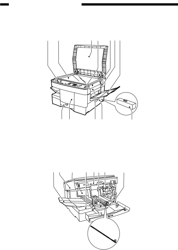
III. NAMES OF PARTS
A. External View [1] [2] |
[3] [4] [5] [6] [7] |
|
|
[12] [11] |
[10] [9] |
|
[8] |
|
[1] |
Control panel |
[5] |
Upper right cover |
[9] |
Right door |
|
[2] |
Copyboard glass |
[6] |
Upper rear cover |
[10] |
Right cover |
|
[3] |
Copyboard cover |
[7] |
Multifeeder |
|
[11] |
Front door |
[4] |
Power switch |
[8] |
Waste toner box |
[12] |
Cassette |
|
Figure 1-301
[1] [2] |
[3] |
[4] [5] [6] [7] |
[9]
[1] |
Copy tray |
[4] |
Lower delivery cover |
[2] |
Upper left cover |
[5] |
Front fixing cover |
[3] |
Upper delivery cover |
[6] |
Inside cover |
[8]
[7]Open/close lever
[8]Lower inside cover
[9]Static eliminator
Figure 1-302
1–8 |
COPYRIGHT © 1998 CANON INC. |
CANON NP7160/NP7161 REV.0 AUG. 1998 PRINTED IN JAPAN (IMPRIME AU JAPON) |
Download Service Manual And Resetter Printer at http://printer1.blogspot.com
CHAPTER 1 GENERAL DESCRIPTION
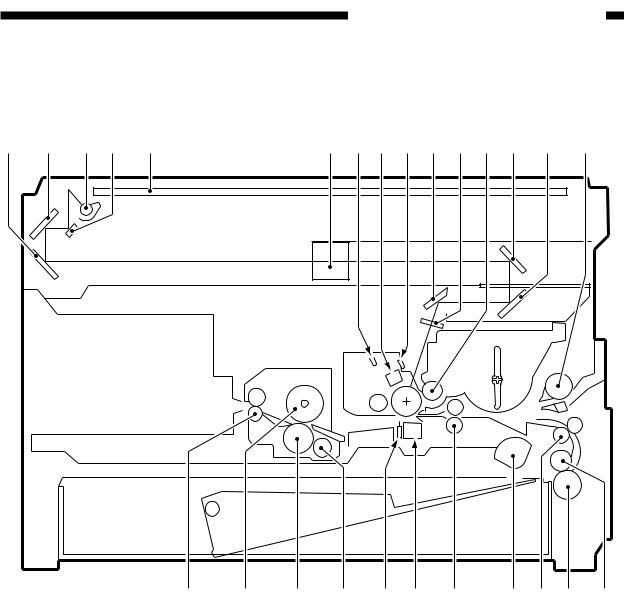
B. Cross Section
1. Copier
[1] |
[2] |
[3] |
[4] |
[5] |
[6] |
[7] [8] |
[9] [10] [11] [12] [13] |
[14] |
[15] |
[26] |
[25] |
[24] |
[23] |
[22] [21] |
[20] |
[19] [18] [17] |
[16] |
[1] |
No. 3 mirror |
[11] |
Dust-proofing glass |
[21] |
Transfer charging assembly |
[2] |
No. 2 mirror |
[12] |
Developing cylinder |
[22] |
Separation static eliminator |
[3] |
Scanning lamp |
[13] |
No. 4 mirror |
[23] |
Heat discharging roller |
[4] |
No. 1 mirror |
[14] |
No. 5 mirror |
[24] |
Lower fixing roller |
[5] |
Copyboard glass |
[15] |
Multifeeder pick-up roller |
[25] |
Upper fixing roller |
[6] |
Lens |
[16] |
Feed roller |
[26] |
Delivery roller |
[7] |
Pre-exposure lamp |
[17] |
Separation roller |
|
|
[8] |
Primary charging assembly |
[18] |
Vertical path roller |
|
|
[9] |
Blank exposure lamp |
[19] |
Pick-up roller |
|
|
[10] |
No. 6 mirror |
[20] |
Registration roller |
|
|
Figure 1-303
COPYRIGHT © 1998 CANON INC. |
CANON NP7160/NP7161 REV.0 AUG. 1998 PRINTED IN JAPAN (IMPRIME AU JAPON) |
1–9 |
Download Service Manual And Resetter Printer at http://printer1.blogspot.com
CHAPTER 1 GENERAL DESCRIPTION
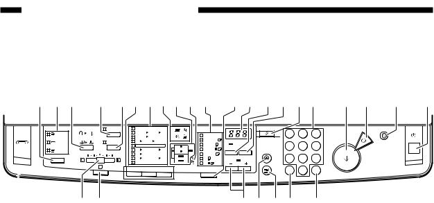
IV. OPERATING THE MACHINE
A. Control Panel
[1] [2] [3] |
[4] [5] [6] [7] [8] [9][10] [11] |
[12][13] [14][15] [16][17] |
[18] 1[9] |
[20] |
[21] |
Image Combination |
Fit Image |
Max. 200% |
|
|
1 2 3 |
|
|
|
Reset |
||
Sort |
|
A4/LTR |
A3 B5 |
B4 |
Auto Paper |
|
|
|
|||
|
A4/LTR |
B4 |
|
|
|
|
|
||||
Two-page Separation |
|
|
|
A3/1117 |
|
|
|
|
|||
Staple- |
Photo |
B4 |
A3 B5 A4/LTR |
|
|
|
|
||||
Sort |
|
|
1 : 1 |
|
|
A4/LTR |
|
|
|
|
|
|
|
|
|
|
|
Auto Zoom |
% |
|
|||
Group |
|
A3 |
B4 A4/LTR |
B5 |
A4/LTR R |
Additional |
|||||
|
|
|
|||||||||
|
B4/LGL |
|
|
|
Functions |
||||||
|
|
B4 |
A4/LTR |
|
|
|
|
|
|||
|
|
|
|
|
|
|
|
||||
|
|
A3 |
A4/LTR B4 |
B5 |
B5 |
U1 |
|
|
|
||
|
A |
Min. 50% |
|
|
B5 R |
U2 |
Zoom |
|
Interrupt |
||
|
Reduce |
|
1 : 1 |
Enlarge |
Paper Select |
|
|
|
|||
|
|
|
|
|
|
||||||
1 2 3
4 5 6
7 8 9
ID 0 C
Energy Saver
Stop
ON/OFF
Start
Clear
|
|
[22] [23] |
|
|
[24][25] [26][27] [28] |
|
|
|
|
|
|
Figure 1-401 |
|
|
|
|
|
|
|
|
|
Ref. |
Name |
|
|
Description |
Remarks |
|
|
|
|
|
|
|
|
|
Sorter key* |
|
Press it to select or deselect Sort, Staple Sort, or |
*Requires a sorter or |
|
|
[1] |
|
|
Group Sort mode. |
stapler sorter. |
|
|
|
|
|
|
|
|
|
[2] |
Sorter indicator* |
|
Indicates the selected delivery mode. It remains |
|
|
|
|
|
off in non-sort mode. |
|
||
|
|
|
|
|
||
|
|
|
|
|
|
|
|
[3] |
2-on-1*/Page |
|
Press it to select or deselect 2-on-1 or Page |
*Requires an ADF. |
|
|
Separate key |
|
Separate mode. |
|
||
|
|
|
|
|||
|
|
|
|
|
|
|
|
[4] |
Fit Page key |
|
Press to select or deselect Fit Page mode. Use |
|
|
|
|
|
the mode to make a copy covering all image area |
|
||
|
|
|
|
of the original. |
|
|
|
|
|
|
|
|
|
|
[5] |
Photo key |
|
Press it to select or deselect Photo mode. |
|
|
|
|
|
|
|
|
|
|
[6] |
Reduce/Direct/ |
|
Press it to select Reduce/Enlarge (default ratio) or |
|
|
|
Enlarge key |
|
reset any ratio to Direct. |
|
||
|
|
|
|
|||
|
|
|
|
|
|
|
|
[7] |
Default Ratio indicator |
|
Indicates the selected default reproduction ratio. |
|
|
|
|
|
|
|
|
|
|
|
Control Card indicator |
|
Flashes when the control card is not set properly. |
Requires a Control |
|
|
|
|
|
|
|
Card Unit. |
|
|
|
|
|
|
|
|
|
Jam indicator |
|
Flashes when a jam occurs. |
|
|
|
[8] |
|
|
|
|
|
|
Toner indicator |
|
Flashes when toner is running out. It stops |
|
||
|
|
|
|
flashing and remains on when toner runs out |
|
|
|
|
|
|
completely. |
|
|
|
|
|
|
|
|
|
|
|
Paper indicator |
|
Flashes if paper runs out in the selected cassette |
|
|
|
|
|
|
or the manual feed tray (or, when the cassette is |
|
|
|
|
|
|
not set properly). |
|
|
|
|
|
|
|
|
|
|
|
Paper Source/Jam |
|
Indicates the selected cassette or the manual tray; |
|
|
|
[9] |
|
|
flashes the location of a jam, if any. (It also |
|
|
|
|
|
flashes when a jam occurs in the ADF or when the |
|
||
|
|
|
|
|
||
|
|
|
|
sorter or the right door needs to be checked.) |
|
|
|
|
|
|
|
|
|
|
* Applies to the NP7161 only |
|
Table 1-401 |
|
||
|
|
|
|
|
|
|
1–10 |
COPYRIGHT © 1998 CANON INC. |
CANON NP7160/NP7161 REV.0 AUG. 1998 PRINTED IN JAPAN (IMPRIME AU JAPON) |
||||
Download Service Manual And Resetter Printer at http://printer1.blogspot.com

CHAPTER 1 GENERAL DESCRIPTION
Ref. |
Name |
|
Description |
Remarks |
|
|
|
|
|
[10] |
Location indicator |
|
Flashes when the waste toner box needs to be |
|
|
|
replaced. When the case becomes full, it stops |
|
|
|
|
|
|
|
|
|
|
flashing and remains on. |
|
|
|
|
|
|
[11] |
Paper Size indicator |
|
Indicates the size of the paper in the cassette |
|
|
|
|
selected by the Paper Select key. |
|
|
|
|
|
|
[12] |
Paper Select key |
|
Press it to select Auto Paper Select*, Cassette, or |
*Requires an ADF. |
|
|
Manual Feed Tray mode. |
|
|
|
|
|
|
|
|
|
|
|
|
[13] |
Copy Count/Ratio |
|
Indicates the copy count/ratio and the selected |
|
indicator |
|
user mode. |
|
|
|
|
|
||
|
|
|
|
|
|
Auto Ratio key* |
|
Use it to select or deselect Auto Ratio mode, in |
*Requires an ADF. |
[14] |
|
|
which the best reproduction ratio is automatically |
|
|
|
selected to suit the original and the selected |
|
|
|
|
|
|
|
|
|
|
paper. |
|
|
|
|
|
|
[15] |
% key |
|
Press it to indicate the selected reproduction ratio. |
|
|
|
|
|
|
[16] |
Reset key |
|
Use it to reset the current copy mode to default. |
|
|
|
|
|
|
[17] |
Keypad |
|
Use it to set a copy count or to enter a numeric value. |
|
|
|
|
|
|
[18] |
Start key |
|
Press it to start copying. |
|
|
|
|
|
|
[19] |
Stop key |
|
Press it to stop continuous copying. |
|
|
|
|
|
|
[20] |
Power Save key |
|
Press it to select or deselect power save mode. |
|
|
|
|
|
|
[21] |
Power switch |
|
Press it to turn on or off the power. |
|
|
|
|
|
|
[22] |
Copy Density |
|
Slide it to adjust the copy density manually. |
|
lever |
|
|
|
|
|
|
|
|
|
|
|
|
|
|
[23] |
AE key |
|
Press it to select or deselect AE (auto density |
|
|
|
adjustment) mode. |
|
|
|
|
|
|
|
|
|
|
|
|
[24] |
Zoom key |
|
Press it to select a reproduction ratio (50% to |
|
|
|
200%) in 1% increments. Hold it down to |
|
|
|
|
|
increase/decrease the ratio continuously. |
|
|
|
|
|
|
[25] |
User Mode key |
|
Press it to set or change user mode settings. |
|
|
|
|
|
|
[26] |
Interrupt key |
|
Press it to stop an ongoing copying run to make a |
|
|
|
copy of a different original. |
|
|
|
|
|
|
|
|
|
|
|
|
[27] |
ID key |
|
Press it after entering an appropriate ID number. |
|
|
|
Press it also after entering a number for ID |
|
|
|
|
|
registration. |
|
|
|
|
|
|
[28] |
Clear key |
|
Press it to reset the copy count to 1 or to clear any |
|
|
|
wrong input when making settings. |
|
|
|
|
|
|
|
|
|
|
|
|
* Applies to the NP7161 only |
|
|
||
Table 1-402
COPYRIGHT © 1998 CANON INC. |
CANON NP7160/NP7161 REV.0 AUG. 1998 PRINTED IN JAPAN (IMPRIME AU JAPON) |
1–11 |
Download Service Manual And Resetter Printer at http://printer1.blogspot.com

CHAPTER 1 GENERAL DESCRIPTION
B. User Mode
1.Outline
The copier provides user modes, which may be changed freely by the user. These modes
provide the functions shown in the following table.
Notation |
Item |
Description |
Factory settings |
|
(default) |
||||
|
|
|
||
|
|
|
|
|
U00 |
Resetting |
Use it to reset new settings made in user |
– |
|
user mode |
mode to default settings. |
|
||
|
|
|
|
|
|
Changing auto |
Use it to set the auto clear time length |
2 min |
|
U01 |
clear time |
between 1 an 9 min in 1-min increments. |
|
|
|
Setting it to 0 disables the auto-clear |
|
||
|
|
function. |
|
|
|
|
|
|
|
U02 |
Changing auto |
Use it to select an appropriate auto power- |
15 min |
|
power-save time |
save time length: 10, 15, 20, 30, 40, 50, 60, |
|
||
|
|
or 90 min (8 lengths). |
|
|
|
|
|
|
|
U03 |
Changing auto |
Use it to select an appropriate auto power- |
30 min |
|
power-off time |
off time length: 10, 15, 20, 30, 40, 50, 60, 90 |
|
||
|
|
(8 lengths). |
|
|
|
|
|
|
|
|
Fine-adjusting |
Use it to adjust vertical and horizontal |
±0.0% |
|
U04 |
Zoom |
reproduction ratios over ±5 grades in 0.2% |
|
|
|
increments. |
|
||
|
|
Rang: -1.0% to +1.0% in units of 0.2% |
|
|
|
|
|
|
|
|
Turning on/off |
Use it to turn on/off the auto cassette change |
ON |
|
|
auto cassette |
function, in which copying is continued by |
|
|
U05 |
change |
switching cassettes when the selected |
|
|
|
cassette runs out of paper. |
|
||
|
|
|
||
|
|
O N : Enable auto cassette change. |
|
|
|
|
OFF : Disable auto cassette change. |
|
|
|
|
|
|
|
|
Turning on/off |
Use it to turn on/off the auto sort function, in |
ON |
|
|
auto sort |
which sorting takes place when making |
|
|
U06 |
|
multiple copies of multiple originals using |
|
|
|
an ADF. |
|
||
|
|
O N : Enable auto sort. |
|
|
|
|
OFF : Disable auto sort. |
|
|
|
|
|
|
|
|
Turning on/off |
Use it to turn on/off auto counting of |
OFF |
|
U07 |
ADF jam |
originals in ADF jam recovery. |
|
|
recovery |
O N : Enable auto count. |
|
||
|
|
OFF : Disable auto count. |
|
|
|
|
|
|
|
U08 |
Cleaning feeder |
Use it to clean the feeder (after placing |
– |
|
|
paper in the ADF and pressing the Start |
|
||
|
|
key). |
|
|
|
|
|
|
1–12 |
COPYRIGHT © 1998 CANON INC. |
CANON NP7160/NP7161 REV.0 AUG. 1998 PRINTED IN JAPAN (IMPRIME AU JAPON) |
Download Service Manual And Resetter Printer at http://printer1.blogspot.com
Loading...