


Español Français English
INSTRUCTION MANUAL
MODE D’EMPLOI
MANUAL DE INSTRUCCIONES
English

Thank you for purchasing a Canon product.
The Canon Macro Ring Lite MR-14EX and Macro Twin Lite MT-24EX are macro flash units compatible with E-TTL II/E-TTL/TTL autoflash systems.
Read this instruction manual while also referring to your camera’s instruction manual.
Before using the MR-14EX/MT-24EX, read this instruction manual and your camera’s instruction manual to familiarize yourself with macro flash operations.
The basic operation is as easy as with normal AE shooting.
When the MR-14EX or MT-24EX is attached to an EOS camera, almost all automatic exposure control for flash photography is handled by the camera.
Although the MR-14EX/MT-24EX is an external flash unit, it works automatically and seamlessly like the camera’s built-in flash.
It is automatically compatible with the camera’s flash metering mode (E-TTL ll, E-TTL, or TTL).
The camera controls the MR-14EX/MT-24EX automatically in the following flash metering modes:
1.E-TTL II autoflash (evaluative flash metering with preflash reading/lens distance information)
2.E-TTL autoflash (evaluative flash metering with preflash reading)
3.TTL autoflash (off-the-film metering for real-time flash metering)
Regarding the camera’s available flash metering modes, refer to the “External Speedlite” specification in the “Specifications” of your camera’s instruction manual.
The camera instruction manual’s chapter on flash photography will refer to cameras having 1 and 2 above as a Type-A camera (compatible with E-TTL II or E-TTL). And cameras having 3 (compatible with only with TTL) are called Type-B cameras.
*This instruction manual assume that you are using the MR-14EX/MT- 24EX with a Type-A camera.
For Type-B cameras, see page 41.
3

Contents
1
2
3
Before You Start.................................................................. |
9 |
Flash Photography............................................................ |
17 |
Wireless Multiple Flash Photography ............................. |
31 |
4 Reference........................................................................... |
35 |
Conventions Used in this Manual
This manual covers both the MR-14EX and MT-24EX. The instructions basically apply to the MR-14EX. If you have the MT-24EX, read the  parts.
The operation procedures in this instruction manual assume that both the camera and MR-14EX/MT-24EX’s power switches are ON.
Icons are used in the text to indicate the respective buttons, dials, and settings. They match the same icons found on the camera and MR-14EX/MT-24EX.
The (1) / (3) icons indicate that the respective function remains in effect for 8 sec. or 16 sec.
Reference page numbers are indicated by (p.**).
This instruction manual uses the following alert symbols:
: The Caution symbol indicates a warning to prevent shooting problems.
: The Note symbol gives supplemental information.
4
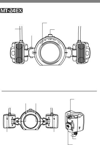
Nomenclature
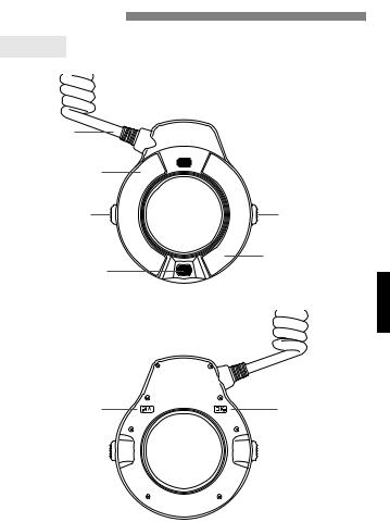
MR-14EX
Connecting
cord
Flash tube B (p.21)
Release button (p.12)
Focusing lamp (p.8)
Flash unit
 Focusing lamp (p.8)
Release button (p.12)
Flash tube A (p.21)
Flash Unit Rear
<h> Indicator |
<i> Indicator |
(p.21) |
(p.21) |
5
|
Flash Unit |
||
|
|
Hood mount (p.16) |
|
Connecting |
Rotate button |
Release button |
|
cord |
|||
(p.13) |
(p.12, 13) |
||
Focusing |
|||
|
|
||
lamp (p.8) |
|
|
|
|
|
|
|
|
|
|
|
|
|
|
|
|
|
|
|
|
|
|
|
|
|
|
|
|
|
|
|
|
|
|
|
|
|
|
|
|
|
|
|
|
|
|
|
|
|
|
|
|
|
|
|
|
|
|
|
|
|
|
|
|
|
|
|
|
|
|
|
|
|
|
|
|
|
|
|
|
|
|
|
|
|
|
|
|
|
|
|
|
|
|
|
|
|
|
|
|
|
|
|
Flash head B |
|
|
|
|
|
|
|
|
|
|
|
|
|
|
|
Flash head A |
|||
|
|
|
|
|
|
|
|
|
|
|
|
|
|
|
|||||
|
|
|
|
|
|
|
|
|
|
|
|
|
|
|
|||||
|
|
|
|
|
|
|
|
|
|
|
|
|
|
|
|||||
(p.21) |
|
|
|
|
|
|
|
|
(p.21) |
||||||||||
Flash head mount |
|
|
|
|
|
|
|
Mount ring (p.12, 13) |
|||||||||||
|
|
|
|
|
|
|
|||||||||||||
(p.12, 13) |
|
|
|
|
|
|
|
|
|
|
|||||||||
Standard position index |
|
|
|
|
Filter mounting thread (p.15) |
||||||||||||||
|
|
|
|
||||||||||||||||
(p.13) (Vertical angle) |
|
|
|
(58mm dia.) |
|||||||||||||||
Flash Unit Rear
Release levers
Flash Unit Side & Bottom
 Standard position index (Horizontal angle)
  Angle setting scale (p.13, 14)
<j> Indicator |
<k> Indicator |
|
(p.21) |
(p.21) |
Mounting foot (p.12) |
|
|
|
|
|
Tripod socket |
6
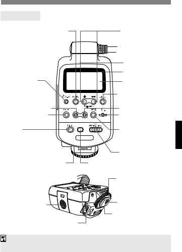
Control Unit
<D> Flash mode button |
<F> High-speed sync |
(p.18, 27, 33) |
(FP flash) button (p.26) |
|
<r> Shutter curtain |
|
synchronization button |
|
(p.26) |
*<B> LCD panel illumination button (p.8) <C> Custom Function setting button (p.28)
<b> button
<d> Focusing lamp button (p.8)
<J>
Pilot lamp (p.18)
Test firing button (p.18)
*<h> Plus button |
*<i> Minus button |
LCD panel (p.8) |
*<a> Select/Set |
button |
<c> button |
<e> Channel button |
(p.33) |
<f> Flash ratio/ |
Flash tube/head select |
button (p.21, 27, 33) |
|
Power switch (p.18) |
Locking ring (p.11) |
Flash exposure confirmation lamp (p.18) |
|
Mounting foot (p.11) |
Battery compartment |
Contacts |
|
|
cover (p.10) |
Locking pin (p.11) |
|
|
External power source socket |
|
Asterisked buttons have functions which remain active for 8 sec. after you press and let go of the button. The <B> illumination lasts for 12 sec.
7
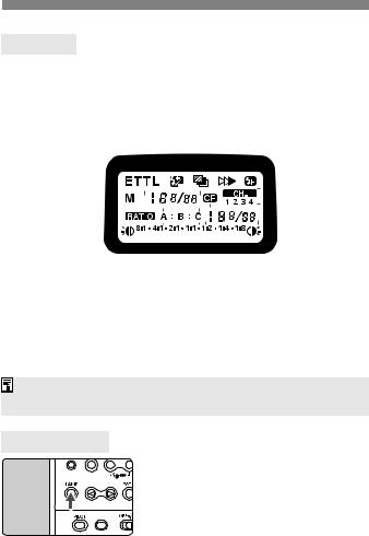
LCD Panel
Flash exposure compensation amount |
|
|
|
<g> FEB |
||||||||||||||||||||||||||||||||
FEB compensation amount |
|
|
|
|
|
|
|
|
|
|
|
|
||||||||||||||||||||||||
Manual flash output level |
|
|
|
|
|
|
|
<r> Second-curtain sync |
||||||||||||||||||||||||||||
<f> Flash exposure |
|
|
|
|
|
|
|
|
|
|
|
|
|
|
||||||||||||||||||||||
|
|
|
|
|
|
|
|
|
|
|
|
|
|
|||||||||||||||||||||||
|
|
|
|
|
|
|
|
|
|
|
|
|
|
|
|
|||||||||||||||||||||
compensation |
|
|
|
|
|
|
|
|
|
|
|
<c> High-speed sync |
||||||||||||||||||||||||
*<a/b> |
|
|
|
|
|
|
|
|
|
|
|
|
|
|
|
|
|
|
|
|
|
|
|
|
|
|
|
|
|
|
|
|
||||
|
|
|
|
|
|
|
|
|
|
|
|
|
|
|
|
|
|
|
|
|
|
|
|
(FP flash) |
||||||||||||
E-TTL (II)/TTL |
|
|
|
|
|
|
|
|
|
|
|
|
|
|
|
|
|
|
||||||||||||||||||
autoflash |
|
|
|
|
|
|
|
|
|
|
|
|
|
|
|
|
|
|
||||||||||||||||||
<q> Manual Flash |
|
|
|
|
|
|
|
|
|
|
|
|
|
|
|
|
|
|
|
|
|
|
|
|
<w> |
|||||||||||
Flash tube/head ID |
|
|
|
|
|
|
|
|
|
|
|
|
|
|
|
|
|
|
|
|
|
|
|
|
|
|
|
|
|
|
|
|
|
|
|
|
|
|
|
|
|
|
|
|
|
|
|
|
|
|
|
|
|
|
|
|
|
|
|
|
|
|
|
|
|
|
|
|
|
|
|
||
|
|
|
|
|
|
|
|
|
|
|
|
|
|
|
|
|
|
|
|
|
|
|
|
|
|
|
|
|
|
|
|
|
||||
|
|
|
|
|
|
|
|
|
|
|
|
|
|
|
|
|
|
|
|
|
|
|
|
|
|
Channel |
||||||||||
(A, B)/Slave ID (C) |
|
|
|
|
|
|
|
|
|
|
|
|
|
|
|
|
|
|
|
|
|
|
|
|
|
|
|
|
|
<l> |
||||||
|
|
|
|
|
|
|
|
|
|
|
|
|
|
|
|
|
|
|
|
|
|
|
|
|
|
|
|
|
|
|
|
|
|
|
|
|
|
|
|
|
|
|
|
|
|
|
|
|
|
|
|
|
|
|
|
|
|
|
|
|
|
|
|
|
|
|
|
|
|
|
|
|
|
<y> Flash ratio |
|
|
|
|
|
|
|
|
|
|
|
|
|
|
|
|
|
|
|
|
|
|
|
|
|
|
|
Custom Function |
||||||||
|
|
|
|
|
|
|
|
|
|
|
|
|
|
|
|
|
|
|
|
|
|
|
|
|
|
|
|
|
||||||||
<m> Flash tube/head |
|
|
|
|
|
|
|
|
|
|
|
|
|
|
|
|
|
<n> Flash tube/head |
||||||||||||||||||
A firing |
|
|
|
|
|
|
|
|
|
|
|
|
|
|
B firing |
|||||||||||||||||||||
Flash ratio scale |
|
|
|
|
|
|
|
|
|
FEB status |
||||||||||||||||||||||||||
|
|
|
|
|
|
|
|
|
||||||||||||||||||||||||||||
|
|
|
|
|
|
|
|
|
||||||||||||||||||||||||||||
Manual flash output scale |
|
|
|
|
|
|
|
|
|
|
Slave C flash exposure |
|||||||||||||||||||||||||
|
|
|
|
|
|
compensation amount |
||||||||||||||||||||||||||||||
|
|
|
|
|
|
|||||||||||||||||||||||||||||||
for A, B, and C |
|
|
|
Manual flash output for A, B, and C |
||||||||||||||||||||||||||||||||
|
|
|
|
|
|
|
|
|
|
Flash ratio |
|
|
|
|
Custom Function No. |
|||||||||||||||||||||
|
|
|
|
|
|
|
|
|
|
|
|
|
|
|||||||||||||||||||||||
To illuminate the LCD panel, press the <B> button.
The items actually displayed depend on the current settings.
* <a> will be displayed on the LCD panel even if the camera is compatible with E-TTL II.
Focusing Lamp
Pressing the <d> button turns on the focusing lamp for about 20 sec. to assist focusing in low light. Press the <d> button again to turn off the focusing lamp. Note that if you take the picture while the focusing lamp is lit, underexposure may result.
8
Before You Start
Installing the Batteries .......................................... |
10 |
Attaching the Control Unit...................................... |
11 |
Attaching the Flash Unit ....................................... |
12 |
Setting the Flash Unit............................ |
13 |
 To prevent the flash tube/head from deteriorating due to excessive heat, do not fire the flash continuously more than 20 times. After firing the flash continuously for 20 times, let the MR- 14EX/MT-24EX rest for 10 min. or longer. During continuous manual flash firing, allow the MR-14EX/MT-24EX to rest after the firing times indicated below.
Flash output |
1/1 |
|
1/2 |
1/4 |
|
1/8 |
1/16 |
1/32 |
1/64 |
Firing times |
15 |
|
20 |
|
40 |
|
|||
|
|
|
|
|
|
|
|
|
|
9
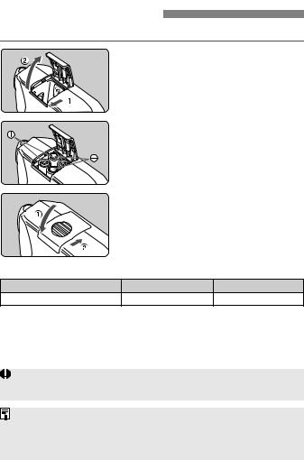
Installing the Batteries
Use four size-AA/LR6 batteries.
1 |
Open the cover. |
|
|
Slide the battery compartment cover |
|
|
as shown by the arrow, then flip up |
|
|
the edge. |
|
2 Insert the batteries. |
||
|
Make sure the + and - battery |
|
|
contacts are properly oriented as |
|
|
shown in the compartment. |
|
3 Close the cover. |
|
|
|
Push down the cover and slide it |
|
|
back. |
|
Recycling Time and Flash Count |
|
|
Battery Type |
Recycling Time |
Flash Count |
Size-AA/LR6 alkaline batteries |
Approx. 0.1 - 7 sec. |
Approx. 120 - 800 |
Based on a new set of batteries and Canon’s testing standards.
The figures are the same for both flash tubes/heads firing or single tube/head firing.
This applies to both the MR-14EX and MT-24EX.
Use a new set of four batteries of the same brand. When replacing the batteries, replace all four at one time.
Using size-AA batteries other than the alkaline type (LR6) may cause improper battery contact due to the irregular shape of the battery contacts.
Size-AA Ni-MH (HR6) or lithium (FR6) batteries can also be used.
10
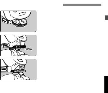
Attaching the Control Unit 
1
2
Loosen the locking ring.
Turn the locking ring as shown by the arrow to loosen it.
Attach the control unit.
Slip the control unit’s mounting foot into the camera’s hot shoe all the way.
3 Tighten the locking ring.
Turn the locking ring as shown by the arrow. The locking pin will then protrude from the mounting foot.
To detach the control unit, loosen the locking ring until the locking pin retracts, then detach the control unit.
11
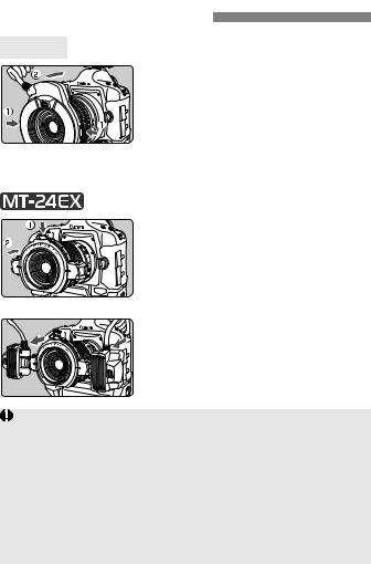
Attaching the Flash Unit 
MR-14EX
Hold down the release buttons
and attach the flash unit to the
front of the lens.
Make sure the flash unit is securely
attached.
The flash unit can be rotated.
To detach the flash unit, follow the above procedure in reverse.
1 Hold down the release button and
attach the mount ring to the front
of the lens.
Position the release button toward the top.
Make sure the mount ring is securely
attached.
2 Attach flash heads A and B to
flash head mounts.
Push it in until it clicks in place.
To detach the flash heads, press the release lever (p.6).
To EF100mm f/2.8L Macro IS USM Users
Macro Lite Adapter 67 (optional) is required. Screw on the adapter onto the lens filter thread, then attach the flash unit.
To EF180mm f/3.5L Macro USM Users
Macro Lite Adapter 72C (optional) is required. Screw on the adapter onto the lens filter thread, then attach the flash unit.
To rotate the mount ring, be sure to first hold down the release button. If the Macro Lite Adapter 72C screwed onto the EF180mm f/3.5L Macro USM lens filter thread becomes stuck and cannot be unscrewed, without pressing the release button, turn the ring against the lens in the direction you would to detach the Adapter.
12
 Setting the Flash Unit
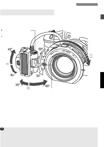
Adjustable Range of Flash Unit
The MT-24EX’s flash unit can be adjusted within the range shown below to match the lens and subject.
Standard position index (Horizontal angle) Angle setting scale
Standard position index (Vertical angle)
1This can be rotated. Be sure to hold down the release button when rotating the mount ring. After rotating it to the desired position, release the release button.
2Hold down the rotate button and turn the flash head mount. The flash head can be moved directly at 3 and 4.
Do not adjust the flash head angle beyond the adjustable range. Doing so may cause the flash head to detach and fall from the flash head mount.
The adjustable range may be further limited depending on the camera and lens.
13

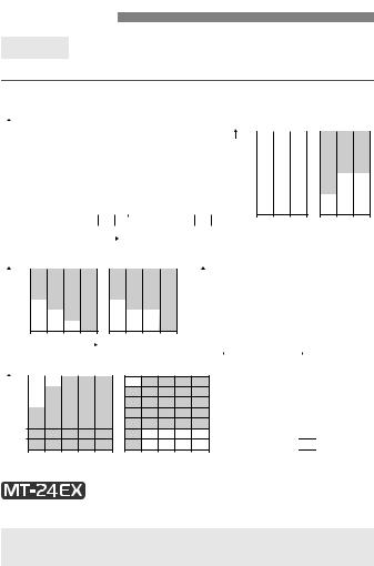
Flash Setting Guide
This is a general guide to setting the flash angle for various magnifications with a macro lens. Refer to the angle scale (15° increments) on the side of the flash head and set the same angle for both flash heads A and B. The angle specifications in the table below indicate the inner angle relative to the flash head’s standard position index (horizontal).
Lens |
Magnification |
Flash Head Inner Angle |
|||||
60° |
45° |
30° |
15° |
0° |
|||
|
|
||||||
|
1:2 |
|
z |
z |
|
|
|
|
1:2.5 - 1:3 |
|
|
z |
|
|
|
EF50mm f/2.5 Compact |
1:4 |
|
|
z |
z |
|
|
Macro |
1:5 - 1:6 |
|
|
|
z |
|
|
|
1:8 |
|
|
|
z |
z |
|
|
1:10 |
|
|
|
|
z |
|
EF50mm f/2.5 Compact |
1:1 |
|
z |
|
|
|
|
1:1.2 |
|
z |
z |
|
|
||
Macro |
|
|
|
||||
1:1.5 - 1:2 |
|
|
z |
|
|
||
+Life-Size Converter EF |
|
|
|
|
|||
1:4 |
|
|
|
z |
|
||
|
|
|
|
|
|||
EF100mm f/2.8L Macro IS |
1:1 - 1:1.5 |
|
|
z |
|
|
|
1:2 |
|
|
z |
z |
|
||
USM |
|
|
|
||||
1:3 |
|
|
|
z |
|
||
EF100mm f/2.8 Macro USM |
|
|
|
|
|||
1:5 |
|
|
|
|
z |
||
|
|
|
|
|
|||
|
1:1 |
|
z |
|
|
|
|
EF100mm f/2.8 Macro |
1:1.5 |
|
|
z |
|
|
|
1:2 |
|
|
z |
z |
|
||
|
1:2.5 - 1:3 |
|
|
|
z |
|
|
|
1:4 |
|
|
|
|
z |
|
EF180mm f/3.5L Macro |
1:1 |
|
|
z |
z |
|
|
1:1.2 - 1:1.5 |
|
|
|
z |
|
||
USM |
|
|
|
|
|||
1:2 - 1:10 |
|
|
|
|
z |
||
|
|
|
|
|
|||
MP-E65mm f/2.8 1-5x Macro |
5x - 2x |
z |
|
|
|
|
|
Photo |
1x |
|
z |
|
|
|
|
|
1:1 - 1:1.5 |
|
z |
|
|
|
|
EF-S60mm f/2.8 Macro |
1:2 |
|
|
z |
|
|
|
USM |
1:3 |
|
|
z |
z |
|
|
|
1:5 |
|
|
|
z |
|
|
14

Filter Compatibility
MR-14EX
EF50mm f/2.5 Compact Macro |
A filter can be attached directly to the lens. |
|
EF100mm f/2.8 Macro |
|
|
EF-S60mm f/2.8 Macro USM |
|
|
EF100mm f/2.8 Macro USM |
A filter cannot be attached. |
|
MP-E65mm f/2.8 1-5x Macro Photo |
|
|
EF100mm f/2.8L Macro IS USM |
Cannot be used with a filter. |
|
EF180mm f/3.5L Macro USM |
|
|
|
|
|
|
A filter can be attached directly to the lens. |
|
EF50mm f/2.5 Compact Macro |
Note: Do not attach a 58mm filter to the |
|
mount ring’s filter mounting thread. It |
||
|
||
|
would obstruct the front of the lens. |
|
|
|
|
EF100mm f/2.8L Macro IS USM |
A 58mm filter can be attached to the |
|
EF100mm f/2.8 Macro USM |
mount ring’s filter mounting thread. |
|
EF100mm f/2.8 Macro |
|
|
EF180mm f/3.5L Macro USM |
|
|
EF-S60mm f/2.8 Macro USM |
|
|
MP-E65mm f/2.8 1-5x Macro Photo |
|
15

Hood Compatibility
MR-14EX
•If you want to use the dedicated hood (optional) with the MP-E65mm f/2.8 1-5x Macro Photo, first attach the hood, then attach the flash unit.
•A hood cannot be attached to any other lens.
•If you want to use the dedicated hood (optional) with the MP-E65mm f/2.8 1-5x Macro Photo, first attach the hood, then attach the mount ring. If a hood is attached, a 58mm filter cannot be attached to the filter mounting thread.
•With an EF100mm f/2.8 Macro USM, the ET-67 hood can be attached to the mount ring’s hood mount. Use ambient light for the picture. Using flash will result in darkened edges.
16

2
Flash Photography
Turning on the Power Switch................................ |
18 |
Fully Automatic Flash Shooting ............................ |
18 |
Automatic Flash in Each Shooting Mode.............. |
19 |
Flash Range ......................................................... |
20 |
mnSetting the Flash Ratio............................. |
21 |
7FE Lock ........................................................ |
23 |
fFlash Exposure Compensation ...................... |
24 |
gFEB ................................................................ |
25 |
cHigh-speed sync ............................................. |
26 |
rSecond-curtain sync ..................................... |
26 |
qManual Exposure ............................................ |
27 |
CSetting Custom Functions .......................... |
28 |
Custom Function Settings .................................... |
29 |
 Setting the correct exposure for closeup shots largely depends on the subject. It is best to bracket the exposure for the same subject. (p.24)
If the EOS camera has a initialize function for camera settings, initializing the camera settings will also initialize the flash settings (excluding Custom Function settings).
17
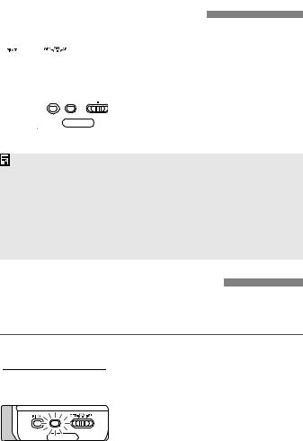
Turning on the Power Switch
 1
1
 2
2
Turn on the power switch.
Set the power switch to <K> or <g>.
X The flash recycling starts.
Check that the flash is ready.
The pilot lamp will light in red (fully charged) when the flash is ready.
XPressing the pilot lamp will fire a test flash.
To save battery power, the <g> Save Energy feature automatically turns off the MR-14EX/MT-24EX after 90 sec. of non-operation. To turn on the MR- 14EX/MT-24EX again, press the camera’s shutter button halfway.
A test firing cannot be fired while the camera’s operation timer 4or 0 is active.
The MR-14EX/MT-24EX’s settings will be retained in memory even after the power is turned off. To retain the MR-14EX/MT-24EX’s settings when you replace the batteries, replace the batteries within 1 minute after turning off the power.
Fully Automatic Flash Shooting
When the camera’s shooting mode is set to <V> (Program AE) or <U> (Full Auto), E-TTL II/E-TTL fully automatic flash photography will be enabled, making it as easy as normal AE shooting in the <V> or <U> mode.
 1
1  2
2
Set the MR-14EX/MT-24EX to <ETTL>.
Press the <D> button to display <a>.
Take the picture.
Focus the picture and check that the <Q> icon is lit in the viewfinder.
XIf a standard flash exposure was obtained, the flash exposure confirmation lamp will light for about 3 sec.
18
Automatic Flash in Each Shooting Mode 
Just set the camera’s shooting mode to <W> (aperture-priority AE) or <O> (manual exposure) to enable macro flash shooting with E-TTL II/ E-TTL autoflash.
<W> Aperture-priority AE
This mode is effective for controlling the depth of field or obtaining the standard exposure for both the subject and background. You set the aperture as desired, and the shutter speed is set automatically (30 sec. - 1/X* sec.) to obtain the standard background exposure. Based on the set aperture, E-TTL II/E-TTL autoflash is used for the shot.
Since a slow shutter speed will be used for low-light scenes, using a tripod is recommended.
If the shutter speed display blinks, it means that the background exposure will be underexposed or overexposed. Adjust the aperture until the shutter speed display stops blinking.
<O> Manual exposure
Select this mode when you want to set both the shutter speed and aperture manually. Standard exposure of the main subject is obtained with the flash. The exposure of the background is obtained with the shutter speed (buLb, 30 sec. - 1/X* sec.) and aperture combination you set.
With <X> (shutter-priority AE), you set the shutter speed (30 sec. - 1/X* sec.) as desired, and the camera sets the aperture automatically. However, this mode is not recommended since you cannot set the aperture.
In the <Z> or <Y> mode, the result will be the same as shooting in the <V> mode.
* 1/X sec. is the respective camera’s maximum flash sync speed.
19
Flash Range
MR-14EX
The MR-14EX’s flash range is shown below.
EF50mm f/2.5 Compact Macro
|
32 |
|
|
|
|
ISO100 |
|
|
|
|
ISO400 |
||||||||
|
|
|
|
|
|
|
|
|
|
|
|
|
|
|
|
|
|
|
|
Aperture |
22 |
|
|
|
|
|
|
|
|
|
|
|
|
|
|
|
|
|
|
|
16 |
|
|
|
|
|
|
|
|
|
|
|
|
|
|
|
|
|
|
|
11 |
|
|
|
|
|
|
|
|
|
|
|
|
|
|
|
|
|
|
|
8 |
|
|
|
|
|
|
|
|
|
|
|
|
|
|
|
|
|
|
|
5.6 |
|
|
|
|
|
|
|
|
|
|
|
|
|
|
|
|
|
|
|
4 |
|
|
|
|
|
|
|
|
|
|
|
|
|
|
|
|
|
|
|
2.8 |
|
|
|
|
|
|
|
|
|
|
|
|
|
|
|
|
|
|
|
2.5 |
|
|
|
|
|
|
|
|
|
|
|
|
|
|
|
|
|
|
|
|
|
|
|
|
|
|
|
|
|
|
|
|
|
|
|
|
|
|
|
0.13 |
0.13 |
|||||||||||||||||
|
0.2 |
0.3 |
0.5 |
|
0.2 |
0.3 |
0.5 |
|
|||||||||||
+Life-Size Converter EF |
0.5 0.67 1 |
|
|
|
|
|
|
0.5 0.67 1 |
|||||||||||
|
|
|
|
|
|
Magnification |
|
|
|
|
|
|
|
|
|
||||
EF100mm f/2.8L Macro IS USM/ EF100mm f/2.8 Macro USM/ EF100mm f/2.8 Macro
|
32 |
|
ISO100 |
|
ISO400 |
|
|
|
|
|
|
Aperture |
22 |
|
|
|
|
|
16 |
|
|
|
|
|
11 |
|
|
|
|
|
8 |
|
|
|
|
|
5.6 |
|
|
|
|
|
4 |
|
|
|
|
|
2.8 |
|
|
|
|
|
|
|
|
|
|
0.33 0.5 0.7 1 0.33 0.5 0.7 1 Magnification
MP-E65mm f/2.8 1-5x Macro Photo
|
16 |
ISO100 |
|
ISO400 |
|
|
|
|
|
Aperture |
11 |
|
|
|
|
|
|
||
8 |
|
|
|
|
|
|
|
|
|
|
5.6 |
|
|
|
|
|
|
|
|
|
4 |
|
|
|
|
|
|
|
|
|
2.8 |
|
|
|
|
|
|
|
1 |
2 |
3 |
4 |
5 |
1 |
2 |
3 |
4 |
5 |
|
Magnification |
|
|
|
|
|
|
||
EF180mm f/3.5L Macro USM
32 |
ISO100 |
ISO400 |
|
|
|
22 |
|
|
|
|
|
Aperture |
|
|
16 |
|
|
11 |
|
|
|
|
|
8 |
|
|
|
|
5.6
3.5
0.1 0.2 0.3 0.5 0.7 1 0.1 0.2 0.3 0.5 0.7 Magnification
EF-S60mm f/2.8 Macro USM
|
32 |
|
|
ISO100 |
|
|
|
ISO400 |
|
||||||||
|
|
|
|
|
|
|
|
|
|
|
|
|
|
|
|
|
|
Aperture |
22 |
|
|
|
|
|
|
|
|
|
|
|
|
|
|
|
|
|
16 |
|
|
|
|
|
|
|
|
|
|
|
|
|
|
|
|
|
11 |
|
|
|
|
|
|
|
|
|
|
|
|
|
|
|
|
|
8 |
|
|
|
|
|
|
|
|
|
|
|
|
|
|
|
|
|
5.6 |
|
|
|
|
|
|
|
|
|
|
|
|
|
|
|
|
|
4 |
|
|
|
|
|
|
|
|
|
|
|
|
|
|
|
|
|
2.8 |
|
|
|
|
|
|
|
|
|
|
|
|
|
|
|
|
|
|
|
|
|
|
|
|
|
|
|
|
|
|
|
|
|
|
|
0.25 0.33 |
0.5 |
0.67 |
1 0.25 0.33 |
0.5 |
0.67 |
1 |
||||||||||
Magnification

 : Flash range
1
The MT-24EX’s flash range largely depends on the flash head’s position.
 When shooting at the closest focusing distance, stop down the aperture by 3 stops (ISO 100) from the maximum aperture.
20
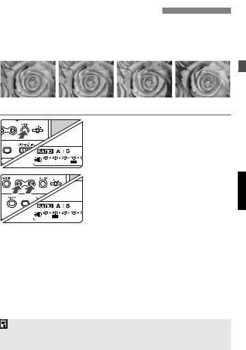
mnSetting the Flash Ratio 
You can adjust the flash ratio of flash tubes/heads A and B or fire only one of the flash tubes/heads. This can create shadows on the subject to give a more sculptural look. The flash ratio can be set in half-stop increments as follows: 1:8 - 1:1 - 8:1 (13 settings)
A:B = 1:1 |
A:B = 4:1 |
Only flash tube/head A Only flash tube/head B |
1
2
Select <yl>.
Press the <f> button to display <yl>.
Set the flash ratio.
Press <b> or <c> to select from 1:8 - 1:1 - 8:1. The extreme left or right setting will fire only one of the flash tubes/heads.
X<m>: Only <j> will be fired. <n>: Only <k> will be fired.
Since the exposure will be controlled automatically, there is no need to calculate the exposure.
If the flash mode is <q>, see page 27.
21
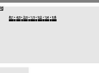
The value of the  bar in the flash ratio scale below is indicated in parentheses.
(5.6:1) (2.8:1) (1.4:1) (1:1.4) (1:2.8) (1:5.6)
In terms of aperture stops, the flash ratio range is equivalent to 3:1 - 1:1 - 1:3.
If the picture is taken while <y> is not displayed, flash tubes/heads A and B will fire at the same output.
Flash ratio control is not possible with the following cameras. You can fire both flash tubes/heads at the same output or fire only one of the flash tubes/heads.
EOS ELAN ll/ELAN ll E/50/50E, EOS REBEL G/500N, EOS IX, EOS IX Lite/IX7, EOS 3000/88, EOS REBEL 2000/300, EOS REBEL XS N/ REBEL G II/3000N/66
Modeling Flash
If the camera has a depth-of-field preview button, pressing it will fire the flash continuously for 1 sec. This is called the modeling flash. It enables you to see the shadow effects on the subject and the lighting balance. The modeling flash also works with a wireless, multi-Speedlite system.
22
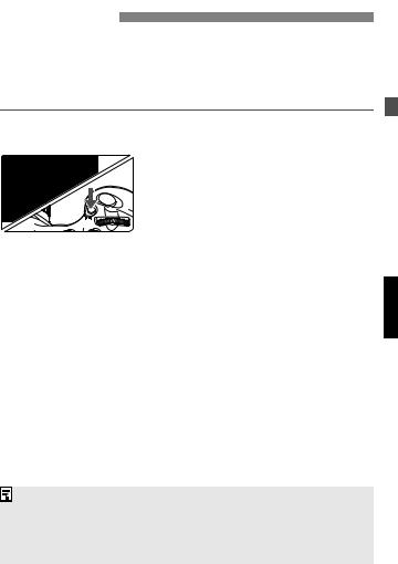
7FE Lock
FE (flash exposure) lock locks the correct flash exposure reading for any part of the scene.
With <a> displayed on the LCD panel, press the camera’s <7> button. If the camera does not have a <7> button, press the <P> button.
1
2
Focus the subject.
Press the <7> button. (3) Place the subject at the center of the viewfinder and press the <7> button.
XThe MR-14EX/MT-24EX will fire a preflash and the required flash output for the subject is retained in memory.
XThe FEL display will be shown in the viewfinder for 0.5 sec.
Each time you press the <7> button, a preflash is fired to update the FE lock reading.
If the subject is too far away and underexposure will result, the <Q> icon will blink in the viewfinder. Move closer to the subject and try the FE lock again.
If <a> is not displayed on the LCD panel, FE lock cannot be set. If the subject is too small, FE lock might not be very effective.
23

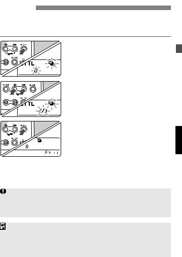
fFlash Exposure Compensation
In the same way as normal exposure compensation, you can set exposure compensation for flash. The flash exposure compensation amount can be set up to ±3 stops in 1/3-stop increments.
1 Select <f>.
Press the <a> button to display <f>.
X <f> and the flash exposure compensation amount will blink.
2Set the flash exposure compensation amount.
Press the <h> or <i> button to set the flash exposure compensation amount.
To cancel the flash exposure compensation amount, set it to “0”.
3Press the <a> button.
X The flash exposure compensation
amount will be set.
If the flash exposure compensation amount has been set by both the MR-14EX/MT-24EX and camera, the MR-14EX/MT-24EX’s flash exposure compensation amount will override the camera’s.
If the camera’s exposure setting increment is 1/2 stop, the flash exposure compensation will be set in 1/2-stop increments.
24
gFEB
The camera brackets the flash exposure automatically up to ±3 stops in 1/3-stop increments for three successive shots. This is called FEB (Flash Exposure Bracketing).
1 Select <g>.
Press the <a> button to display <g>.
X <g> and the bracketing amount will blink.
2Set the flash exposure bracketing amount.
Press the <h> or <i> button to set the bracketing amount.
3 Press the <a> button.
X FEB will be set.
For FEB, set the camera’s drive mode to single shooting. Be sure the flash is ready before shooting.
FEB cannot be used together with flash exposure compensation set with the camera.
After the three shots are taken, FEB will be cancelled automatically. FEB can be used together with FE lock or flash exposure compensation set with the MR-14EX/MT-24EX.
If the camera’s exposure setting increment is 1/2 stop, the FEB will be set in 1/2-stop increments.
25
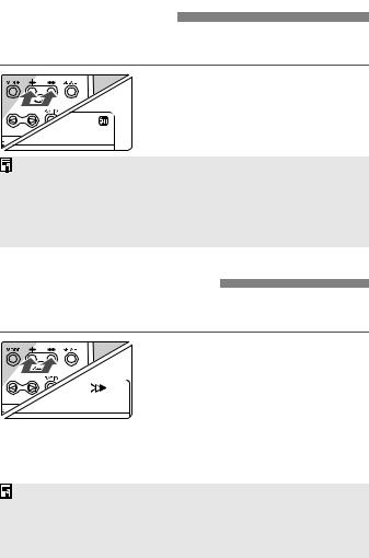
cHigh-speed sync
With high-speed sync (FP flash), the flash can synchronize with all shutter speeds.
Select <c>.
Press the <h> and <i> buttons simultaneously to display <c>.
In the viewfinder, check that the <F> icon is lit.
If the shutter speed is slower than the maximum flash sync speed, <F> will not be displayed in the viewfinder.
To return to normal flash, press the <h> and <i> buttons simultaneously to turn off <c>.
With high-speed sync, the faster the shutter speed, the shorter the flash range will become.
rSecond-curtain sync
With a slow shutter speed, you can create a light trail following the subject. The flash fires right before the shutter closes.
Select <r>.
Press the <h> and <i> buttons simultaneously to display <r>.
The camera’s “buLb” mode works well with second-curtain sync. To return to normal flash, press the <h> and <i> buttons simultaneously to turn off <r>.
With E-TTL II/E-TTL, two flashes will be fired even at slow shutter speeds. The first flash is the preflash.
26
qManual Exposure
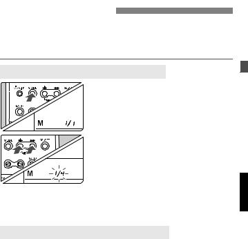
You can set the flash output manually from full output at 1/1 to 1/64 output in full-stop increments. The flash can be fired in one of three ways: 1. A and B fired at the same output, 2. A and B fired at a different output, 3. Only A or B is fired. You should first take a test shot to check the exposure.
Firing A and B at the Same Flash Output
1
2
Select <q>.
Press the <D> button to display <q>.
Set the flash output.
Press the <a> button.
XThe flash output blinks.
Press the <h> or <i> button to set the flash output.
XEach time you press the button, the flash output will increase/decrease by 1 stop. Press the <a> button.
XThe flash output is displayed.
Firing A and B at a Different Flash Output
For step 2 above, follow the procedure below to set a different flash output for A and B.
1
2
Press the <f> button to display <yl>.
Select the flash tube/head.
Press the <b> button to select <1>, and the <c> button to select <2>.
3 Set the flash output.
Press the <h> or <i> button to set the flash output. Pressing the <i> button to set the flash output to “--” will set only the other flash tube/head to fire.
XThe setting after 1/64 is “--”. The flash tube/head whose flash output has been set to “--” will not fire.
27
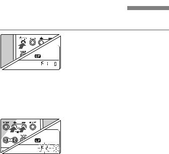
CSetting Custom Functions 
Custom Functions enable you to customize MR-14EX/MT-24EX features to suit your picture-taking preferences.
1 Display the <l> icon.
Hold down the <A> button for 2 sec. or more.
2 Select the Custom Function No.
Press the <a> button, and the Custom Function number and setting number will blink. Press the <a> button to select the Custom Function number.
3 Set the setting number.
Press the <h> or <i> button to select “0” or “1”, then press the <a> button.
X The blinking will stop and the setting will take effect.
XPressing the <A> button or <D> button will return the camera to shooting ready.
28
 Loading...