


 Loading...
SERVICE
MANUAL
REVISION 0
JAN. 1999 |
FY8-13FD-000 |
COPYRIGHT © 1999 CANON INC. |
CANON GP605/GP605V REV.0 JAN. 1999 PRINTED IN JAPAN (IMPRIME AU JAPON) |

IMPORTANT
THE INFORMATION CONTAINED HEREIN IS PUBLISHED BY CANON, INC., JAPAN. SPECIFICATIONS AND OTHER INFORMATION CONTAINED HEREIN MAY DIFFER SLIGHTLY FROM ACTUAL MACHINE VALUES OR THOSE FOUND IN ADVERTISING AND OTHER PRINTED MATTER.
ANY QUESTIONS REGARDING INFORMATION CONTAINED HEREIN SHOULD BE DIRECTED TO THE COPIER SERVICE DEPARTMENT OF THE COMPANY.
COPYRIGHT  1999 CANON INC.
Printed in Japan
Imprimé au Japon
Use of this manual should be strictly
supervised to avoid disclosure of confi-
dential information.
Prepared by
OFFICE IMAGING PRODUCTS TECHNICAL SUPPORT DEPARTMENT 3
OFFICE IMAGING PRODUCTS TECHNICAL SUPPORT DIVISION
CANON INC.
5-1, Hakusan 7-chome, Toride, Ibaraki, 302-8501 Japan
COPYRIGHT © 1999 CANON INC. |
CANON GP605/GP605V REV.0 JAN. 1999 PRINTED IN JAPAN (IMPRIME AU JAPON) |


INTRODUCTION
This Service Manual contains basic data and figures on the GP605/605V needed to service the machine in the field. The copier is a multifunction machine designed to provide printer functions as an option.
This Service Manual consists of the following chapters; refer to the Copier Basic Series as necessary for common technologies:
CHAPTER 1 General Description introduces the copier’s features and specifications, shows how to operate the printer unit, and explains how copies are made.
CHAPTER 2 Basic Operation provides outlines of the steps used to generate copies.
CHAPTER 3 Exposure System discusses the principles of operation used for the mechanical/electrical operations of the copier’s exposure system. It also explains the timing at which the various units involved are operated, and shows how they may be disassembled/assembled and adjusted.
CHAPTER 4 Image Processing System discusses the principles of operation used for the mechanical/electrical operations of the copier’s image processing system. It also explains the timing at which the various units involved are operated, and shows how they may be disassembled/assembled and adjusted.
CHAPTER 5 Laser Exposure System discusses the principles of operation used for the mechanical/electrical operations of the copier’s laser exposure system. It also explains the timing at which the various units involved are operated, and shows how they may be disassembled/assembled and adjusted.
CHAPTER 6 Image Formation System discusses the principles of how images are formed. It also explains the timing at which the various units involved in image formation are operated, and shows how they may be disassembled/assembled and adjusted.
CHAPTER 7 Pick-Up/Feeding System discusses the principles of how the printer unit picks up and moves paper inside it. It also explains the timing at which the various units involved are operated, and shows how they may be disassembled/assembled and adjusted.
CHAPTER 8 Fixing System discusses the principles of how the printer unit fuses toner images to paper. It also explains the timing at which the various units involved are operated, and shows how they may be disassembled/assembled and adjusted.
CHAPTER 9 Externals/Auxiliary Mechanisms shows the copier’s external parts, and explains the principles used for the copier’s various control mechanisms in view of the functions of electrical and mechanical units and in relation to their timing of operation. It also shows how these units may be disassembled/assembled and adjusted.
CHAPTER 10 Side Paper Deck discusses the principles of operation used for the series of operations between pickup and delivery performed by the paper deck. It also explains the timing at which the various units involved are operated, and shows how they may be disassembled/assembled and adjusted.
CHAPTER 11 Installation introduces requirements for the site of installation, and shows how the printer unit may be installed using step-by-step instructions.
COPYRIGHT © 1999 CANON INC. |
CANON GP605/605V REV.0 JAN. 1999 PRINTED IN JAPAN (IMPRIME AU JAPON) |
i |
CHAPTER 12 Maintenance and Servicing provides tables of periodically replaced parts and consumables/durables and scheduled servicing charts.
CHAPTER 13 Troubleshooting provides tables of maintenance/inspection, standards/ adjustments, and problem identification (image fault/malfunction).
APPENDIX contains a general timing chart and general circuit diagrams.
The descriptions in this Service Manual are subject to change without notice for product improvement or other purposes, and major changes will be communicated in the form of Service Information bulletins.
All service persons are expected to have a good understanding of the contents of this Service Manual and all relevant Service Information bulletins and be able to identify and isolate faults in the machine.
This Service Manual is prepared so that a full understanding may be attained when it is used side by side with the separately available Copier Basic Series. Refer to the appropriate section of the document when prompted as follows:
EX.
 Volume 3>Chapter 6>VI.A.2. "Cleaning the Charging Wire"
The Copier Basic Series is a combination of descriptions on the existing technologies used in Canon copiers. It consists of the following seven volumes, and is intended to supplement the contents of Service Manuals:
Volume I |
Introduction Fundamental Technology |
Volume II |
Applied Technology Analog Copiers |
Volume III |
Applied Technology Digital Copiers |
Volume IV |
Applied Technology Color Copiers |
Volume V |
Applied Technology Accessories |
Volume VI |
Applied Technology Controllers |
Volume VII |
Appendix Product Line and Accessories |
ii
COPYRIGHT © 1999 CANON INC. |
CANON GP605/605V REV.0 JAN . 1999 PRINTED IN JAPAN (IMPRIME AU JAPON) |
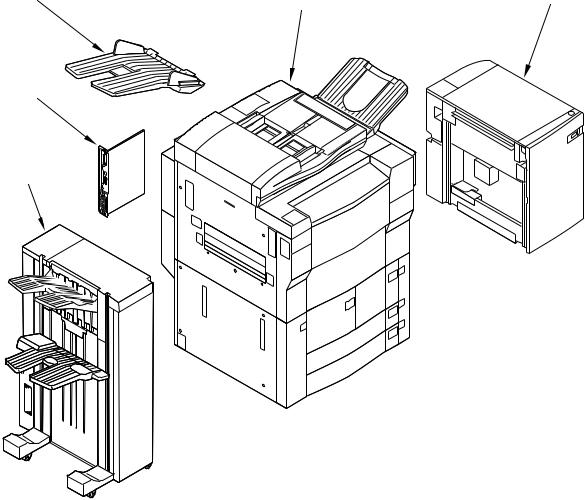
System Configuration
The GP605/605V may be configured as follows:
[3] |
[4] |
[5] |
[2]
[1]
[1]Finisher-D1
[2]Printer Board
[3]Copy tray
[4]GP605/605V
[5]Side Paper Deck-C1
Figure 1
COPYRIGHT © 1999 CANON INC. |
CANON GP605/605V REV.0 JAN. 1999 PRINTED IN JAPAN (IMPRIME AU JAPON) |
iii |
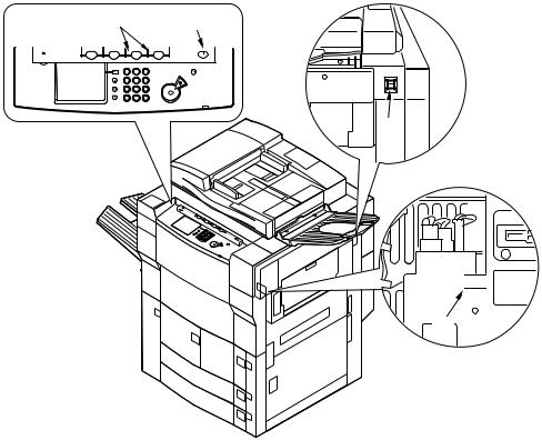
When Turning Off the Main Power Switch
Be sure to turn off the main power switch, and disconnect the power plug before starting disassembly/assembly work with the following in mind:
1.When you turn off the main power switch for adding printer functions, any data being processed at the time may be lost. Check to make sure that the data lamp on the control panel is off before operating the main power switch.
After turning off the main power switch, disconnect the communication cable from the printer board so that data will not be accepted during work.
2.Do not turn off the main power switch when downloading is taking place. Otherwise, the machine may stop operating.
3.Some units remain powered even when the control panel power switch is turned off. Be sure to turn off the main power switch, and disconnect the power plug before starting disassembly/assembly work.
(If the heater switch is on, the cassette heater and the drum heater remain powered even when the main power switch is turned off.)
4.Not all power will be removed even when the front door is opened if both the control panel power switch and the main power switch are on.
[1][2]
Copying |
COPY A |
Error |
Copying |
COPY B |
Error |
Data |
MAIL BOX Error |
Data |
OPTIONS Error |
ON/OFF |
1 2 3
4 5 6
7 8 9
ID 0 C
[3]
OFF  ON
ON
[4]
[1]Data lamp
[2]Power switch
[3]Main power switch
[4]Heater switch
Figure 2 Arrangement of the Switches
iv
COPYRIGHT © 1999 CANON INC. |
CANON GP605/605V REV.0 JAN . 1999 PRINTED IN JAPAN (IMPRIME AU JAPON) |

CONTENTS
CHAPTER 1 GENERAL DESCRIPTION
I. |
FEATURES ................................. |
1-1 |
||
II. |
SPECIFICATIONS ...................... |
1-2 |
||
|
A. |
Copier .................................... |
1-2 |
|
|
|
1. |
Type .................................. |
1-2 |
|
|
2. |
System .............................. |
1-2 |
|
|
3. |
Performance ..................... |
1-3 |
|
|
4. |
Others ............................... |
1-7 |
|
B. |
Side Paper Deck-C1 ............ |
1-10 |
|
III. NAMES OF PARTS .................. |
1-11 |
|||
|
A. |
External View ....................... |
1-11 |
|
|
B. |
Cross Section ...................... |
1-14 |
|
IV. OPERATING THE COPIER ...... |
1-16 |
|||
|
A. Turning on the Power Switch |
|||
|
|
............................................. |
|
1-16 |
B. |
Control Panel ....................... |
1-17 |
C. |
Extension Mode ................... |
1-18 |
D. |
User Mode ........................... |
1-19 |
V. ROUTINE MAINTENANCE BY THE |
||
USER ........................................ |
1-21 |
|
VI. SAFETY .................................... |
1-22 |
|
A. Safety of Laser Light ............ |
1-22 |
|
B. |
CDRH Regulations .............. |
1-23 |
C. Handling the Laser Assembly |
||
|
............................................. |
1-24 |
D. |
Safety of Toner .................... |
1-28 |
VII. IMAGE FORMATION ................ |
1-29 |
|
A. |
Outline .................................. |
1-29 |
CHAPTER 2 BASIC OPERATIONS
I. BASIC OPERATIONS ................. |
2-1 |
1. |
Basic Sequence of Operations |
|||
A. |
Functional Construction ......... |
2-1 |
|
(power-on) ........................ |
2-5 |
|
B. |
Electrical Circuitry .................. |
2-2 |
D. Controlling the Main Motor (M1) |
|||
|
1. |
Outline .............................. |
2-2 |
............................................... |
|
2-6 |
|
2. |
MFC PCB .......................... |
2-2 |
1. |
Outline .............................. |
2-6 |
|
3. |
Image Processor PCB ...... |
2-2 |
E. Inputs to and Outputs from the |
||
|
4. |
DC Controller PCB ........... |
2-3 |
Major PCBs ............................ |
2-7 |
|
|
5. |
Control panel CPU PCB ... |
2-3 |
1. |
Wiring Diagram of Major |
|
|
6. |
Original Orientation Detection |
|
PCBs ................................. |
2-7 |
|
|
|
PCB................................... |
2-3 |
2. |
Inputs to the DC Controller |
|
|
7. |
Image Server .................... |
2-3 |
|
PCB................................... |
2-8 |
C. |
Basic Sequence of Operations |
3. |
Outputs from the DC |
|
||
|
............................................... |
|
2-5 |
|
Controller PCB ................ |
2-14 |
CHAPTER 3 ORIGINAL EXPOSURE SYSTEM
I. OPERATIONS ............................ |
3-1 |
A. Outline .................................... |
3-1 |
B. Basic Sequence of Operations
............................................... 3-3
C. Changing the Reproduction Ratio
............................................... 3-4
II. SCANNER DRIVE SYSTEM ...... |
3-5 |
A. Outline .................................... |
3-5 |
B. Controlling the Scanner Motor |
3-6 |
............................................... |
|
III. CONTROLLING THE SCANNING |
|
LAMP .......................................... |
3-8 |
COPYRIGHT © 1999 CANON INC. |
CANON GP605/605V REV.0 JAN. 1999 PRINTED IN JAPAN (IMPRIME AU JAPON) |
v |

A. |
Outline .................................... |
3-8 |
B. Controlling the Temperature by a |
||
|
Fluorescent Lamp Heater .... |
3-10 |
C. Controlling Pre-Heat Voltage |
3-10 |
|
|
............................................. |
|
D. |
Initial Activation .................... |
3-11 |
E. |
Detecting an Error ................ |
3-12 |
IV. DETECTING THE ORIGINAL SIZE |
||
.................................................. |
|
3-14 |
A. |
Outline .................................. |
3-14 |
B. Detection by Original Sensors |
||
|
............................................. |
3-14 |
C. Detection by the Feeder ...... |
3-14 |
|
V. DISASSEMBLY/ASSEMBLY .... |
3-15 |
|
A. |
No. 1 Mirror Mount ............... |
3-16 |
1.Removing the Scanning Lamp/Scanning Lamp Heater
........................................ 3-16
2.Points to Note When
Replacing the Scanning Lamp
........................................ 3-19
3.After Replacing the Scanning
Lamp ............................... |
3-19 |
B. Scanner Drive Assembly ..... |
3-20 |
1.Removing the Scanner Motor
........................................ |
3-20 |
2. Scanner Drive Cable ...... |
3-21 |
C. PCBs .................................... |
3-28 |
1.Removing the Light Intensity
Control PCB .................... |
3-28 |
2.Removing the Inverter PCB
........................................ |
3-29 |
D. Others .................................. |
3-31 |
1.Removing the Original Size
Sensor (1/2) .................... |
3-31 |
2.Removing the Original Size
Sensor (3/4) .................... |
3-32 |
3.Removing the Scanner Home
Position Sensor .............. |
3-33 |
4.Removing the Copyboard
Glass ............................... |
3-33 |
5.Removing the Image Leading
Edge Sensor ................... |
3-34 |
6.Removing the Standard White
Plate ................................ |
3-35 |
7.After Replacing the Standard
White Plate ..................... |
3-36 |
CHAPTER 4 IMAGE PROCESSING SYSTEM
I. OUTLINE..................................... |
4-1 |
II.ANALOG IMAGE PROCESSING 4-4
A. |
Outline .................................... |
4-4 |
|
III. DIGITAL IMAGE PROCESSING 4-6 |
|||
A. |
Outline .................................... |
4-6 |
|
B. |
Image Procesing Functional |
|
|
|
Block ...................................... |
4-7 |
|
C. |
Shading Correction ................ |
4-9 |
|
D. |
Line Conversion ................... |
4-10 |
|
E. |
Editing .................................. |
4-11 |
|
F. |
Density Processing .............. |
4-12 |
|
|
1. |
Outline ............................ |
4-12 |
|
2. |
Density Adjustment during |
|
|
|
Printing ............................ |
4-14 |
G. |
Binary Processing ................ |
4-15 |
|
|
1. |
Dither Screen Method..... |
4-15 |
2.Random Error Diffusion (R-
ED) Method ..................... |
4-16 |
H. Image Memory ..................... |
4-17 |
I.Detecting the Orientation of
|
Originals ............................... |
4-19 |
J. |
Black Pixel Count ................. |
4-20 |
IV. DISASSEMBLY/ASSEMBLY .... |
4-21 |
|
A. |
CCD PCB ............................. |
4-22 |
1.Removing the CCD PCB
........................................ 4-22
2.After Replacing the CCD Unit
........................................ |
4-23 |
B. Image Processor PCB ......... |
4-24 |
1.Removing the Image
Processor PCB ............... |
4-24 |
2.After Replacing the Image
Processor PCB ............... |
4-25 |
C. Hard Disk (image server) ..... |
4-26 |
1.Removing the Hard Disk
(image server)................. |
4-26 |
2.After Replacing the Hard Disk
(image server)................. |
4-26 |
D. Others .................................. |
4-27 |
1.Removing the System
Motherboard ................... |
4-27 |
2.Removing the Memory Board
........................................ 4-28
3.Removing the Various Printer
Boards ............................ |
4-28 |
4.Removing the Original
Detection PCB ................ |
4-29 |
vi
COPYRIGHT © 1999 CANON INC. |
CANON GP605/605V REV.0 JAN. 1999 PRINTED IN JAPAN (IMPRIME AU JAPON) |
CHAPTER 5 LASER EXPOSURE SYSTEM
I. |
OPERATIONS ............................ |
5-1 |
IV. Controlling the Laser Scanner Motor |
||||
|
A. |
Outline .................................... |
5-1 |
.................................................. |
|
|
5-12 |
|
B. Basic Sequence of Operations |
A. |
Outline .................................. |
5-12 |
|||
|
|
(laser exposure system) ........ |
5-4 |
V. DISASSEMBLY/ASSEMBLY .... |
5-13 |
||
II. GENERATING THE BD SIGNAL 5-5 |
A. |
Laser Unit............................. |
5-14 |
||||
|
A. |
Outline .................................... |
5-5 |
|
1. |
Removing the Laser Unit |
|
|
B. Flow of the BD Signal ............ |
5-5 |
|
|
........................................ |
5-14 |
|
III. |
LASER DRIVER PCB ................. |
5-7 |
|
2. |
After Replacing the Laser Unit |
||
|
A. |
Outline .................................... |
5-7 |
|
|
........................................ |
5-15 |
|
B. |
Controlling the Laser Activation |
B. |
BD Unit ................................. |
5-16 |
||
|
|
............................................... |
5-8 |
|
1. |
Removing the BD Unit .... |
5-16 |
|
C. Controlling the Laser Intensity |
|
|
|
|
||
|
|
............................................. |
5-10 |
|
|
|
|
CHAPTER 6 IMAGE FORMATION SYSTEM
I . PROCESSES .............................. |
6-1 |
|
A. |
Outline .................................... |
6-1 |
B. Basic Sequence of Operations |
||
|
(image formation) ................... |
6-3 |
II . POTENTIAL CONTROL ............. |
6-5 |
|
A. |
Outline .................................... |
6-5 |
B. Determining the Optimum Grid |
||
|
Bias ........................................ |
6-8 |
C.Grid Bias Corrective Control .. 6-8
D.Determining the Optimum Laser
Output .................................... |
6-9 |
E. Laser Output Corrective control
............................................... 6-9
F.Determining the Optimum
Developing Bias ................... |
6-10 |
G. Potential Control for |
|
Transparency Mode ............. |
6-11 |
H. Target Potential Correction in |
|
Each Mode ........................... |
6-12 |
1.Adjusting the Density during
Printing (PDL input) ........ |
6-13 |
2.Potential Control during High
Humidity Mode ................ |
6-14 |
3.Density Adjustment during Printing (scanner input) .. 6-15
III. CONTROLLING THE CHARGING
MECHANISMS .......................... |
6-16 |
A. Controlling the Primary Charging |
|
Mechanism........................... |
6-16 |
1. Outline ............................ |
6-16 |
2.Changing the Primary
Charging Level Setting ... 6-17
3.Primary Charging Assembly
|
Cleaning Mechanism ...... |
6-18 |
4. |
Others ............................. |
6-19 |
B. Dust-Collecting Roller Bias .. |
6-20 |
|
1. |
Outline ............................ |
6-20 |
C. Controlling the Pre-Transfer |
|
|
Charging Mechanism ........... |
6-21 |
|
1. |
Outline ............................ |
6-21 |
2.Controlling the Output to Suit
|
the Environment (fuzzy |
|
|
control) ............................ |
6-22 |
3. |
Pre-Transfer Charging |
|
|
Assembly Cleaning |
|
|
Mechanism ..................... |
6-23 |
4. |
Others ............................. |
6-24 |
D. Controlling the Transfer Guide |
||
Bias ...................................... |
6-25 |
|
1. |
Outline ............................ |
6-25 |
2.Controlling the Output to Suit
the Environment ............. |
6-26 |
E. Controlling the Transfer Charging |
|
Mechanism........................... |
6-27 |
1. Outline ............................ |
6-27 |
2.Controlling the Output to Suit
the Environment (fuzzy |
|
control) ............................ |
6-28 |
3.Correcting the Output at the
Trailing Edge of Paper .... 6-29
COPYRIGHT © 1999 CANON INC. |
CANON GP605/605V REV.0 JAN. 1999 PRINTED IN JAPAN (IMPRIME AU JAPON) |
vii |

|
4. |
Transfer charging Assembly |
|
3. |
Removing the Primary |
|
|
|
|
Cleaning Mechanism ...... |
6-30 |
|
|
Charging Assembly ........ |
6-57 |
|
5. |
Others ............................. |
6-31 |
|
4. |
Removing the Pre-Transfer |
|
F. |
Controlling Separation Charging |
|
|
Charging Assembly ........ |
6-57 |
||
|
............................................. |
|
6-32 |
|
5. |
Removing the Dust-Collecting |
|
|
1. |
Outline ............................ |
6-32 |
|
|
Roller .............................. |
6-58 |
|
2. |
Correcting the Output to Suit |
|
6. |
Removing the Transfer/ |
|
|
|
|
the Environment and the |
|
|
|
Separation Charging |
|
|
|
Toner Deposit ................. |
6-33 |
|
|
Assembly ........................ |
6-58 |
|
3. |
Correcting the Output upon |
C. |
Charging Wire ...................... |
6-60 |
||
|
|
Detection of Leakage...... |
6-34 |
|
1. |
Outline ............................ |
6-60 |
|
4. |
Others ............................. |
6-35 |
|
2. |
Removing the Wire Cleaner of |
|
IV . DEVELOPING ASSEMBLY ...... |
6-36 |
|
|
the Primary Charging |
|
||
A. |
Outline .................................. |
6-36 |
|
|
Assembly ........................ |
6-60 |
|
B. |
Controlling the Developing |
|
|
3. |
Removing the Wire Cleaner of |
||
|
Assembly ............................. |
6-37 |
|
|
the Transfer Separation |
|
|
C. Controlling the Toner Cartridge |
|
|
Charging Assembly ........ |
6-61 |
|||
|
Drive Mechanism ................. |
6-38 |
|
4. |
Routing the Charging Wire |
||
D. |
Controlling the Developing Bias |
|
|
........................................ |
6-62 |
||
|
............................................. |
|
6-39 |
|
5. |
Routing the Grid Wire for the |
|
E. |
Detecting the Toner Level and |
|
|
Primary Charging Assembly |
|||
|
Controlling the Toner Supply |
|
|
|
........................................ |
6-64 |
|
|
Mechanism........................... |
6-41 |
|
6. |
Adjusting the Height of the |
||
V . DRUM CLEANER UNIT ............ |
6-45 |
|
|
Charging Wire ................. |
6-65 |
||
A. |
Outline .................................. |
6-45 |
D. |
Process Unit......................... |
6-66 |
||
B. |
Detecting the Waste Toner (case |
|
1. |
Removing the Process Unit |
|||
|
full condition) ........................ |
6-46 |
|
|
........................................ |
6-66 |
|
VI. CONTROLLING THE DRUM |
|
|
2. |
Mounting the Process Unit |
|||
HEATER.................................... |
6-48 |
|
|
........................................ |
6-68 |
||
A. |
Outline .................................. |
6-48 |
E. |
Developing Assembly .......... |
6-69 |
||
VII . DISASSEMBLY/ASSEMBLY .... 6-49 |
|
1. |
Removing the Developing |
||||
A. |
Photosensitive Drum Unit .... |
6-50 |
|
|
Assembly ........................ |
6-69 |
|
|
1. |
Points to Note When Handling |
|
2. |
Removing the Hopper..... |
6-70 |
|
|
|
the Photosensitive Drum 6-50 |
|
3. |
Removing the Blade Unit |
|
|
|
2. |
Removing the Photosensitive |
|
|
........................................ |
6-71 |
|
|
|
Drum ............................... |
6-51 |
|
4. |
Mounting the Blade ......... |
6-72 |
|
3. |
Replacing the Photosensitive |
|
5. |
Removing the Developing |
||
|
|
Drum Heater ................... |
6-53 |
|
|
Cylinder ........................... |
6-72 |
|
4. |
Mounting the Photosensitive |
F. |
Drum Cleaner Unit ............... |
6-75 |
||
|
|
Drum Unit ........................ |
6-54 |
|
1. |
Removing the Cleaning Blade |
|
B. |
Parts Associated with the |
|
|
|
........................................ |
6-75 |
|
|
Process Unit......................... |
6-55 |
|
2. |
Mounting the Cleaning Blade |
||
|
1. |
Removing the Pre-Exposure |
|
|
........................................ |
6-77 |
|
|
|
Lamp Unit ....................... |
6-55 |
G. |
Separation Claw/Separation Claw |
||
|
2. |
Removing the Potential |
|
|
Drive Assembly .................... |
6-79 |
|
|
|
Sensor Unit ..................... |
6-56 |
|
|
|
|
CHAPTER 7 PICK-UP/FEEDING SYSTEM
I. OUTLINE..................................... |
7-1 |
B. Arrangement of Rollers and |
|
A. Specifications and Construction |
Sensors .................................. |
7-2 |
|
............................................... |
7-1 |
II. PICKUP ASSEMBLY .................. |
7-3 |
viii
COPYRIGHT © 1999 CANON INC. |
CANON GP605/605V REV.0 JAN. 1999 PRINTED IN JAPAN (IMPRIME AU JAPON) |
A. Control System ...................... |
7-3 |
|
B. Sequence of Operations (pickup) |
||
............................................... |
|
7-4 |
1. |
Right Deck ........................ |
7-4 |
2. |
Pickup from the Cassette 2 |
|
|
.......................................... |
7-5 |
C. Controlling the Pickup Motor (M2) |
||
............................................... |
|
7-6 |
1. |
Outline .............................. |
7-6 |
D. Movement of the Lifter ........... |
7-7 |
|
1. |
Outline .............................. |
7-7 |
2.Lifter Limiter (deck right/left)
.......................................... 7-9
3.Detecting the Presence/
Absence of Paper ........... |
7-10 |
4.Detecting the Level of Paper
........................................ |
7-10 |
E. Detecting the Cassette Paper |
|
Size ...................................... |
7-13 |
1.Cassette Deck Right/Left
........................................ |
7-13 |
2. Cassette 3/4 .................... |
7-13 |
3.Markings on the Width Guide
Rail .................................. |
7-14 |
4. Paper Size ...................... |
7-15 |
F.Manual Feed Tray Pickup
Assembly ............................. |
7-18 |
1. Pickup Operation ............ |
7-18 |
2.Detecting the Paper Size
........................................ 7-19
III.CONTROLLING THE
REGISTRATION CLUTCH
.................................................. |
|
7-20 |
A. |
Outline .................................. |
7-20 |
B. |
Control System .................... |
7-20 |
C. |
Sequence of Operations |
|
|
(registration brake) ............... |
7-21 |
IV. MAKING DOUBLE-SIDED COPIES |
||
.................................................. |
|
7-22 |
A. |
Control System .................... |
7-22 |
1.Copying on the First Side
........................................ 7-22
2.Copying on the Second Side
|
|
........................................ |
7-23 |
B. |
Sequence of Operations ...... |
7-24 |
|
C. Controlling the Reversal Motor |
|||
|
(M11) .................................... |
7-25 |
|
|
1. |
Outline ............................ |
7-25 |
D. Controlling the Duplexing Feeder |
|||
|
Motor (M12) ......................... |
7-26 |
|
|
1. |
Outline ............................ |
7-26 |
E. |
No-Stacking Operation ........ |
7-27 |
|
|
1. |
Outline ............................ |
7-27 |
|
2. |
Outline of Operations ...... |
7-28 |
F.Detecting the Horizontal
Registration Position ............ |
7-32 |
|
1. |
Outline ............................ |
7-32 |
2. |
Operations ...................... |
7-33 |
3.Controlling the Horizontal Registration Motor (M15)
........................................ |
7-34 |
V. CONTROLLING THE DELIVERY |
|
ASSEMBLY ............................... |
7-35 |
A. Reversal Delivery ................. |
7-35 |
VI. CONTROLLING THE CASSETTE |
|
HEATER.................................... |
7-36 |
VII. DETECTING JAMS ................... |
7-38 |
A. Outline .................................. |
7-38 |
1.Arrangement of Jam Sensors
|
........................................ |
7-38 |
2. |
Types of Jams ................ |
7-39 |
B. Sequence of Operations (jam |
||
detection) ............................. |
7-40 |
|
1. |
Delay Jams ..................... |
7-40 |
2. |
Stationary Jams .............. |
7-43 |
VIII. DISASSEMBLY/ASSEMBLY .... 7-44 |
||
A. Manual Tray Assembly ........ |
7-45 |
|
1.Removing the Manual Tray
Unit.................................. |
7-45 |
2.Removing the Pickup Roller
........................................ 7-46
3.Mounting the Pickup Roller
........................................ 7-46
4.Removing the Feeding Roller
........................................ 7-47
5.Orientation of the Feeding
Roller .............................. |
7-47 |
6.Removing the Separation
Roller .............................. |
7-48 |
7.Adjusting the Tension of the
Separation Roller ............ |
7-48 |
8.Removing the Manual Feed
Tray Paper Sensor ......... |
7-49 |
9.Routing the Manual Feed Tray
|
Assembly Side Guide Timing |
|
|
Belt .................................. |
7-51 |
10. |
Position of the Pickup Roller |
|
|
Releasing Solenoid of the |
|
|
Manual Feed Tray .......... |
7-52 |
11. |
Removing the Manual Feed |
|
|
Roller .............................. |
7-53 |
12. |
Mounting the Manual Feed |
|
|
Roller .............................. |
7-54 |
B.Cassette Pickup Assembly .. 7-55
1.Removing the Front Deck
(right) .............................. |
7-55 |
2.Removing the Pickup
Assembly of the Front Deck
(left) ................................. |
7-56 |
COPYRIGHT © 1999 CANON INC. |
CANON GP605/605V REV.0 JAN. 1999 PRINTED IN JAPAN (IMPRIME AU JAPON) |
ix |

3.Removing the Cassette 3
Pickup Assembly ............ |
7-57 |
4.Removing the Cassette 4
Pickup Assembly ............ |
7-57 |
5.Removing the Pickup Roller
........................................ 7-57
6.Removing the Feeding Roller
........................................ 7-59
7.Orientation of the Feeding Roller of the Cassette Pickup
Assembly ........................ |
7-59 |
8.Removing the Separation
Roller .............................. |
7-59 |
9.Adjusting the Pressure of the
|
Separation Roller ............ |
7-61 |
10. |
Orientation of the Separation |
|
|
Roller .............................. |
7-61 |
11. |
Position of the Pickup Roller |
|
|
Releasing Solenoid of the |
|
|
Cassette (3/4) ................. |
7-62 |
12.Adjusting the Registration of the Front Deck (right/left)
........................................ |
7-63 |
13. Adjusting the Registration of |
|
the Cassette 3/4.............. |
7-63 |
14.Removing the Lifter Motor
(M16/M17) of the Cassette (3/
4) ..................................... |
7-64 |
15.Adjusting the Position of the Lifter Motor M16 (M17) for the
Cassette 3 (4) ................. |
7-65 |
C. Vertical Path Roller Assembly
............................................. 7-68
1.Removing the Vertical Path
Roller 1/3/4 ..................... |
7-68 |
2.Removing the Vertical Path
Roller 2 ........................... |
7-69 |
D. Registration Feeding Assembly
............................................. 7-71
1.Removing the Registration
Clutch/Registration Brake
Clutch .............................. |
7-71 |
2.Removing the Registration
Brake Clutch ................... |
7-71 |
3.Removing the Registration
Roller .............................. |
7-72 |
4.Removing the Pre-
Registration Roller .......... |
7-73 |
E. Feeding Assembly ............... |
7-75 |
1.Removing the Feeding Belt
........................................ 7-75
2.Removing the Fixing Feeding Unit Releasing lever Sensor
........................................ |
7-77 |
F. Duplexing Unit ..................... |
7-78 |
1.Removing the Duplexing Unit
........................................ 7-78
2.Removing the Front Cover of
the Duplexing Unit .......... |
7-78 |
3.Removing the Reversing
Flapper Solenoid ............ |
7-79 |
4.Removing the Reversal Motor
........................................ 7-79
5.Removing the Lower Feeder
Motor ............................... |
7-80 |
6.Removing the Horizontal
Registration Motor .......... |
7-80 |
7.Removing the Deck (left)
Draw-Out Clutch/Lower
Feeder Middle Clutch ..... 7-81
8.Removing the Lower Feeding
Right Clutch .................... |
7-82 |
9.Removing the Duplexing
|
Reversal Sensor ............. |
7-83 |
10. |
Removing the U-Turn Sensor |
|
|
........................................ |
7-86 |
11. |
Removing the Pre-Confluence |
|
|
Sensor ............................ |
7-86 |
12. |
Removing the Post- |
|
|
Confluence Sensor ......... |
7-87 |
13.Removing the Front Deck (lifter) Draw-Out Sensor.. 7-88
14.Removing the Horizontal
Registration sensor ......... |
7-88 |
CHAPTER 8 FIXING SYSTEM
I. |
OPERATIONS ............................ |
8-1 |
B. Controlling the Fixing Roller Drive |
||
|
A. |
Outline .................................... |
8-1 |
Mechanism............................. |
8-6 |
|
B. Basic Sequence of Operations |
C. Controlling the Cleaning Belt |
|
||
|
|
(fixing system) ........................ |
8-4 |
Drive Mechanism ................... |
8-8 |
II. |
FIXING DRIVE SYSTEM ............ |
8-5 |
D. Controlling the Fixing Inlet Guide |
||
|
A. |
Outline .................................... |
8-5 |
Drive Mechanism ................... |
8-9 |
x
COPYRIGHT © 1999 CANON INC. |
CANON GP605/605V REV.0 JAN. 1999 PRINTED IN JAPAN (IMPRIME AU JAPON) |

E. |
Controlling the Thermistor |
|
|
4. |
Removing the Main |
|
|
|
Reciprocating Mechanism ... |
8-10 |
|
|
Thermistor ....................... |
8-35 |
|
F. Controlling the Upper Separation |
|
5. |
Removing the Sub Thermistor |
||||
|
Claw Reciprocating Mechanism |
|
|
........................................ |
8-36 |
||
III. CONTROLLING.............................................THE FIXING |
8-11 |
D. |
Fixing Roller Assembly ........ |
8-37 |
|||
|
|
1. |
Removing the Upper Fixing |
||||
TEMPERATURE ....................... |
8-12 |
|
|
Roller .............................. |
8-37 |
||
A. |
Outline .................................. |
8-12 |
|
2. |
Mounting the Upper Fixing |
||
B. |
Down Sequence Control ...... |
8-13 |
|
|
Roller .............................. |
8-39 |
|
C. |
Controlling Temperature by Mode |
|
3. |
Removing the Lower Fixing |
|||
|
............................................. |
|
8-14 |
|
|
Roller .............................. |
8-40 |
|
1. |
Transparency Mode ........ |
8-15 |
|
4. |
Adjusting the Nip ............ |
8-40 |
|
2. |
Thick Paper Mode .......... |
8-16 |
E. |
Separation Claw Assembly .. |
8-42 |
|
|
3. |
Power Save Mode .......... |
8-17 |
|
1. |
Removing the Upper |
|
D. |
Error Detection ..................... |
8-18 |
|
|
Separation Claw ............. |
8-42 |
|
IV. CONTROLLING THE FIXING |
|
|
2. |
Removing the Lower |
|
||
ROLLER BIAS .......................... |
8-24 |
|
|
Separation Claw ............. |
8-42 |
||
A. |
Outline .................................. |
8-24 |
F. |
Delivery Assembly ............... |
8-43 |
||
V. DISASSEMBLY/ASSEMBLY .... |
8-25 |
|
1. |
Removing the External |
|
||
A. |
Fixing Assembly ................... |
8-26 |
|
|
Delivery Roller ................ |
8-43 |
|
|
1. |
Removing the Fixing |
|
|
2. |
Removing the Internal |
|
|
|
Assembly ........................ |
8-26 |
|
|
Delivery Roller ................ |
8-43 |
B. |
Fixing Roller Cleaning Assembly |
|
3. |
Removing the Delivery Speed |
|||
|
............................................. |
|
8-29 |
|
|
Switch Clutch .................. |
8-45 |
|
1. |
Removing the Fixing Cleaning |
G. |
Paper Sensors ..................... |
8-46 |
||
|
|
Belt .................................. |
8-29 |
|
1. |
Removing the Claw Jam |
|
|
2. |
Mounting the Fixing Cleaning |
|
|
Sensor ............................ |
8-46 |
|
|
|
Belt .................................. |
8-31 |
|
2. |
Removing the External |
|
C. |
Fixing Heater and Control Parts |
|
|
Delivery Roller ................ |
8-46 |
||
|
1.............................................. |
Removing the Main/Sub |
8-32 |
|
3. |
Removing the Internal |
|
|
|
|
|
Delivery Sensor .............. |
8-46 |
||
|
|
Heater ............................. |
8-32 |
|
4. |
Removing the Reversal |
|
|
2. |
Mounting the Main/Sub Heater |
|
|
Sensor ............................ |
8-47 |
|
|
|
8-33 |
|
|
5. |
Removing the Fixing/Feeding |
|
|
3. |
Removing the Thermal Switch |
|
|
Unit Outlet Sensor .......... |
8-47 |
|
|
|
........................................ |
8-34 |
|
|
|
|
CHAPTER 9 EXTERNALS/AUXILIARY MECHANISMS
I. |
CONTROL PANEL ...................... |
9-1 |
A. |
Outline of the Power Supply |
|
|||
|
A. |
Outline .................................... |
9-1 |
|
............................................. |
|
9-10 |
|
II. |
DOWNLOADING ........................ |
9-2 |
B. |
Turning on the Power .......... |
9-12 |
|||
|
A. |
Outline .................................... |
9-2 |
|
1. |
Outline ............................ |
9-12 |
|
III. COUNTERS ................................ |
9-4 |
|
2. |
Power Supply at Main Power |
||||
IV. FANS |
........................................... |
9-6 |
|
|
Switch-On ....................... |
9-14 |
||
|
A. |
Arrangement, Functions, and |
|
3. |
Power Supply at Main Power |
|||
|
|
Error ............................Codes |
9-6 |
|
|
Switch-On and Control Panel |
||
|
B. |
Sequence ........of Operations |
9-8 |
|
|
Switch-On ....................... |
9-15 |
|
|
|
1. ............... |
2 - Speed Control |
9-8 |
C. |
Rated Outputs of the DC Power |
||
|
|
2. ... |
Sequence of Operations |
9-9 |
|
Supply PCB.......................... |
9-16 |
|
V. |
POWER .....................SUPPLY |
9-10 |
D. |
Protective Functions ............ |
9-17 |
|||
|
|
|
|
|
E. |
Backup Battery .................... |
9-18 |
|
COPYRIGHT © 1999 CANON INC. |
CANON GP605/605V REV.0 JAN. 1999 PRINTED IN JAPAN (IMPRIME AU JAPON) |
xi |
|
1. |
MFC PCB ........................ |
9-18 |
|
2. |
Image Processor PCB .... |
9-19 |
VI. OTHERS ................................... |
9-21 |
||
A. |
Sleep Mode .......................... |
9-21 |
|
|
1. |
Outline ............................ |
9-21 |
|
2. |
Operation ........................ |
9-22 |
B. |
Low Power mode ................. |
9-23 |
|
C. |
Silence Mode ....................... |
9-24 |
|
D. |
Power Save Mode ............... |
9-24 |
|
VII. DISASSEMBLY/ASSEMBLY .... |
9-25 |
||
A. |
External Covers ................... |
9-26 |
|
1.Removing the Front Door
........................................ 9-27
2.Removing the Inside Upper
Cover .............................. |
9-28 |
3.Removing the Fixing/Feeding
Unit Cover ....................... |
9-28 |
4.Removing the Rear Cover
........................................ |
9-29 |
B. Control Panel ....................... |
9-30 |
1.Removing the Control Panel
........................................ 9-30
2.Removing the Control Panel
Controller (CPU) PCB and the Control Panel Inverter PCB
........................................ 9-31
3.Removing the Control Panel PCB and the LCD Panel
........................................ |
9-32 |
C. Fans ..................................... |
9-34 |
1.Removing the Primary
Charging Assembly Fan
........................................ 9-34
2.Removing the Fixing Heat
Discharge Fan ................ |
9-35 |
3.Removing the Scanner
Cooling Fan .................... |
9-35 |
4.Removing the Stream
Reading Fan ................... |
9-36 |
5.Removing the Laser Cooling
Fan .................................. |
9-37 |
6.Removing the De-Curling Fan
........................................ 9-38
7.Removing the Feeding Fan
........................................ 9-39
8.Removing the Drum Fan
........................................ 9-40
9.Removing the Inverter Cooling
Fan .................................. |
9-41 |
10.Removing the Pre-Transfer
Charging Assembly Fan
........................................ 9-42
11. |
Removing the Power Supply |
|
|
Cooling Fan 1 ................. |
9-43 |
12. |
Removing the Power Supply |
|
|
Cooling Fan 2 ................. |
9-44 |
13. |
Removing the Separation Fan |
|
|
........................................ |
9-45 |
14. |
Removing the Laser Scanner |
|
|
Fan .................................. |
9-46 |
D. Drive Assembly .................... |
9-48 |
|
1.Removing the Left Pickup
Drive Assembly ............... |
9-48 |
2.Removing the Pickup Drive
Assembly ........................ |
9-49 |
3.Removing the Developing
Drive Assembly ............... |
9-50 |
4.Removing the Vertical Path
Drive Assembly ............... |
9-51 |
5.Removing the Waste Toner
Drive Assembly ............... |
9-52 |
6.Removing the Multifeeder
Pickup Drive Assembly ... 9-53
7.Removing the Lifter Drive
Assembly (right deck) ..... |
9-54 |
8.Removing the Lifter Drive
Assembly (for the left deck)
........................................ 9-55
9.Removing the Main Drive
|
Assembly ........................ |
9-56 |
10. |
Removing the Drum Drive |
|
|
Assembly ........................ |
9-57 |
11. |
Removing the Cassette |
|
|
Pickup Drive Assembly ... |
9-60 |
12. |
Removing the Toner Cartridge |
|
|
Drive Assembly ............... |
9-61 |
E. Switches............................... |
9-62 |
|
1.Removing the Cover Switch (door switch) Assembly
........................................ 9-62
2.Removing the Manual Feed
Tray Switch Assembly .... 9-63
3.Removing the Drum Heater
|
Switch Assembly ............ |
9-64 |
F. |
DC Controller PCB............... |
9-65 |
G. |
Power Supply Unit ............... |
9-66 |
H. |
High-Voltage Transformer (AC) |
|
|
............................................. |
9-67 |
I.High-Voltage Transformer (DC)
|
............................................. |
9-67 |
J. |
Relay PCB ........................... |
9-69 |
K. |
MFC PCB ............................. |
9-69 |
L. |
Routing the Belt ................... |
9-71 |
xii
COPYRIGHT © 1999 CANON INC. |
CANON GP605/605V REV.0 JAN. 1999 PRINTED IN JAPAN (IMPRIME AU JAPON) |

CHAPTER 10 SIDE PAPER DECK
I. SIDE PAPER DECK ................. |
10-1 |
A. Inputs to and Outputs from the |
|
Side Deck Driver .................. |
10-1 |
1.Inputs to the Side Deck Driver
(1/2)................................. |
10-1 |
2.Inputs to the Side Deck Driver
Input (2/2) ....................... |
10-2 |
3.Outputs from the Side Deck
|
Driver (1/1) ...................... |
10-3 |
B. Pickup .................................. |
10-4 |
|
1. |
Outline ............................ |
10-4 |
2. |
Pickup Operation ............ |
10-4 |
3.Sequence of Operations
(pickup from the deck) .... |
10-6 |
C. Deck Paper Detection .......... |
10-7 |
1.Detecting the Presence/
Absence of Paper ........... |
10-7 |
2.Switching the Deck Paper
Size ................................. |
10-7 |
3.Deck Paper Level Detection
........................................ |
10-8 |
D. Deck Lifter ............................ |
10-9 |
1.Detecting the Presence/
Absence of Paper ........... |
10-9 |
2.Paper Level Indicator on the
Deck Front Cover ......... |
10-11 |
E. Opening Closing the Deck |
|
(compartment) ................... |
10-12 |
1.Opening/Closing the Deck
......................................10-12
2.Sequence of Operations (opening/closing the deck)
......................................10-13
F.Controlling the Deck Motor
...........................................10-14
1.Controlling the Deck Main
Motor (M101) ................ |
10-14 |
2.Controlling the Deck Lifter
|
Motor (M102) ................ |
10-16 |
II. DETECTING JAMS ................. |
10-18 |
|
A. |
Outline ................................ |
10-18 |
III. DISASSEMBLY/ASSEMBLY ..10-20 |
||
A. |
External Covers ................. |
10-21 |
1.Removing the Front Cover
......................................10-21
2.Removing the Rear Cover
......................................10-24
3.Removing the Right Cover
......................................10-24
4.Removing the Upper Cover
......................................10-25
B. Deck Body.......................... |
10-26 |
1.Detaching the Deck from the
Copier ........................... |
10-26 |
2.Removing the Compartment
......................................10-28
3.Changing the Deck Paper
Size ............................... |
10-30 |
4.Adjusting the Deck
Registration................... |
10-31 |
5.Adjusting the Position of the
Roll ................................ |
10-31 |
C. Drive Mechanisms ............. |
10-32 |
1.Removing the Deck Pickup
Clutch (CL102) ............. |
10-32 |
2.Removing the Deck Feeding
Clutch (CL101) ............. |
10-32 |
3.Removing the Deck Main
Motor (M101) ................ |
10-33 |
4.Removing the Deck Lifter
Motor (M102) ................ |
10-33 |
5.Removing the Lifter Cable
(front of the deck).......... |
10-34 |
6.Removing the Lifter Cable
(rear of the deck) .......... |
10-36 |
7.Routing the Lifter Cable
...................................... |
10-38 |
D. Feeding System ................. |
10-39 |
1.Removing the Deck Pickup
Unit................................ |
10-39 |
2.Removing the Deck Pickup
Roller ............................ |
10-39 |
3.Orientation of the Deck Pickup
Roller ............................ |
10-40 |
4.Removing the Deck Pickup/
Feeding Roller .............. |
10-40 |
5.Orientation of the Deck Pickup/Feeding Roller ..10-41
6.Removing the Deck
Separation Roller .......... |
10-41 |
7.Adjusting the Pressure of the
Deck Separation Roller
......................................10-42
8.Positioning the Deck Pickup
Roller Releasing Solenoid
(SL101) ......................... |
10-43 |
E. Electrical System ............... |
10-44 |
1.Removing the Side Deck
Driver PCB .................... |
10-44 |
2.Removing the Open Switch
PCB............................... |
10-44 |
COPYRIGHT © 1999 CANON INC. |
CANON GP605/605V REV.0 JAN. 1999 PRINTED IN JAPAN (IMPRIME AU JAPON) |
xiii |

CHAPTER 11 SIDE PAPER DECK
I . SELECTING THE SITE ............ |
11-1 |
IV . INSTALLING THE CONTROL |
|
||
II . UNPACKING AND INSTALLATION |
CARD V................................... |
11-22 |
|||
.................................................. |
|
11-4 |
1. |
Removing the Control Panel |
|
A. |
Unpacking ............................ |
11-5 |
|
...................................... |
11-22 |
B. |
Mounting the Scanner.......... |
11-8 |
2. Before Installing the Control |
||
C. |
Mounting the Fixing Assembly |
|
Card .............................. |
11-24 |
|
|
............................................. |
11-9 |
3. |
Installing the Control Card |
|
D. |
Mounting the Corona Assemblies |
|
...................................... |
11-25 |
|
|
........................................... |
11-10 |
V . INSTALLING THE REMOTE |
|
|
E. |
Checking the Developing |
|
DIAGNOSTIC DEVICE II ........ |
11-27 |
|
|
Assembly ........................... |
11-13 |
VI . INSTALLING THE COPY DATA |
||
F. |
Mounting the Pick-Up Assembly |
CONTROLLER-A1 .................. |
11-36 |
||
|
........................................... |
11-14 |
A. Setting the Board ............... |
11-36 |
|
G. |
Supplying Toner ................. |
11-15 |
B. Installing to the Copier ....... |
11-39 |
|
H. |
Mounting the ADF .............. |
11-16 |
C. Checking the Operation ..... |
11-42 |
|
I. |
Checking Images/Operations |
VII . INSTALLING THE CASSETTE |
|||
|
(user mode)........................ |
11-17 |
HEATER (FOR 120V MODEL: |
|
|
J. |
Changing the Size of the Front |
CASSETTE HEATER UNIT 15) |
|||
|
Deck (right and left) ........... |
11-20 |
................................................ |
|
11-53 |
III . RELOCATING THE COPIER |
11-21 |
A. Installing to the Copier ....... |
11-53 |
||
................................................ |
|
|
|
|
|
CHAPTER 12 MAINTENANCE AND SERVICING
I. |
PERIODICALLY REPLACED |
|
IV. SCHEDULED SERVICING ITEMS |
|
|
PARTS ...................................... |
12-1 |
.................................................. |
12-8 |
II. |
DURABLES TABLE .................. |
12-2 |
A. Copier .................................. |
12-8 |
A. |
Copier .................................. |
12-2 |
B. Work Steps ........................ |
12-11 |
|
B. |
Side Paper Deck .................. |
12-5 |
1. |
Work 1 .......................... |
12-11 |
III. SCHEDULED SERVICING CHART |
2. |
Work 2 .......................... |
12-12 |
||
.................................................. |
|
12-6 |
|
|
|
CHAPTER 13 TROBLESHOOTING
I . GUIDE TO TROUBLESHOOTING |
1. |
Adjusting the Image Position |
||
TABLES .................................... |
13-1 |
|
........................................ |
13-7 |
A . Image Adjustment Basic |
|
2. |
Adjusting the Left/Right Image |
|
Procedure ............................ |
13-3 |
|
Margin ............................. |
13-8 |
B . Points to Note for Scheduled |
|
3. |
Adjusting the Image Leading |
|
Servicing .............................. |
13-6 |
|
Edge Margin ................. |
13-12 |
II . STANDARDS AND ADJUSTMENTS |
4. |
Adjusting the Left/Right Non- |
||
.................................................. |
13-7 |
|
Image Width .................. |
13-12 |
A. Adjusting Images ................. |
13-7 |
5. |
Adjusting the Image Leading |
|
|
|
|
...................................... |
13-13 |
xiv
COPYRIGHT © 1999 CANON INC. |
CANON GP605/605V REV.0 JAN. 1999 PRINTED IN JAPAN (IMPRIME AU JAPON) |
B. Scanner System ................ |
13-14 |
1.Replacing the Scanner Drive
Cable ............................ |
13-14 |
2.Adjusting the Scanner Mirror
Mount ............................ |
13-14 |
3.After Replacing the Scanning
Lamp ............................. |
13-14 |
C. Image Formation System... |
13-15 |
1.Routing the Primary Charging
Assembly Grid Wire ...... |
13-15 |
2.Routing the Charging
Assembly Charging Wires
......................................13-15
3.Mounting the Drum Cleaning
Blade ............................. |
13-15 |
4.Mounting the Developing
Blade ............................. |
13-15 |
5.Replacing the Potential
Sensor/Potential Control PCB
...................................... |
13-15 |
D. Pickup/Feeding System ..... |
13-18 |
1.Orienting the Deck/Cassette
Pickup Roller................. |
13-18 |
2.Orienting the Deck/Cassette
Separation Roller .......... |
13-19 |
3.Orienting the Deck/Cassette
Pickup Assembly Feeding
Roller ............................ |
13-19 |
4.Orienting the Manual Feed Tray/Side Paper Deck Pickup
Roller ............................ |
13-20 |
5.Orienting the Manual Feed
Pickup Roller................. |
13-21 |
6.Orienting the Side Paper Deck
Feeding Roller .............. |
13-21 |
7.Adjusting the Pressure of the
Deck/Cassette Separation
Roller ............................ |
13-22 |
8.Adjusting the Pressure of the
Manual Tray Pickup/Feeding
Roller ............................ |
13-23 |
9.Mounting the Solenoids
...................................... |
13-24 |
9-1. Position of the Fixing Inlet |
|
Guide Solenoid (SL1) ... |
13-25 |
9-2. Position of the Fixing Cleaning |
|
Belt Solenoid (SL2) ....... |
13-26 |
9-3. Position of the Delivery
Flapper Solenoid (SL3)
......................................13-27
9-4. Position of the Fixing/Feeding
Unit Locking Solenoid (SL4)
......................................13-27
9-5. Position of the Multifeeder
Pickup Latching Solenoid
(SL6) ............................. |
13-28 |
9-6. Position of the Deck (right) |
|
Pickup Solenoid (SL7) .. |
13-29 |
9-7. Position of the Deck (left) |
|
Pickup Solenoid (SL8) .. |
13-30 |
9-8. Position of the Cassette 3/4
Pickup Solenoid (SL9/10)
......................................13-31
9-9. Position of the Side Paper
Deck Pickup Roller Releasing
Solenoid ........................ |
13-32 |
10.Routing the Manual Feed Tray Assembly Side Guide Timing
Belt ................................ |
13-32 |
11. Routing the Drive Belt... |
13-33 |
E. Fixing System .................... |
13-34 |
1.Point to Note When Mounting
the Fixing Heater .......... |
13-34 |
2.Position of the Fixing
Assembly Inlet Guide ....13-34
3.Adjusting the Lower Roller
|
|
Pressure (nip) ............... |
13-36 |
F. |
Laser Exposure System..... |
13-37 |
|
|
1 |
After Replacing the Laser Unit |
|
|
|
...................................... |
13-37 |
|
2 |
Checking the Laser Power |
|
|
|
...................................... |
13-38 |
G. |
Electrical Parts ................... |
13-41 |
|
|
1 |
After Replacing the CCD Unit |
|
|
|
...................................... |
13-41 |
|
2 |
After Replacing the Image |
|
|
|
Processor PCB ............. |
13-42 |
|
3 |
After Replacing the MFC PCB |
|
|
|
...................................... |
13-43 |
4.After Replacing the Hard Disk
5. |
After......................................Replacing the DC |
13-44 |
|
||
|
Controller PCB .............. |
13-45 |
6. |
Checking the Surface |
|
|
Potential Control System |
|
7. |
Checking......................................the Potential |
13-45 |
|
||
|
System .......................... |
13-51 |
8. |
Potential Control System |
|
|
Conversion Table ......... |
13-53 |
9. |
Checking the Environment |
|
|
Sensor .......................... |
13-57 |
10. |
Checking the |
|
|
Photointerrupters .......... |
13-58 |
III . TROUBLESHOOTING IMAGE |
|
|
FAULTS .................................. |
13-63 |
|
A. Making Initial Checks ......... |
13-63 |
|
1. |
Checking the Site ......... |
13-63 |
2. |
Checking the Originals |
13-63 |
|
...................................... |
|
COPYRIGHT © 1999 CANON INC. |
CANON GP605/605V REV.0 JAN. 1999 PRINTED IN JAPAN (IMPRIME AU JAPON) |
xv |
3.Copyboard Cover, Copyboard Glass, and Standard White
Plate .............................. |
13-64 |
4.Checking the Charging
Assemblies ................... |
13-64 |
5.Checking the Developing
Assembly ...................... |
13-64 |
6. Checking Papers .......... |
13-64 |
7.Checking the Periodically
|
|
Replace Parts ............... |
13-64 |
|
8. |
Others ........................... |
13-64 |
B. |
Sample Image Faults ......... |
13-65 |
|
C. |
Troubleshooting Image Faults |
||
|
........................................... |
|
13-67 |
|
1. |
The copy is too light (halftone |
|
|
|
area) ............................. |
13-67 |
2.The copy is too light (solid
black area). ................... |
13-68 |
3.The copy is too light (entire
area, considerably). ...... |
13-68 |
4.The copy has uneven density
(darker at front). ............ |
13-69 |
5.The copy has uneven density
(lighter at front). ............ |
13-69 |
6.The copy is foggy (entire
area). ............................ |
13-70 |
7.The copy is foggy (vertical).
......................................13-71
8.The copy has black lines (feeding direction, fuzzy,
thick). ............................ |
13-71 |
9.The copy has black lines
(feeding direction, fine).
|
...................................... |
13-72 |
10. |
The copy has white spots |
|
|
(vertical). ....................... |
13-73 |
11. |
The copy has white lines |
|
|
(vertical). ....................... |
13-73 |
12. |
The copy has white spots |
|
|
(horizontal). ................... |
13-74 |
13. |
The back of the copy is soiled |
|
|
...................................... |
13-75 |
14. |
The copy has poor fixing. |
|
|
...................................... |
13-76 |
15. |
The copy has a displaced |
|
|
leading edge (appreciably |
|
|
excess margin). ............ |
13-77 |
16.The copy has a displaced leading edge (excess margin).
......................................13-77
17.The copy has a displaced leading edge (no margin).
......................................13-77
18. The copy has a blurred image.
......................................13-78
19. |
The copy is foggy (horizontal). |
||
|
...................................... |
13-79 |
|
20. |
The copy has poor sharpness. |
||
|
...................................... |
13-80 |
|
21. |
The copy is blank. ......... |
13-81 |
|
22. |
The copy is solid black. |
13-82 |
|
IV . TROUBLESHOOTING...................................... |
|||
|
|||
MALFUNCTIONS .................... |
13-82 |
||
A. Troubleshooting Malfunctions |
|||
........................................... |
|
13-82 |
|
1. |
E000 ............................. |
13-82 |
|
2. |
E001 ............................. |
13-83 |
|
3. |
E002 ............................. |
13-83 |
|
4. |
E003 ............................. |
13-83 |
|
5. |
E004 ............................. |
13-84 |
|
6. |
E005 ............................. |
13-84 |
|
7. |
E010 ............................. |
13-84 |
|
8. |
E012 ............................. |
13-85 |
|
9. |
E013 ............................. |
13-85 |
|
10. |
E014 ............................. |
13-86 |
|
11. |
E015 ............................. |
13-86 |
|
12. |
E019 ............................. |
13-86 |
|
13. |
E020 ............................. |
13-87 |
|
14. |
E025 ............................. |
13-87 |
|
15. |
E030 ............................. |
13-88 |
|
16. |
E031 ............................. |
13-88 |
|
17. |
E032 ............................. |
13-88 |
|
18. |
E043 ............................. |
13-89 |
|
19. |
E051 ............................. |
13-89 |
|
20. |
E060 ............................. |
13-90 |
|
21. |
E063 ............................. |
13-90 |
|
22. |
E065 ............................. |
13-91 |
|
23. |
E066 ............................. |
13-91 |
|
24. |
E067 ............................. |
13-91 |
|
25. |
E068 ............................. |
13-92 |
|
26. |
E069 ............................. |
13-92 |
|
27. |
E100 ............................. |
13-92 |
|
28. |
E102 ............................. |
13-93 |
|
29. |
E110 ............................. |
13-93 |
|
30. |
E111 ............................. |
13-93 |
|
31. |
E121 ............................. |
13-94 |
|
32. |
E202 ............................. |
13-94 |
|
33. |
E204 ............................. |
13-94 |
|
34. |
E211 ............................. |
13-95 |
|
35. |
E215 ............................. |
13-95 |
|
36. |
E218 ............................. |
13-95 |
|
37. |
E219 ............................. |
13-95 |
|
38. |
E220 ............................. |
13-95 |
|
39. |
E222 ............................. |
13-95 |
|
40. |
E226 ............................. |
13-96 |
|
41. |
E240 ............................. |
13-96 |
|
42. |
E241 ............................. |
13-96 |
|
43. |
E243 ............................. |
13-96 |
|
44. |
E251 ............................. |
13-97 |
|
xvi
COPYRIGHT © 1999 CANON INC. |
CANON GP605/605V REV.0 JAN. 1999 PRINTED IN JAPAN (IMPRIME AU JAPON) |
45. |
E302 ............................. |
13-97 |
|
80. The Control Card Set |
|
|
46. |
E320 ............................. |
13-97 |
|
|
message fails to turn off. |
|
47. |
E601 ............................. |
13-97 |
|
|
.................................... |
13-114 |
48. |
E602 ............................. |
13-98 |
|
81. The Add Paper message fails |
||
49. |
E677 ............................. |
13-98 |
|
|
to turn off. (deck right/left) |
|
50. |
E710 ............................. |
13-98 |
|
|
.................................... |
13-114 |
51. |
E711 ............................. |
13-98 |
|
82. The Add Paper message fails |
||
52. |
E712 ............................. |
13-98 |
|
|
to turn off. (cassette 3/4) |
|
53. |
E713 ............................. |
13-99 |
|
|
.................................... |
13-114 |
54. |
E717 ............................. |
13-99 |
|
83. The fixing heater fails to |
||
55. |
E800 ............................. |
13-99 |
|
|
operate. ....................... |
13-115 |
56. |
E804 ........................... |
13-100 |
|
84. |
Pickup operation fails. (side |
|
57. |
E805 ........................... |
13-100 |
|
|
paper deck) ................. |
13-116 |
58. |
E820 ........................... |
13-100 |
|
85. The deck lifter fails to move |
||
59. |
E823 ........................... |
13-101 |
|
|
up. (side paper deck) |
|
60. |
E824 ........................... |
13-101 |
|
|
.................................... |
13-117 |
61. |
E830 ........................... |
13-101 |
V . TROUBLESHOOTING FEEDING |
|||
62. |
AC power is absent. ... |
13-102 |
PROBLEMS .......................... |
13-118 |
||
63. |
The DC power supply fails to |
A. |
Copy Paper Jams ............ |
13-118 |
||
|
operate 1..................... |
13-103 |
|
1. |
Pickup Assembly ........ |
13-119 |
64. |
The DC power supply fails to |
|
2. |
Separation/Feeding Assembly |
||
|
operate 2..................... |
13-104 |
|
|
.................................... |
13-120 |
65. |
Pickup operation fails. |
13-105 |
|
3. |
Fixing/Delivery Assembly |
|
|
.................................... |
|
|
.................................... |
13-121 |
|
66. |
The lifter fails to move up. |
|
4. |
Fixing/Delivery Assembly |
||
|
.................................... |
13-106 |
|
|
(reversal delivery assembly) |
|
67. |
The lifter fails to move up. |
|
|
....................................13-121 |
||
|
(cassette pickup) ........ |
13-107 |
|
5. |
Cleaner Unit ................ |
13-122 |
68. |
Pickup operation fails. |
|
|
6. |
Lower Feeding Assembly |
|
|
(multifeeder pickup) .... |
13-108 |
|
|
.................................... |
13-122 |
69. |
The vertical path roller fails to |
B. |
Faulty Feeding ................. |
13-123 |
||
|
rotate. .......................... |
13-109 |
|
1. |
Double feeding ........... |
13-123 |
70. |
The registration roller fails to |
|
2. |
Wrinkles ...................... |
13-123 |
|
|
rotate. .......................... |
13-109 |
VI . ARRANGEMENT AND FUNCTIONS |
|||
71. |
The No. 1 mirror fails to |
OF PARTS ............................ |
13-124 |
|||
|
operate. ....................... |
13-110 |
A. |
Clutches ........................... |
13-124 |
|
72. |
The pre-exposure lamp fails to |
B. |
Solenoids ......................... |
13-126 |
||
|
turn on. ........................ |
13-111 |
C. |
Motors .............................. |
13-128 |
|
73. |
The scanning lamp fails to |
D. |
Fans ................................. |
13-130 |
||
|
turn on. ........................ |
13-111 |
E. |
Sensors 1 ......................... |
13-132 |
|
74. |
The cartridge inside toner |
F. |
Sensors 2 ......................... |
13-134 |
||
|
feeder motor (M6) fails to |
G. |
Switches ........................... |
13-136 |
||
|
operate. ....................... |
13-112 |
H. |
Counters, Heaters, Fuses, and |
||
75. |
The hopper inside toner |
|
Others .............................. |
13-138 |
||
|
feeder motor (M18) fails to |
I. |
PCBs ................................ |
13-140 |
||
|
operate. ....................... |
13-112 |
J. |
Side Paper Deck .............. |
13-142 |
|
76. |
The drum heater fails to |
|
1. |
Sensors and Switches |
|
|
|
operate. ....................... |
13-112 |
|
|
.................................... |
13-142 |
77. |
The Add Toner indicator fails |
|
2. |
Motors, Clatches, Solenoids, |
||
|
to turn on. .................... |
13-113 |
|
|
and PCBs .................... |
13-144 |
78. |
The Add Toner fails to turn on |
K. |
Variable Registers (VR), Light- |
|||
79. |
The....................................Control Card Set |
13-113 |
|
Emitting Diodes, and Check Pins |
||
|
|
by PCB ............................. |
13-146 |
|||
|
message fails to turn on |
|
1. |
MFC PCB .................... |
13-147 |
|
|
.................................... |
13-113 |
|
|
|
|
COPYRIGHT © 1999 CANON INC. |
CANON GP605/605V REV.0 JAN. 1999 PRINTED IN JAPAN (IMPRIME AU JAPON) |
xvii |

|
2. |
Image Processor PCB |
13-148 |
|
1. Starting Service Mode and |
||
|
|
.................................... |
|
|
Selecting an Item ........ |
13-161 |
|
|
3. |
DC Controller PCB ..... |
13-149 |
|
2. |
Ending Service Mode |
|
|
4. |
DC Power Supply PCB |
|
|
.................................... |
13-162 |
|
|
|
.................................... |
13-150 |
|
3. |
Backing Up the RAM |
|
|
5. |
Relay PCB .................. |
13-150 |
|
|
.................................... |
13-162 |
|
6. |
Control Panel CPU PCB |
|
4. |
Basic Operation .......... |
13-163 |
|
|
|
.................................... |
13-151 |
B. |
DISPALY Control Display Mode |
||
|
7. |
HV-DC PCB ................ |
13-152 |
|
......................................... |
|
13-165 |
|
8. |
Side Deck Driver (side paper |
C. |
I/O Input/Output Display Mode |
|||
|
|
deck) ........................... |
13-153 |
|
......................................... |
|
13-176 |
VII . UPGRADING THE COPIER .13-154 |
D. |
ADJUST Adjustment Mode |
|||||
A. |
Replacing the DIMM ........ |
13-154 |
|
......................................... |
|
13-204 |
|
|
1. |
Removing the DIMM of the |
E. |
FUNCTION Operation/Inspection |
|||
|
|
Image Processor PCB |
13-155 |
|
Mode ................................ |
13-218 |
|
|
|
.................................... |
F. |
OPTION Settings Mode ... |
13-230 |
||
|
2. |
Removing the DIMM of the |
G. |
PG Test Print ................... |
13-242 |
||
|
|
MFC PCB .................... |
13-156 |
H. COUNTER Mode ............. |
13-246 |
||
B. |
Downloading .................... |
13-157 |
IX. SELF DIAGNOSIS ................ |
13-250 |
|||
|
1. |
Before the Work .......... |
13-157 |
A. |
Copier Self Diagnosis ...... |
13-250 |
|
|
2. |
Downloading ............... |
13-157 |
B. |
ADF Self Diagnosis.......... |
13-258 |
|
VIII . SERVICE MODE ................ |
13-160 |
C. |
Finisher Self Diagnosis .... |
13-259 |
|||
A. |
Outline .............................. |
13-160 |
|
|
|
|
|
APPENDIX
A. |
GENERAL TIMING CHART ....... |
A-1 |
D. |
SPECIAL TOOLS TABLE ........ |
A-17 |
B. |
LIST OF SIGNALS/ |
|
E. |
SOLVENTS/OILS ..................... |
A-19 |
|
ABBREVIATIONS ...................... |
A-3 |
|
|
|
C. GENERAL CIRCUIT DIAGRAM
................................................... A-9
xviii
COPYRIGHT © 1999 CANON INC. |
CANON GP605/605V REV.0 JAN. 1999 PRINTED IN JAPAN (IMPRIME AU JAPON) |

CHAPTER 1
GENERAL DESCRIPTION
This chapter provides specifications of the copier, instructions on how to operate the copier, and an outline of copying processes.
I. |
FEATURES ................................. |
1-1 |
|
II. |
SPECIFICATIONS ...................... |
1-2 |
|
|
A. |
Copier .................................... |
1-2 |
|
B. |
Side Paper Deck-C1 ............ |
1-10 |
III. NAMES OF PARTS .................. |
1-11 |
||
|
A. |
External View ....................... |
1-11 |
|
B. |
Cross Section ...................... |
1-14 |
IV. OPERATING THE COPIER ...... |
1-16 |
||
|
A. Turning on the Power Switch |
||
|
|
............................................. |
1-16 |
|
B. |
Control Panel ....................... |
1-17 |
|
C. |
Extension Mode ................... |
1-18 |
D. User Mode ........................... |
1-19 |
V. ROUTINE MAINTENANCE BY THE |
|
USER ........................................ |
1-21 |
VI. SAFETY .................................... |
1-22 |
A. Safety of Laser Light ............ |
1-22 |
B. CDRH Regulations .............. |
1-23 |
C. Handling the Laser Assembly |
|
............................................. |
1-24 |
D. Safety of Toner .................... |
1-28 |
VII. IMAGE FORMATION ................ |
1-29 |
A. Outline .................................. |
1-29 |
COPYRIGHT © 1999 CANON INC. |
CANON GP605/605V REV.0 JAN. 1999 PRINTED IN JAPAN (IMPRIME AU JAPON) |

CHAPTER 1 GENERAL DESCRIPTION
I . FEATURES
1.High-Speed Operation, High Quality Image
Copying speed : |
60 copies/min (1-to-n), |
|
55 copies/min (stream reading, 1-to-1) |
Reading resolution : |
600 × 600 dpi |
Output resolution : |
1,200-equivalent × 600 dpi |
Printer output resolution (w/accessory) : |
2,400-equivalent × 600 dpi |
|
1,200-equivalent × 600 dpi (for 120-V UL model) |
2.Image Server as Standard
The copier comes standard with a 2-GB hard disk, enabling electronic sorting.
When making multiple copies of a single original, the original may be read no more than once to turn out as many copies as needed.
3.No-Stacking Duplexing Mechanism
The copier need not stack sheets in its duplexing unit, capable of processing double-sided copies without disrupting smooth flow.
4.Large-Capacity Paper Source
The addition of accessories enables the copier to hold as many as 7,650 sheets of copy paper:
•Paper deck (right; 1,500 sheets)
•Paper deck (left; 1,500 sheets)
•Cassette 3 (550 sheets)
•Cassette 4 (550 sheets)
•Multifeeder (50 sheets)
•Side Paper Deck-C1 (accessory; 3,500 sheets)
5.Various Delivery Processing (w/ accessory)
•Finisher* (1- or 2-point stapling)
•Saddle finisher* (middle bound booklet) *Accessory.
6.Printer Functions
The copier may be equipped with a printer board (accessory), servicing as a printer on a network.
COPYRIGHT © 1999 CANON INC. |
CANON GP605/605V REV.0 JAN. 1999 PRINTED IN JAPAN (IMPRIME AU JAPON) |
1-1 |

CHAPTER 1 GENERAL DESCRIPTION
II . SPECIFICATIONS
A.Copier
1.Type
Body |
|
Console |
|
|
|
|
|
|
|
Copyboard |
|
Fixed |
|
|
|
|
|
||
Light source |
Fluorescent lamp |
|
||
|
|
|
|
|
Lens |
|
Lens array (F3.7) |
|
|
|
|
|||
Photosensitive medium |
Amorphous silicon (108 mm dia.) |
|||
|
|
|
|
|
|
|
|
Table 1-201 |
|
2. System |
|
|
||
|
|
|
|
|
|
|
|
|
GP605/GP605V |
|
|
|
|
|
Copying |
|
Indirect photostatic |
|
|
|
|
|
|
|
Charging |
|
Corona |
|
|
|
|
|
|
|
Exposure |
|
Twin laser |
|
|
|
|
|
|
|
Copy density adjustment |
Auto or manual |
|
||
|
|
|
|
|
Development |
Dry (toner projection) |
|
||
|
|
|
|
|
Pickup |
|
Auto |
Front deck (2 holders), front cassette (2 holders) |
|
|
|
|
|
|
|
|
Manual |
Manual feed tray |
|
|
|
|
(about 5.5 mm deep; about 50 sheets of 80 g/m2 paper) |
|
|
|
|
|
|
Transfer |
|
Corona |
|
|
|
|
|
|
|
Separation |
|
Corona (static separation) |
|
|
|
|
|
|
|
Cleaning |
|
Blade |
|
|
|
|
|
|
|
Fixing |
|
Heating rollers |
|
|
|
|
|
GP605 (100-V model): |
760 W (main) + 400 W (sub) |
|
|
|
GP605V (100-V model): |
850 W (main) + 360 W (sub) |
|
|
|
GP605 (120/230-V model): |
910 W (main) + 390 W (sub) |
|
|
|
|
|
Table 1-202
1-2 |
COPYRIGHT © 1999 CANON INC. |
CANON GP605/605V REV.0 JAN. 1999 PRINTED IN JAPAN (IMPRIME AU JAPON) |

CHAPTER 1 GENERAL DESCRIPTION
3.Performance
|
|
|
|
|
|
GP605 / GP605V |
|
|
|
||||
Original type |
Sheet, book, 3-D object (2 kg max.) |
|||||
|
|
|
|
|
|
|
Maximum original size |
A3 |
|
|
|
||
|
|
|
|
|
|
|
|
DIRECT |
1 |
: 1 |
|
|
|
|
|
|
|
|
|
|
|
REDUCE I |
1 |
: 0.250 |
|
|
|
|
|
|
|
|
|
|
|
REDUCE II |
1 |
: 0.500 |
|
|
|
|
|
|
|
|
|
|
|
REDUCE III |
1 |
: 0.611 |
|
|
|
|
|
|
|
|
|
|
ratio |
REDUCE IV |
1 |
: 0.707 |
|
|
|
|
|
|
|
|
|
|
REDUCE V |
1 |
: 0.816 |
|
|
|
|
Reproduction |
|
|
|
|||
|
|
|
|
|
|
|
REDUCE VI |
1 |
: 0.865 |
|
|
|
|
|
|
|
|
|||
|
|
|
|
|
|
|
|
ENLARGE I |
1 |
: 1.154 |
|
|
|
|
|
|
|
|
|
|
|
ENLARGE II |
1 |
: 1.224 |
|
|
|
|
|
|
|
|
|
|
|
ENLARGE III |
1 |
: 1.414 |
|
|
|
|
|
|
|
|
|
|
|
ENALRGE IV |
1 |
: 2.000 |
|
|
|
|
|
|
|
|
|
|
|
ENALRGE V |
1 |
: 4.000 |
|
|
|
|
|
|
|
|
|
|
|
ZOOM |
1 |
: 0.250 to 4.00 (in 1% increments) |
|||
|
|
|
|
|
|
|
Wait time |
5 min or less (at 20°C room temperature) |
|||||
|
|
|||||
|
|
|
|
|
|
|
First copy |
6.5 sec (stream reading, right deck, Direct, A4/LTR, non-AE, |
|||||
|
|
|||||
|
|
face-down delivery) |
||||
|
|
5.2 sec (book mode, cassette 1, Direct, A4/LTR, non-AE, straight delivery, not |
||||
|
|
including pre-heating of fluorescent lamp) |
||||
|
|
|
|
|
|
|
Continuous copying |
999 copies max. |
|
||||
|
|
|
||||
|
|
|
|
|
|
|
Copy size |
Single- |
AB |
|
A3 max.; postcard min. (vertical feeding) |
||
|
|
|
||||
|
|
sided |
|
|
|
|
|
|
Inch |
|
279.4 × 431.8 mm (11"×17") max., STMT min. (vertical |
||
|
|
|
|
|
||
|
|
|
|
|
|
feeding) |
|
|
|
|
|
|
|
|
|
Double- |
AB |
|
A3 max., A5 min. (vertical feeding) |
|
|
|
|
|
|
||
|
|
|
|
|
||
|
|
sided |
Inch |
|
279.4 × 431.8 mm (11"×17") max., STMT min. (vertical |
|
|
|
|
|
|
|
feeding) |
|
|
|
|
|
|
|
|
|
|
|
|
|
Table 1-203-1 |
COPYRIGHT © 1999 CANON INC. |
CANON GP605/605V REV.0 JAN. 1999 PRINTED IN JAPAN (IMPRIME AU JAPON) |
1-3 |

CHAPTER 1 GENERAL DESCRIPTION
|
Copy paper type |
|
|
|
|
|
• Plain Paper (64 to 80 g/m 2) |
|
|
A4, B5, LTR |
|
Right deck |
• Tracing Paper (SM-1) |
|
A4, B5 |
||
Left deck |
||
• Colored Paper (recommended by Canon) |
||
|
||
|
A4 |
|
|
• Thick Paper (90 to 200 g/m 2) |
|
|
A4, B5, LTR |
• Plain Paper (64 to 80 g/m 2)
A3, B4, A4, B5, A5R, A4R, B5R, 279.4 × 431.8 mm (11"×17"), LGL, LTR, LTRR, STMT (vertical feeding)
Cassette 3
• Tracing Paper (SM-1)
A3, B4, A4, B5, A4R, B5R
•Colored Paper (recommended by Canon) B4, A4, A4R
•Thick Paper (90 to 200 g/m 2)
A3, B4, A4, B5, AR, B5R, LTR, LTRR
|
• Plain Paper (64 to 80 g/m 2) |
|
|
A3, B4, A4, B5, A5R, A4R, B5R, 279.4 × 431.8 mm (11"×17"), |
|
|
LGL, LTR, LTRR, STMT (vertical feeding) |
|
|
• Tracing Paper (SM-1, GNT-80, GSN-75) |
|
|
A3, B4, A4, B5, A4R, B5R |
|
Manual feed tray |
• Colored Paper (recommended by Canon) |
|
B4, A4, A4R |
||
|
||
|
• Postcard (vertical feeding only) |
|
|
Japanese government postcards |
|
|
• Label Sheet (recommended by Canon) |
|
|
B4, A4, A4R, LTR, LTRR |
|
|
• Thick Paper (90 to 200 g/m 2) |
|
|
A3, B4, A4, B5, A4R, B5R, LTR, LTRR |
|
|
|
|
|
Table 1-203-2 |
1-4 |
COPYRIGHT © 1999 CANON INC. |
CANON GP605/605V REV.0 JAN. 1999 PRINTED IN JAPAN (IMPRIME AU JAPON) |

CHAPTER 1 GENERAL DESCRIPTION
|
|
Copy paper type |
|
|
|
|
|
|
|
• Plain Paper (64 to 80 g/m 2) |
|
|
|
A3, B4, A4, B5, A5R, A4R, B5R, 279.4 × 431.8 mm (11"×17"), |
|
|
|
LGL, LTR, LTRR, STMT (vertical feeding) |
|
|
|
• Tracing Paper (SM-1, GNT-80, GSN-75) |
|
|
|
A3, B4, A4, B5, A4R, B5R |
|
|
|
• Transparency (recommended by Canon) |
|
|
|
A4, A4R, LTR, LTRR |
|
Single-sided mode |
• Colored Paper (recommended by Canon) |
||
B4, A4, A4R |
|||
|
|
||
|
|
• Postcard (vertical feeding only) |
|
|
|
Japanese government postcards |
|
|
|
• Label Sheet (recommended by Canon) |
|
|
|
B4, A4, A4R, LTR, LTRR |
|
|
|
• Thick Paper (90 to 200 g/m 2) |
|
|
|
A3, B4, A4, B5, A4R, B5R, LTR, LTRR |
|
|
|
|
|
|
|
• Plain Paper (64 to 80 g/m 2) |
|
|
|
A3, B4, A4, B5, A5R, A4R, B5R, 279.4 × 431.8 mm (11"×17"), |
|
|
|
LGL, LTR, LTRR, STMT (vertical feeding) |
|
|
|
• Tracing Paper (SM-1, GNT-80, GSN-75) |
|
|
|
A3, B4, A4, B5, A4R, B5R |
|
Face-down delivery mode |
• Colored Paper (recommended by Canon) |
||
B4, A4, A4R |
|||
|
|
||
|
|
• Postcard (vertical feeding only) |
|
|
|
Japanese government postcards |
|
|
|
• Label Sheet (recommended by Canon) |
|
|
|
B4, A4, A4R, LTR, LTRR |
|
|
|
• Thick Paper (90 to 200 g/m 2) |
|
|
|
A3, B4, A4, B5, A4R, B5R, LTR, LTRR |
|
|
|
|
|
|
|
• Plain Paper (64 to 80 g/m 2) |
|
|
|
A3, B4, A4, B5, A5R, A4R, B5R, 279.4 × 431.8 mm (11"×17"), |
|
|
Auto |
LGL, LTR, LTRR, STMT (vertical feeding) |
|
|
• Colored Paper (recommended by Canon) |
||
|
|
B4, A4, A4R |
|
|
|
• Thick Paper (90 to 200 g/m 2) |
|
|
|
A3, B4, A4, B5, A4R, B5R, LTR, LTRR |
|
Double- |
|
|
|
|
• Plain Paper (64 to 80 g/m 2) |
||
sided mode |
|
||
|
|
A3, B4, A4, B5, A5R, A4R, B5R, 279.4 × 431.8 mm (11"×17"), |
|
|
Manual |
LGL, LTR, LTRR, STMT (vertical feeding) |
|
|
• Colored Paper (recommended by Canon) |
||
|
feed tray |
B4, A4, A4R |
|
|
|
• Postcard (vertical feeding only) |
|
|
|
Japanese government postcards |
|
|
|
• Thick Paper (90 to 200 g/m 2) |
|
|
|
A3, B4, A4, B5, A4R, B5R, LTR, LTRR |
|
|
|
|
|
|
|
Table 1-203-3 |
|
COPYRIGHT © 1999 CANON INC. |
CANON GP605/605V REV.0 JAN. 1999 PRINTED IN JAPAN (IMPRIME AU JAPON) |
1-5 |

CHAPTER 1 GENERAL DESCRIPTION
|
Claw |
No |
|
|
|
|
|
Tray |
Paper deck (right, |
162 mm deep (approx.; about 1,500 sheets of 80 g/m2) |
|
left) |
|||
|
|
||
|
|
|
|
|
Cassette 3/4 |
55 mm deep (approx.; about 550 sheets of 80 g/m2) |
|
|
|
|
|
Delivery tray |
250 sheets (approx.; equivalent of 80 g/m2 paper) |
||
|
|
|
|
Image server (hard disk size) |
2GB |
||
|
|
|
|
Non- |
Leading edge |
Direct, Enlarge/Reduce: 4.0 +1.5, -1.0 mm (4.0 + 1.8, -1.4 mm)* |
|
|
|
||
Trailing edge |
|
||
image |
Direct, Enlarge/Reduce: 2.5 ±1.5 mm (2.5 ±1.8 mm)* |
||
width |
|
|
|
Left/right (1st side) |
Direct, Enlarge/Reduce: 2.5 ±1.5 mm (2.5 ±1.8 mm)* |
||
|
|||
|
|
|
|
Auto clear |
|
Yes (2 min standard; may be changed between 0 and 9 min in 1- |
|
|
|
min increments) |
|
|
|
||
Auto power-off |
No |
||
|
|
|
|
|
Low power mode |
Yes (15 min standard; may be changed in user mode to 10, 15, |
|
|
20, 30, 40, 50, 90 min or 2, 3, or 4 hr.) |
||
|
|
||
Power |
|
|
|
|
Yes (60 min standard; may be changed in user mode to 10, 15, |
||
save |
Auto sleep |
||
20, 30, 40, 50, 90 min or 2, 3, or 4 hr) |
|||
mode |
|
||
|
|
||
|
|
|
|
|
Power save mode |
Yes |
|
|
|
|
|
Accessory |
|
• Finisher-D1 |
|
|
|
• Saddle Finisher-D2 |
|
|
|
• Side Paper Deck-C1 |
|
|
|
• Cassette Heater Kit-16 (for Side Paper Deck-C1) |
|
|
|
• Remote Diagnostic Device II |
|
|
|
• Copy Data Controller-A1 |
|
|
|
• Control Card V |
|
|
|
• Copy Tray Unit-D1 |
|
|
|
• Original Base D1 |
|
|
|
|
|
*When the ADF is used.
Table 1-203-4
1-6 |
COPYRIGHT © 1999 CANON INC. |
CANON GP605/605V REV.0 JAN. 1999 PRINTED IN JAPAN (IMPRIME AU JAPON) |
Loading...