


 Loading...
GP160F/160DF/160
SERVICE MANUAL
REVISION 0
FEB. 1999 |
FY8-13G2-000 |
COPYRIGHT © 1999 CANON INC. |
CANON GP160 REV.0 FEB. 1999 PRINTED IN JAPAN (IMPRIME AU JAPON) |

IMPORTANT
THIS DOCUMENTATION IS PUBLISHED BY CANON INC., JAPAN, TO SERVE AS A SOURCE OF REFERENCE FOR WORK IN THE FIELD.
SPECIFICATIONS AND OTHER INFORMATION CONTAINED HEREIN MAY VARY SLIGHTLY FROM ACTUAL MACHINE VALUES OR THOSE FOUND IN ADVERTISING AND OTHER PRINTED MATTER.
ANY QUESTIONS REGARDING INFORMATION CONTAINED HEREIN SHOULD BE DIRECTED TO THE COPIER SERVICE DEPARTMENT OF THE SALES COMPANY.
THIS DOCUMENTATION IS INTENDED FOR ALL SALES AREAS, AND MAY CONTAIN INFORMATION NOT APPLICABLE TO CERTAIN AREAS.
COPYRIGHT © 1999 CANON INC.
Printed in Japan
Imprimé au Japon
Use of this manual should
be strictly supervised to
avoid disclosure of confiden-
tial information.
Prepared by
OFFICE IMAGING PRODUCTS TECHNICAL SUPPORT DEPARTMENT 3
OFFICE IMAGING PRODUCTS TECHNICAL SUPPORT DIVISION
CANON INC.
5-1, Hakusan 7-chome, Toride-shi, Ibaraki 302-8501 Japan
COPYRIGHT © 1999 CANON INC. |
CANON GP160 REV.0 FEB. 1999 PRINTED IN JAPAN (IMPRIME AU JAPON) |

INTRODUCTION
This service manual provides basic information required for performing field service to maintain the product quality and functions of the this machine. The structure of the manual is as described below.
Material Name |
Content |
|
|
Main unit service manual |
The main unit and cassette feeder’s; functions, mechanism, |
|
disassembly, assembly, adjustment methods, etc. |
|
|
G3 FAX manual |
The main unit’s G3 facsimile functions. |
|
|
ADF |
The functions, mechanism, disassembly, assembly, adjust- |
|
ment method, etc. of the main unit’s ADF. |
|
|
Each chapter consists of the following sections.
Chapter 1, “Introduction,” : Features, specifications, operation methods, copying process.
Chapter 2, “Basic operation,” : Explanation of the machine’s basic operations
Chapter 3, “Exposure system,” : Explanation of the exposure system’s mechanical / electrical system operating principles, timing, disassembly, assembly and adjustment methods.
Chapter 4, “Image processing system,” : Explanation of the CCD, analogue / digital image processing, disassembly, assembly and adjustment methods.
Chapter 5, “Laser exposure system,” : Explanation of the laser exposure system’s mechanical / electrical system operating principles, timing, disassembly, assembly and adjustment methods.
Chapter 6, “Image formation system,” : Explanation of the image formation system’s mechanical / electrical system operating principles, timing, disassembly, assembly and adjustment methods.
Chapter 7, “Pick-up / Feed system,” : Explanation of the pick-up / feed system’s mechanical / electrical system operating principles, timing, disassembly, assembly and adjustment methods.
Chapter 8, “Fixing system,” : Explanation of the fixing system’s mechanical / electrical system operating principles, timing, disassembly, assembly and adjustment methods.
Chapter 9, “Outer cover / auxiliary control system,” : Explanation of the outer cover / auxiliary control system’s mechanical / electrical system operating principles, timing, disassembly, assembly and adjustment methods.
Chapter 10, “Cassette feeder,” : Explanation of the cassette feeder’s mechanical / electrical system operating principles, timing, disassembly, assembly and adjustment methods.
Chapter 11, “Installation,” : Conditions relating to the place of installation, and the installation procedures.
COPYRIGHT © 1999 CANON INC. |
CANON GP160 REV.0 FEB. 1999 PRINTED IN JAPAN (IMPRIME AU JAPON) |
i |

Chapter 12, “Maintenance and Inspection,” : Table of periodic replacement parts and consumables replacement targets, periodic service list and parts to be cleaned during a customer service call.
Chapter 13, “Troubleshooting,” : Standards / adjustments, operation failure countermeasures and delivery failure countermeasures
Appendix : General timing chart, general circuit diagram, etc..
The explanations in this manual are based on the following principles.
1.Each chapter gives an overview of each function’s purpose, role and the connection between the electrical and mechanical systems as well as the operation timing of each part.
In the outline diagram, the  signal shows the mechanical drive transmission. When the
  signal is shown with a signal name, it indicates the electric signal flow.
In the explanation of this units digital circuit, “1” is indicated when the signal’s voltage level is high, and “0” is indicated when it is low. However, the voltage value will differ depending on the electrical circuit. Furthermore, the * in the signal value [DRMD*] shows the DRMD signal is “0” and ON.
In each chapter, [Power supply ON] indicates the power supply SW has been turned “ON”, the front door, etc., has been shut, and power is being supplied to the copier.
2.This unit utilizes micro processors, however, due to the impossibility of checking the micro processor’s internal operation, an explanation of the micro processor’s operation has been omitted. Furthermore, assuming that internal repair of the print circuit board will not take place on the customer’s premises, the explanation of the circuit in the print circuit board’s circuit is limited to an outline explanation using a block diagram. Consequently, the electrical circuit explanations consist of 2 types, from the sensors to the main circuit board’s input section, and from the main circuit board’s output section to the load, and block diagrams by function.
Changes of the contents made for the sake of product improvements will be notified in Service Information (Technical Information).
Gaining a sound and thorough understanding of the copier through careful reading of this service manual and the subsequently issued Service Information (Technical Information) bulletins is the only way to develop the technical skill necessary to prolong product quality and functionality and the practical ability to be able to determine the cause of breakdowns.
ii
COPYRIGHT © 1999 CANON INC. |
CANON GP160 REV.0 FEB. 1999 PRINTED IN JAPAN (IMPRIME AU JAPON) |
JAPON) AU (IMPRIME JAPAN IN PRINTED 1999 .FEB 0.REV GP160 CANON .INC CANON 1999 © COPYRIGHT
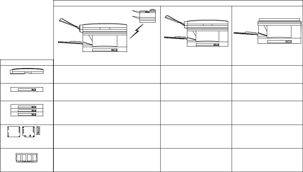
Main unit configuration
GP160F |
GP160DF |
GP160 |
System configuration
|
|
Digital black and white copier (with ADF) |
Digital black and white copier |
|
|
(Copy board cover model) |
|
|
Digital black and white copier and facsimile |
|
|
Installation options |
|
|
|
|
|
|
|
ADF-H1 |
Standard equipment |
Standard equipment |
Option |
|
|
|
|
Cassette Unit D1 |
Option |
Option |
Option |
|
|
|
|
|
Option |
Option |
Option |
Cassette unit E1 |
|
|
|
Modular |
Standard equipment |
Option |
Option |
Modem board NCU board board |
|
|
|
Super G3 FAX board |
|
|
|
|
Option |
Option |
Option |
8MB expanded memory |
|
|
|
iii
iv
COPYRIGHT © 1999 CANON INC. |
CANON GP160 REV.0 FEB. 1999 PRINTED IN JAPAN (IMPRIME AU JAPON) |

CONTENTS
CHAPTER 1 INTRODUCTION
I. |
FEATURES .............................................. |
1-1 |
|
II. |
SPECIFICATIONS ................................... |
1-2 |
|
III. |
NAMES OF PARTS ................................. |
1-6 |
|
|
A. |
External view...................................... |
1-6 |
|
B. |
Cross sectional diagram .................... |
1-8 |
IV. |
OPERATION EXPLANATION................ |
1-10 |
|
|
A. |
Control panel.................................... |
1-10 |
|
B. |
Basic operation ................................ |
1-13 |
|
C. |
Advanced features ........................... |
1-13 |
D. User mode ....................................... |
1-14 |
V.ROUTINE MAINTENANCE TO BE
CARRIED OUT BY THE USER ............. |
1-32 |
|||
VI. SAFETY ................................................. |
1-33 |
|||
A. |
|
|
Laser beam safety |
1-33 |
|
|
|||
B. |
Toner safety ..................................... |
1-36 |
||
VII. COPYING PROCESS ............................ |
1-37 |
|||
A. |
Outline.............................................. |
1-37 |
||
CHAPTER 2 BASIC OPERATION
I. |
BASIC OPERATION ................................ |
2-1 |
|
|
A. |
Function configuration........................ |
2-1 |
|
B. |
Copy operation overview ................... |
2-2 |
II. |
ELECTRICAL CIRCUIT OVERVIEW ....... |
2-3 |
|
III. |
BASIC SEQUENCES............................... |
2-4 |
IV. |
MAIN MOTOR.......................................... |
2-5 |
V.PRINCIPAL CIRCUIT PCB
INPUT/OUTPUT....................................... |
2-6 |
CHAPTER 3 EXPOSURE SYSTEM
I. |
OPERATION OVERVIEW........................ |
3-1 |
B. Charging the magnification ratio ........ |
3-4 |
|
A. Overview ............................................ |
3-1 |
C. Scanning lamp control ....................... |
3-4 |
|
B. Exposure system sequence............... |
3-2 |
III. DISASSEMBLY, ASSEMBLY .................. |
3-5 |
II. |
SCANNER DRIVE SYSTEM.................... |
3-3 |
A. Scanning lamp ................................... |
3-6 |
|
A. Document scanner motor................... |
3-3 |
B. Document scanning motor ................. |
3-8 |
|
|
|
|
|
|
|
|
|
|
CHAPTER 4 IMAGE PROCESSING SYSTEM
I. |
OVERVIEW.............................................. |
4-1 |
II. |
ANALOG IMAGE PROCESSING............. |
4-2 |
|
A. Overview ............................................ |
4-2 |
|
B. CCD/CCD drive circuit ....................... |
4-2 |
|
C. A-D conversion circuit / |
|
|
ABC circuit ......................................... |
4-3 |
III. |
DIGITAL IMAGE PROCESSING.............. |
4-4 |
|
A. Overview ............................................ |
4-4 |
|
B. Shading correction ............................. |
4-5 |
C. |
Magnification ratio process ................ |
4-7 |
D. Edge emphasis / smoothing |
|
|
|
process .............................................. |
4-7 |
E. |
Logarithmic correction........................ |
4-8 |
F. |
Half tone density processing.............. |
4-9 |
G. Binarisation ........................................ |
4-9 |
|
IV. DISASSEMBLY, ASSEMBLY ................ |
4-10 |
|
A. CCD unit .......................................... |
4-11 |
|
COPYRIGHT © 1999 CANON INC. |
CANON GP160 REV.0 FEB. 1999 PRINTED IN JAPAN (IMPRIME AU JAPON) |
v |

CHAPTER 5 LASER EXPOSURE SYSTEM
I. |
OVERVIEW.............................................. |
5-1 |
II. |
BD SIGNAL GENERATION ..................... |
5-3 |
|
A. Overview ............................................ |
5-3 |
|
B. BD generation / detection .................. |
5-3 |
III. |
LASER DRIVER CIRCUIT ....................... |
5-4 |
|
A. Operation ........................................... |
5-4 |
|
B. Laser light intensity control ................ |
5-4 |
IV. |
LASER SCANNER MOTOR |
|
|
CONTROL................................................ |
5-6 |
|
A. Operation outline................................ |
5-6 |
V. |
DISASSEMBLY, ASSEMBLY .................. |
5-7 |
|
A. Laser scanner unit ............................. |
5-8 |
CHAPTER 6 IMAGE FORMATION SYSTEM
I. |
OVERVIEW.............................................. |
6-1 |
IV. |
SEPARATION STATIC CHARGE |
|
||
|
A. Construction....................................... |
6-1 |
|
ELIMINATOR BIAS CONTROL ............... |
6-6 |
||
II. |
PRIMARY CHARGING ROLLER BIAS |
|
|
A. Operation ........................................... |
6-6 |
||
|
CONTROL................................................ |
6-3 |
V. |
DEVELOPING BIAS CONTROL .............. |
6-7 |
||
|
A. |
Outline ............................................... |
6-3 |
|
A. |
Outline ............................................... |
6-7 |
|
B. |
Control operation ............................... |
6-3 |
|
B. |
Operation ........................................... |
6-7 |
III. |
TRANSFER CHARGING ROLLER BIAS |
|
VI. |
RE-CHARGE BIAS CONTROL................ |
6-8 |
||
|
CONTROL................................................ |
6-4 |
|
A. Operation ........................................... |
6-8 |
||
|
A. Overview ............................................ |
6-4 |
VII. |
CARTRIDGE DETECTION ...................... |
6-9 |
||
|
B. |
Bias control ........................................ |
6-5 |
|
A. |
Operation ........................................... |
6-9 |
|
|
|
|
|
|
|
|
|
|
|
|
|
|
|
|
CHAPTER 7 PICK-UP / FEEDING SYSTEM
I. |
OVERVIEW.............................................. |
7-1 |
|
|
A. |
Construction Overveiw ....................... |
7-1 |
II. |
PICK-UP FEEDING OPERATION ........... |
7-2 |
|
|
A. Overveiw ............................................ |
7-2 |
|
III. |
CASSETTE PICK-UP MECHANISM........ |
7-3 |
|
|
A. |
Pick-up oparation ............................... |
7-3 |
|
B. |
Retry pick-up ...................................... |
7-5 |
|
C. Paper size detection .......................... |
7-6 |
|
IV. |
MULTI-FEEDER PICK-UP ....................... |
7-7 |
|
|
A. Overview ............................................ |
7-7 |
|
|
B. |
Multi-feeder pick-up mechanism ........ |
7-8 |
|
C. |
Multi-feeder retry pick-up ................... |
7-9 |
|
D. |
Multi-feeder paper size setting ......... |
7-10 |
V. |
PAPER FEEDING OPERATION............ |
7-12 |
|
|
A. Paper leading edge detection .......... |
7-12 |
|
|
B. |
Paper width detection ...................... |
7-12 |
VI. |
JAM DETECTION .................................. |
7-13 |
|
|
A. Overview .......................................... |
7-13 |
|
|
B. Types of Jam ................................... |
7-14 |
|
|
C. Jam sequence.................................. |
7-14 |
|
VII. DISASSEMBLY, ASSEMBLY ................ |
7-23 |
||
|
A. |
Cassette feeding assembly.............. |
7-24 |
|
B. |
Multi-feeder assembly ...................... |
7-30 |
|
C. |
Registration roller assembly............. |
7-33 |
|
D. |
Feeder assembly ............................. |
7-35 |
CHAPTER 8 FIXING SYSTEM
I. |
OPERATIONAL OVERVIEW ................... |
8-1 |
|
|
A. Overview ............................................ |
8-1 |
|
|
B. |
Fixing pressure roller cleaning ........... |
8-1 |
II. |
FIXING CONTROL................................... |
8-3 |
|
|
A. |
Fixing temperature control ................. |
8-3 |
B. |
Fixing heater safety mechanism ........ |
8-5 |
C. Fixing assembly malfunction |
|
|
|
detector .............................................. |
8-5 |
III. DISASSEMBLY, ASSEMBLY .................. |
8-6 |
|
A. |
Removing the fixing assembly ........... |
8-7 |
vi
COPYRIGHT © 1999 CANON INC. |
CANON GP160 REV.0 FEB. 1999 PRINTED IN JAPAN (IMPRIME AU JAPON) |

CHAPTER 9 EXTERNAL / AUXILIARY MECHANISM
I. |
CONTROL PANEL................................... |
9-1 |
A. Back-up function ................................ |
9-8 |
|
|
A. Overview ............................................ |
9-1 |
B. Back-up Data ................................... |
9-12 |
|
II. |
POWER SUPPLY .................................... |
9-2 |
V. DISASSEMBLY, ASSEMBLY ................ |
9-16 |
|
|
A. Low-voltage power supply circuit ....... |
9-2 |
A. |
Control panel.................................... |
9-17 |
|
B. High voltage power supply circuit ...... |
9-4 |
B. |
Main Motor ....................................... |
9-19 |
|
C. Energy save function control.............. |
9-5 |
C. DC controller PCB............................ |
9-25 |
|
III. |
FAN .......................................................... |
9-7 |
D. Image processor PCB...................... |
9-26 |
|
|
A. Rotation control mechanism .............. |
9-7 |
E. DC power supply PCB ..................... |
9-27 |
|
IV. |
BACK-UP BATTERY................................ |
9-8 |
|
|
|
|
|
|
|
|
|
|
|
|
|
|
|
|
|
|
|
|
|
CHAPTER 10 CASSETTE FEEDER
I. |
OVERVIEW............................................ |
10-1 |
A. Operation ......................................... |
10-7 |
|
II. |
OVERVIEW OF THE ELECTRICAL |
VI. |
JAM DETECTION .................................. |
10-8 |
|
|
CIRCUITS .............................................. |
10-3 |
A. Overview .......................................... |
10-8 |
|
|
A. Overview .......................................... |
10-3 |
B. Jam Sensing .................................... |
10-9 |
|
III. |
FEEDER CONTROLLER PCB |
VII. |
DISASSEMBLY, ASSEMBLY .............. |
10-11 |
|
|
INPUT AND OUTPUT ............................. |
10-4 |
A. Removing the feeder motor ........... |
10-12 |
|
IV. |
OPERATION OVERVIEW...................... |
10-5 |
B. Removing the pick-up/feeder/ |
|
|
|
A. |
Overview .......................................... |
10-5 |
separation motor ............................ |
10-12 |
|
B. |
Basic Sequence .............................. |
10-6 |
C. Removing the pick-up unit ............. |
10-14 |
V. |
FEEDER MOTOR CONTROL................ |
10-7 |
|
|
|
|
|
|
|
|
|
|
|
|
|
|
|
|
|
|
|
|
|
CHAPTER 11 INSTALLATION
I. |
CHOOSING AN SUITABLE INSTALLATION |
C. Loading paper into the cassette....... |
11-8 |
||
|
LOCATION............................................. |
11-1 |
D. Loading paper into the |
|
|
II. |
UNPACKING AND INSTALLATION....... |
11-3 |
|
multi-feeder .................................... |
11-11 |
|
A. Opening the package and removing |
|
E. |
Attaching the tray/Power cord........ |
11-12 |
|
the packing materials ....................... |
11-4 |
F. |
Checking the Copy image.............. |
11-13 |
|
B. Installing the cartridge...................... |
11-5 |
G. |
Setting the Fax machine function .... |
11-13 |
|
|
|
|
|
|
|
|
|
|
|
|
CHAPTER 12 MAINTENANCE AND INSPECTION
I. |
PERIODIC REPLACEMENT PARTS |
.....12-1 |
A. Storage when the packing seal is |
|
II. |
ESTIMATED LIFESPAN OF CONSUMABLE |
intact ................................................ |
12-3 |
|
|
PARTS ................................................... |
12-1 |
B. Storage and handling when the |
|
III. |
BASIC SERVICING PROCEDURES ..... |
12-2 |
packing seal has been opened ........ |
12-4 |
IV. |
CARTRIDGE STORAGE AND |
|
|
|
|
HANDLING............................................. |
12-3 |
|
|
COPYRIGHT © 1999 CANON INC. |
CANON GP160 REV.0 FEB. 1999 PRINTED IN JAPAN (IMPRIME AU JAPON) |
vii |

CHAPTER 13 TROUBLESHOOTING
I. STANDARDS AND ADJUSTMENTS..... |
13-2 |
A. Machanical system .......................... |
13-2 |
B. Electrical System ............................. |
13-9 |
II.IMAGE AND MACHINE MALFUNCTION
|
COUNTERMEASURES ....................... |
13-15 |
|
A. Initial check .................................... |
13-15 |
|
B. Treatment procedures by faulty |
|
|
image type ..................................... |
13-17 |
|
C. Operation malfunction |
|
|
countermeasures ........................... |
13-26 |
III. |
FAULTY FEEDING |
|
|
COUNTERMEASURES ....................... |
13-34 |
|
A. Overview ........................................ |
13-34 |
|
B. Copy paper jam.............................. |
13-35 |
|
C. Faulty feeding ................................ |
13-38 |
IV. |
ELECTRICAL PARTS POSITIONS/ |
|
|
FUNCTIONS ........................................ |
13-39 |
|
A. Clutches, solenoids........................ |
13-40 |
|
B. |
Motor, fan....................................... |
13-42 |
|
C. |
Sensors.......................................... |
13-44 |
|
D. |
Switches, lamps, miscellaneous .... |
13-46 |
|
E. |
PCBs.............................................. |
13-48 |
|
F. |
Variable resistor(VR)/LED/check |
|
|
|
pin listed by PCB plate................... |
13-50 |
V. |
SERVICE MODE.................................. |
13-55 |
|
|
A. Overview ........................................ |
13-55 |
|
|
B. |
Operating Procedures.................... |
13-56 |
|
C. |
Service mode menu list.................. |
13-57 |
|
D. |
SSSW Default Setting.................... |
13-63 |
|
E. |
Parameter settings......................... |
13-78 |
|
F. Test Mode (TEST MODE)............ |
13-111 |
|
VI. |
REPORTS.......................................... |
13-142 |
|
|
A. |
User reports ................................. |
13-142 |
|
B. |
Service report............................... |
13-145 |
VII. USER ERRORS................................. |
13-163 |
||
VIII. SERVICE ERRORS ........................... |
13-170 |
||
APPENDIX
A. |
GENERAL TIMING CHART..................... |
A-1 |
B. |
SIGNALS AND ABBREVIATIONS........... |
A-3 |
C. |
GENERAL CIRCUIT DIAGRAM .............. |
A-5 |
D. LIST OF SPECIAL TOOLS.................... |
A-11 |
E. SOLVENTS AND OILS.......................... |
A-12 |
viii |
COPYRIGHT © 1999 CANON INC. |
CANON GP160 REV.0 FEB. 1999 PRINTED IN JAPAN (IMPRIME AU JAPON) |
CHAPTER 1
INTRODUCTION
This chapter provides an overview of the unit’s specifications, operating method and copying process.
I. |
FEATURES .............................................. |
1-1 |
|
II. |
SPECIFICATIONS ................................... |
1-2 |
|
III. |
NAMES OF PARTS ................................. |
1-6 |
|
|
A. |
External view...................................... |
1-6 |
|
B. |
Cross sectional diagram .................... |
1-8 |
IV. |
OPERATION EXPLANATION................ |
1-10 |
|
|
A. |
Control panel.................................... |
1-10 |
|
B. |
Basic operation ................................ |
1-13 |
|
C. |
Advanced features ........................... |
1-13 |
D. User mode ....................................... |
1-14 |
V.ROUTINE MAINTENANCE TO BE
CARRIED OUT BY THE USER ............. |
1-32 |
|
VI. SAFETY ................................................. |
1-33 |
|
A. |
Laser beam safety....................... |
1-33 |
B. |
Toner safety ..................................... |
1-36 |
VII. COPYING PROCESS ............................ |
1-37 |
|
A. |
Outline.............................................. |
1-37 |
COPYRIGHT © 1999 CANON INC. |
CANON GP160 REV.0 FEB. 1999 PRINTED IN JAPAN (IMPRIME AU JAPON) |

CHAPTER 1 INTRODUCTION
I. FEATURES
<Copy function >
•1200 equivalent × 600dpi high resolution copy
•Due to a new engine, high image quality printing with minute particle super fine toner (diameter 5 microns) has been made possible.
•Due to the integrated drum, toner cassette, the print inner assembly is refreshed when the cartridge is replace.
•256 gradation readings, and realistic half tone rendering.
•Max. 5 way / max. 1100 sheets large volume multi-level pick-up.
•Dual operation - allows copying during fax transmission.
<Fax function >
•High speed Super G3 Fax 2 second transmission (33.6kbps) provided as standard for ordinary telephone lines.
•Able to send and receive A3 size direct copy.
•400dpi scanning resolution ultra high image quality (ultra fine mode).
•600dpi recording resolution ultra high image quality, standard mode 600dpi printing.
•Standard 1megabyte memory (roughly 64 sheets), possibility to expand to maximum 9 megabytes (roughly 576 sheets).
COPYRIGHT © 1999 CANON INC. |
CANON GP160 REV.0 FEB. 1999 PRINTED IN JAPAN (IMPRIME AU JAPON) |
1-1 |

CHAPTER 1 INTRODUCTION
II. SPECIFICATIONS
1. Type |
|
|
|
Item |
Specifications |
|
|
Main unit |
Desk top |
|
|
Copyboard |
Fixed |
|
|
Light source |
Xenon lamp |
|
|
Lens |
Fixed focal lens |
|
|
Photosensitive medium |
OPC (φ 30) |
2. Method
|
Item |
Specifications |
|
|
|
|
|
Copying |
|
|
Indirect electrostatic copying method |
|
|
|
|
Charging |
|
|
AC roller charging method |
|
|
|
|
Exposure |
|
|
Semiconductor laser |
|
|
|
|
Copy density adjustment |
Automatic or manual |
||
|
|
|
|
Developing |
Dry single component jumping method (single unit drum cartridge) |
||
|
|
|
|
Pick-up |
|
Automatic |
Cassette |
|
|
|
|
|
|
Manual |
Multi-feeder |
|
|
|
|
Transfer |
|
|
Roller charging method |
|
|
|
|
Separation |
|
|
Electrostatic separation (static charge elimination) + curvature |
|
|
|
separation |
|
|
|
|
Cleaning |
|
|
Rubber blade |
|
|
|
|
Fixing |
|
|
SURF Fixing |
|
|
|
|
1-2 |
COPYRIGHT © 1999 CANON INC. |
CANON GP160 REV.0 FEB. 1999 PRINTED IN JAPAN (IMPRIME AU JAPON) |

CHAPTER 1 INTRODUCTION
3.Functions
|
Item |
Specifications |
|
|
|
|
|
Types of document |
Sheet, book, three dimensional objects (up to max. 2kg) |
||
|
|
|
|
Max. document size |
A3 / 11 × 17 |
||
|
|
|
|
Wait time |
|
|
15 seconds or less from power ON (20°C) |
|
|
|
|
|
|
|
7 seconds or less from the energy saver mode being cancelled |
|
|
|
|
First copy time |
12 seconds or less (main unit cassette pick-up, 1-to-1 copy, A4, |
||
|
|
|
no AE) |
|
|
|
|
Continuous copying |
1 to 99 sheets |
||
|
|
|
|
Pick-up capacity |
Each cassette 250 sheets *1, multi-feeder 100 sheets (80g/m2) |
||
Delivery tray capacity |
100 sheets *2 |
||
|
|
|
|
Copy size |
|
Cassette |
Max. : A3 / 11 × 17 |
|
|
pick-up |
Min. : A5 |
|
|
|
|
|
|
Multi-feeder |
Max. : A3 |
|
|
pick-up |
Min. : A5 |
|
|
|
|
Types of |
|
Cassette |
Plain paper 64 to 90g/m2, recycled paper 64 to 90g/m2, tracing |
copy paper |
|
pick-up |
paper (GNT-80) *1 |
|
|
|
|
|
|
Multi-feeder |
Plain paper 64 to 128g/m2, tracing paper (SM-1) labels, recycled |
|
|
pick-up |
paper 64 to 128g/m2, OHP *2, tracing paper (GNT-80)*3 |
|
|
|
|
Cassette specifications |
With tab, universal |
||
|
|
|
|
Non image |
|
Leading |
4.0 ± 2.0mm |
width |
|
edge |
|
|
|
|
|
|
|
Trailing |
2.5 ± 2.0mm |
|
|
edge |
|
|
|
|
|
|
|
Front |
2.5 ± 2.0mm |
|
|
|
|
|
|
Rear |
2.5 ± 2.0mm |
|
|
|
|
Auto clear |
|
|
Yes (Standard 2 min., possible to change in units of 1 min. |
|
|
|
between 0 to 9 min) |
|
|
|
|
Energy saver |
Yes (Standard 3 min., possible to change in units of 1 min. |
||
|
|
|
between 3 to 30 min) |
|
|
|
|
Option *4 |
|
|
Cassette feeder (1 step type / 3 step type), 8MB expanded |
|
|
|
memory, ADF, FAX board |
|
|
|
|
*1: 50 or less sheets of tracing paper (GNT-80) by cassette.
*2: 50 or less sheets of OHP sheets by cassette (designated paper). *3: 1 or less sheets of tracing paper (GNT-80) by multi-feeder.
*4: Differs depending on the main unit configuration.
COPYRIGHT © 1999 CANON INC. |
CANON GP160 REV.0 FEB. 1999 PRINTED IN JAPAN (IMPRIME AU JAPON) |
1-3 |

CHAPTER 1 INTRODUCTION
4. Other
|
Item |
|
Specifications |
|
|
|
|
|
|
Operating |
Temperature range |
|
5 to 35°C |
|
|
|
|
|
|
environment |
Humidity range |
|
10 to 90% RH |
|
|
|
|
|
|
|
Atmospheric pressure |
709 to 1013hpa |
|
|
|
range |
|
|
|
|
|
|
|
|
Power |
Main unit |
|
|
|
supply |
GP160 |
|
GP160DF |
|
|
• 230V(ITA): |
PNSxxxxx |
• 230V(ITA): |
PHLxxxxx |
|
• 230V(UK): |
QCTxxxxx |
• 230V(UK): |
QCLxxxxx |
|
• 230V(FRN): |
SBTxxxxx |
• 230V(FRN): SBRxxxxx |
|
|
• 230V(GER): |
TBTxxxxx |
• 230V(GER): TBQxxxxx |
|
|
• 230V(AMS): |
UEHxxxxx |
• 230V(AMS): UEFxxxxx |
|
|
• 230V(CA): |
RCXxxxxx |
|
|
|
• 230V(Others):PHXxxxxx |
|
|
|
|
GP160F |
|
|
|
|
• 230V(ITA): |
PHTxxxxx |
|
|
|
• 230V(UK): |
QCMxxxxx |
|
|
|
• 230V(FRN): |
SBSxxxxx |
|
|
|
• 230V(GER): |
TBRxxxxx |
|
|
|
• 230V(AMS): |
UEGxxxxx |
|
|
|
• 230V(CA): |
RCWxxxxx |
|
|
|
• 230V(Others):PHMxxxxx |
|
|
|
|
|
|
||
|
Cassette Feeding Module-D1 |
Supplied by main unit : ZCRxxxxx |
||
|
|
|
||
|
Cassette Feeding Module-E1 |
Supplied by main unit : ZHRxxxxx |
||
|
|
|
|
|
Power |
Maximum |
|
Approx. 800W |
|
|
|
|
|
|
consumption |
Standby |
|
Approx. 20W |
|
|
|
|
|
|
|
Energy saving mode |
Approx. 14W |
|
|
|
|
|
|
|
Operating |
When in operation |
|
66dB or less |
|
|
|
|
|
|
noise |
Standby |
|
40dB or less |
|
|
|
|
|
|
Dimensions |
Width |
|
616 (mm) / 24.25” |
|
|
|
|
|
|
|
Depth |
|
640 (mm) / 25.20” |
|
|
|
|
|
|
|
Height |
|
427 (mm) / 16.81” (Including ADF) |
|
|
|
|
|
|
Mass |
|
|
48.8kg 107.59 Ò |
|
|
|
|
|
|
Storage of |
Copy paper |
|
Store with the package closed and avoid |
|
consumable |
|
|
humidity |
|
|
|
|
|
|
items |
Cartridge |
|
Refer to page 12-3 |
|
|
|
|
|
|
1-4 |
COPYRIGHT © 1999 CANON INC. |
CANON GP160 REV.0 FEB. 1999 PRINTED IN JAPAN (IMPRIME AU JAPON) |

CHAPTER 1 INTRODUCTION
5. Copy speed
Reproduction mode |
Size |
Copy paper size |
No. of copies / minute |
|
Direct copy |
|
A4 (210 × 297mm) |
A4 |
16 |
|
|
A3 (297 × 420mm) |
A3 |
9 |
|
|
B4 (257 × 364mm) |
B4 |
10 |
|
|
A4R (297 × 210mm) |
A4R |
9 |
|
|
B5 (182 × 257mm) |
B5 |
16 |
|
|
B5R (257 × 182mm) |
B5R |
12 |
|
|
A4 (148.5 × 210mm) |
A5 |
12 |
|
|
LTR (216 × 279mm) |
LTR |
16 |
|
|
LTRR (279 × 216mm) |
LTRR |
9 |
|
|
LGL (216 × 356mm) |
LGL |
9 |
|
|
11 × 17 (279 × 432mm) |
11 × 17 |
9 |
|
|
|
|
|
Specifications are subject to change for the sake of product improvements.
COPYRIGHT © 1999 CANON INC. |
CANON GP160 REV.0 FEB. 1999 PRINTED IN JAPAN (IMPRIME AU JAPON) |
1-5 |

CHAPTER 1 INTRODUCTION
III. NAMES OF PARTS
A.External view
Main unit
ADF standard equipment model
[2]
[3]
[1] |
|
|
[4] |
|
|
[5] |
|
|
[7] |
|
[10] |
|
[8] |
[6] |
|
[9] |
|
Figure 1-301 |
Figure 1-302 |
|
Copyboard cover model |
|
|
[2] |
|
|
[1] |
|
|
[4] |
|
|
[5] |
|
|
[7] |
|
[10] |
|
|
|
|
[8] |
[6] |
|
[9] |
|
Figure 1-303 |
Figure 1-304 |
|
Cassette feeder (accessory) |
|
|
[4]
[3]
[1] |
[2] |
|
Figure 1-305
1-6 |
COPYRIGHT © 1999 CANON INC. |
CANON GP160 REV.0 FEB. 1999 PRINTED IN JAPAN (IMPRIME AU JAPON) |

|
|
|
|
CHAPTER 1 INTRODUCTION |
|
|
|
|
|
Main unit |
|
|
|
|
|
|
|
||
[1] |
Control panel |
[6] |
Right lower cover |
|
[2] |
ADF |
[7] |
Front cover |
|
[3] |
Document delivery tray |
[8] |
Printer unit release handle |
|
[4] |
Delivery tray |
[9] |
Printer unit |
|
[5] |
Cassette |
[10] |
Multi feeder tray |
|
Cassette feeder (accessory)
[1]Cassette feeder
[2]Cassette
[3]Right door
[4]Feeder lifting handle
COPYRIGHT © 1999 CANON INC. |
CANON GP160 REV.0 FEB. 1999 PRINTED IN JAPAN (IMPRIME AU JAPON) |
1-7 |

CHAPTER 1 INTRODUCTION
B.Cross sectional diagram
[1] |
[3] [5] |
[7] |
[9] |
[11] |
[13] |
[15] [17] |
[19] |
[21] |
|
||||||||||||||||||||||||||
|
[2] |
[4] |
|
|
[6] |
|
[8] |
[10] |
|
[12] |
|
[14] [16] |
|
[18] [20] |
|
[22] |
|||||||||||||||||||
|
|
|
|
|
|
|
|
|
|
|
|
|
|
|
|
|
|
|
|
|
|
|
|
|
|
|
|
|
|
|
|
|
|
|
|
|
|
|
|
|
|
|
|
|
|
|
|
|
|
|
|
|
|
|
|
|
|
|
|
|
|
|
|
|
|
|
|
|
|
|
|
|
|
|
|
|
|
|
|
|
|
|
|
|
|
|
|
|
|
|
|
|
|
|
|
|
|
|
|
|
|
|
|
|
|
|
|
|
|
|
|
|
|
|
|
|
|
|
|
|
|
|
|
|
|
|
|
|
|
|
|
|
|
|
|
|
|
|
|
|
|
|
|
|
|
|
|
|
|
|
|
|
|
|
|
|
|
|
|
|
|
|
|
|
|
|
|
|
|
|
|
|
|
|
|
|
|
|
|
|
|
|
|
|
|
|
|
|
|
|
|
|
|
|
|
|
|
|
|
|
|
|
|
|
|
|
|
|
|
|
|
|
|
|
|
|
|
|
|
|
|
|
|
|
|
|
|
|
|
|
|
|
|
|
|
|
|
|
|
|
|
|
|
|
|
|
|
|
|
|
|
|
|
|
|
|
|
|
|
|
|
|
|
|
|
|
|
|
|
|
|
|
|
|
|
|
|
|
|
|
|
|
|
|
|
|
|
|
|
|
|
|
|
|
|
|
|
|
|
|
|
|
|
|
|
|
|
|
|
|
|
|
|
|
|
|
|
|
|
|
|
|
|
|
|
|
|
|
|
|
|
|
|
|
|
|
|
|
|
|
|
|
|
|
|
|
|
|
|
|
|
|
|
|
|
|
|
|
|
|
|
|
|
|
|
|
|
|
|
|
|
|
|
|
|
|
|
|
|
|
|
|
|
|
|
|
|
|
|
|
|
|
|
|
|
|
|
|
|
|
|
|
|
|
|
|
|
|
|
|
|
|
|
|
|
|
|
|
|
|
|
|
|
|
|
|
|
|
|
|
|
|
[37] |
[35] |
[33] |
[31] |
[29] |
[27] |
[25] |
[23] |
|||
[38] |
[36] |
[34] |
[32] |
[30] |
[28] |
[26] |
[24] |
||||
Figure 1-306
1-8 |
COPYRIGHT © 1999 CANON INC. |
CANON GP160 REV.0 FEB. 1999 PRINTED IN JAPAN (IMPRIME AU JAPON) |
|
|
|
CHAPTER 1 INTRODUCTION |
|
|
|
|
|
|
|
|
|
|
|
[1] |
Mirror 3 |
[23] Vertical path roller (Main unit pick-up |
||
[2] |
Mirror 2 |
assembly) |
||
[3] |
White reference assembly |
[24] Vertical path roller (Cassette feeder) |
||
[4] |
Mirror 1 |
[25] Separation roller (Main unit pick-up |
||
[5] |
Document scanning lamp |
assembly) |
||
[6] |
Copyboard glass |
[26] Separation roller (Cassette feeder) |
||
[7] |
Fixing delivery roller |
[27] Feed roller (Cassette feeder) |
||
[8] |
Cleaning roller |
[28] Feed roller (Main unit pick-up |
||
[9] |
Fixing film |
assembly) |
||
[10] CCD |
[29] Pick-up roller (Cassette feeder) |
|||
[11] Lens |
[30] Pick-up roller (Main unit pick-up |
|||
[12] Charge eliminator |
assembly) |
|||
[13] Laser scanner unit |
[31] Transfer charging roller |
|||
[14] Photosensitive drum |
[32] Separation static charge elimination |
|||
[15] Primary charging roller |
[33] Paper sensor lever (Cassette feeder) |
|||
[16] Mirror 4 |
[34] Paper sensor lever (Main unit pick- |
|||
[17] Developing cylinder |
up assembly) |
|||
[18] Cartridge |
[35] Feed assembly |
|||
[19] Registration pressure roller |
[36] Fixed pressure roller |
|||
[20] Registration roller |
[37] Paper cassette (Main unit) |
|||
[21] Multi-feeder pick-up roller |
[38] Paper cassette (Cassette feeder) |
|||
[22] Multi-feeder tray |
|
|
|
|
COPYRIGHT © 1999 CANON INC. |
CANON GP160 REV.0 FEB. 1999 PRINTED IN JAPAN (IMPRIME AU JAPON) |
1-9 |

CHAPTER 1 INTRODUCTION
IV. OPERATION EXPLANATION
A.Control panel
[12][15]
[4] |
[5] |
[6][10][11] [13] [14] |
[16] |
[17] |
In Use/Memory |
Error |
Coded |
Direct |
|
|
|
Fax Monitor Program Dial Hook R Redial |
Stamp |
TX |
|
|
Reset |
|
|
DEF |
Clear |
|
|
|
|
|
|
|
Energy Saver |
|
|
|
ABC |
|
|
|
|
|
|
|
|
|||
[1] |
|
|
|
|
|
|
1 |
2 |
3 |
4 |
5 |
6 |
7 |
[24] |
|
Data Registration |
GHI |
JKL |
MNO |
|
|
|
|
|
|
|
|
||
[2] |
|
|
|
|
|
Stop |
8 |
9 |
10 |
11 |
12 |
13 |
14 |
|
|
|
PRS |
TUV |
WXY |
Start |
|
|
|
|
|
|
|
|
|
[3] |
Copy Special Features |
|
|
|
|
|
15 |
16 |
17 |
18 |
19 |
20 |
21 |
|
|
|
Tone |
OPER |
SYMBOLS |
|
22 |
23 |
24 |
25 |
26 |
27 |
28 |
|
|
|
Return |
Set |
|
|
|
|
|
|
|
|
|
|
|
|
|
|
|
|
|
|
|
|
|
|
|
|
|
57 ~ 84 |
29 ~ 56 |
[18]
[7] [8] [9] |
[19] [20] [21] [23] |
[25] |
[22]
Figure 1-401
1-10 |
COPYRIGHT © 1999 CANON INC. |
CANON GP160 REV.0 FEB. 1999 PRINTED IN JAPAN (IMPRIME AU JAPON) |
|
|
|
CHAPTER 1 INTRODUCTION |
|
|
|
|
|
|
|
|
|
|
|
No. |
Key name |
Function outline |
|
|
|
|
|
|
|
[1] |
Display contrast VR |
Adjusts the control panel contrast. |
|
|
[2] |
Collate key |
Performs sort copying when copying with the ADF. |
|
|
[3]Copy special features Performs frame erasing, margin, transferring and 2 in 1
|
|
copying. |
[4] |
COPY |
Changes over to the copy mode. |
[5] |
FAX* |
Changes over to the fax mode. |
[6] |
PRINT/SCAN* |
Changes over to the printer mode. |
[7] |
Display selection |
Selects functions shown in the display. |
[8] |
Return |
Returns to the previous display. |
[9] |
Set |
Confirms the registration/setting. |
[10] |
Fax Monitor* |
Confirms the transmission conditions, clears transmission |
|
|
reservations. |
[11] |
Program* |
Registers a single operation that can be selected by simply |
|
|
pushing this key. |
[12] |
Coded Dial* |
Uses speed dial. |
[13] |
Hook* |
Ability to listen to the other party’s response through the |
|
|
speaker. |
[14] |
R* |
Press to dial an outside telephone number, or an extension |
|
|
number, when the fax is connected through a swichboard |
|
|
(PBX). |
[15] |
Redial* |
Redials the last number dialed. |
[16] |
Stamp* |
Stamps a completed transmission. |
[17] |
Direct TX* |
Executes direct transmission. |
[18] |
Reset |
Resets the copy mode. |
[19] |
Data registration |
Calls up the user mode setting display. |
[20] |
Numeric key |
Dials the telephone number, sets the number of copies, etc.. |
[21] |
Clear |
Clears the registration/setting. |
[22] |
Start |
Starts transmission / copying. |
[23] |
Stop |
Stops transmission / copying. |
[24] |
Energy saver |
Clears the energy saver mode. |
[25] |
One touch panel* |
One touch dial key. |
*: Not available on copiers not equipped with the fax function
**: Not available on copiers not equipped with the printer function
COPYRIGHT © 1999 CANON INC. |
CANON GP160 REV.0 FEB. 1999 PRINTED IN JAPAN (IMPRIME AU JAPON) |
1-11 |

CHAPTER 1 INTRODUCTION
Slide seitch (Normally off for user speration) |
Spealer volume switch |
|||||||
|
|
|
|
|
|
|
|
|
|
|
|
|
|
|
|
|
|
|
|
Confidential |
Relay |
Pause |
|
Delayed Transmission Polling |
Mailbox |
Broadcast |
Delate |
||
|
Memory |
|
|
|
|
Memory Box |
Reception |
Transfer |
|
|
Space |
Memory |
Report |
|
|
Clear |
Set |
Reference |
|
|
|||
|
|
|
Receive |
Tone/+ |
D . T . |
TTI Selector |
Subaddress |
Password |
Mode |
||
|
|
Figure 1-402 |
|
Key name |
|
Function outline |
|
|
|
||
Delayed Transmission* |
Designates the sending time of the transmission. |
||
Polling* |
|
Designates polling transmission. |
|
Confidential Mailbox* |
Designates confidential transmission. |
||
Relay Broadcast* |
|
Designates relay origination transmission. |
|
Delete* |
|
Deletes the input characters. |
|
Pause |
|
Inserts a pause in the telephone number. |
|
Memory Box* |
|
Prints documents when they have been stored in the Memory box, |
|
|
|
or when a document has been reception by the memory box. |
|
Memory Reception* |
|
Receives in memory and designates the printing of reception |
|
|
|
documents. |
|
Transfer* |
|
Designates the transfer of reception documents to other faxes. |
|
Memory Reference* |
|
Designates the confirmation or deletion of memory contents. |
|
Report* |
|
Designates the output of each kind of report and list. |
|
Clear |
|
Designates the deletion of registration/setting. |
|
Set |
|
Designates the confirmation of registered/set contents. |
|
TTI Selector* |
|
Used when changing the senders name. |
|
Subaddress* |
|
Used when performing a subaddress transmission. |
|
Password* |
|
Used when transmitting with a fax standard password. |
|
Receive mode* |
|
Designates switching to receive mode. |
|
Tone/+ |
|
Connects to information services that accept tone dialing only, |
|
|
|
even if you are using a rotary pulse line or enters a plus sign |
|
|
|
in a fax number. And enters a plus sign when registering your |
|
|
|
fax number. |
|
DT |
|
Press to confirm the dial tone when registering a telephone |
|
|
|
number. |
|
Space* |
|
Creates a space between rows of numbers or characters. |
|
Shift key |
|
Use to selecting items on the control panel. |
|
*: Not available on copiers not equipped with the fax function |
|||
1-12 |
COPYRIGHT © 1999 CANON INC. |
CANON GP160 REV.0 FEB. 1999 PRINTED IN JAPAN (IMPRIME AU JAPON) |
|

CHAPTER 1 INTRODUCTION
B.Basic operation
The basic operations of the copy keys on the operation panel are listed below.
Key name |
Details |
|
|
Reproduction ratio key |
Selects fixed ratio change (2R2E) or zoom (50 to 200%). |
|
|
Paper selection key |
Selects the pick-up cassette. |
|
|
Scanning mode key |
Selects the scanning density (automatic, F1 to F9) and the |
|
image quality (character, character/photo, photo). |
|
|
|
Table 1-401 |
C.Advanced features
The basic operations of the advanced copy feature keys on the operation panel are listed below.
Key name |
Details |
|
|
|
|
Page separation |
Performs left/right page separation copy in the book mode. |
|
|
|
Sets the left and right margins and designates the 2-page |
|
|
spread copy size. |
|
|
|
Binding margin |
Creates a binding margin on the paper. Sets the margin |
|
|
|
position (left margin, right margin, top margin, bottom mar- |
|
|
gin) and also the margin width (1 to 10mm). |
|
|
|
Frame erasing |
Sets the frame erasing position. |
|
|
|
|
|
Document frame |
Copies with document frame erasing. |
|
erasing |
|
|
|
|
|
Sheet frame |
Creates a margin around the outside of the document and |
|
erasing |
copies. |
|
|
|
|
Book frame |
When copying books, etc., the surrounding and center |
|
erasing |
margins are deleted. |
|
|
|
|
Punch hole |
Erases punch holes from the left margin of copied docu- |
|
erasing |
ments. |
|
|
|
2 in 1 copy |
Inputs the document size and paper size and designates 2 |
|
|
|
in 1 copying. |
|
|
|
|
|
Table 1-402 |
COPYRIGHT © 1999 CANON INC. |
CANON GP160 REV.0 FEB. 1999 PRINTED IN JAPAN (IMPRIME AU JAPON) |
1-13 |

CHAPTER 1 INTRODUCTION
D.User mode
When the registration/setting key is pressed on the control panel, the user mode setting screen is displayed.
The construction of the user mode is shown below.
1.User mode for copies equipped with the fax function
REGISTRATION/SETTING
01 DATA REGISTRATION  01 USER SETTINGS
01 DATE/TIME SETTING
02 UNIT TEL NUMBER
03 UNIT NAME
04 SENDER NAME REG. (9)
|
|
05 TX TERMINAL ID |
|
|
|
|
|
01 ON |
|
|
|
|
01 TTI POSITION |
|
|
|
|
|
01 OUTSIDE IMAGE |
||||||||||||||||||||||
|
|
|
|
|
|
|
|
|
|
|
02 OFF |
|
|
|
|
|
|
|
|
|
|
|
|
|
|
|
|
|
02 INSIDE IMAGE |
||||||||||||
|
|
|
|
|
|
|
|
|
|
|
|
|
|
|
|
|
|
|
|
|
|
|
|
|
|
|
|
||||||||||||||
|
|
|
|
|
|
|
|
|
|
|
|
|
|
|
|
|
|
02 TEL NUMBER MARK |
|
|
|
01FAX |
|
||||||||||||||||||
|
|
|
|
|
|
|
|
|
|
|
|
|
|
|
|
|
|
|
|
||||||||||||||||||||||
|
|
06 DENSITY CONTROL |
|
|
01 LIGHT |
3 |
|
|
|
|
|
|
|
|
|
|
|
|
|
|
|
|
|
|
02 TEL |
|
|||||||||||||||
|
|
|
|
|
|
|
|
|
|
|
|
|
|
|
|
|
|
|
|
|
|
|
|||||||||||||||||||
|
|
|
|
|
|
|
|
|
|
|
|
|
|
|
|
|
|
|
|
|
|
|
|
|
|
|
|||||||||||||||
|
|
|
|
|
|
|
|
|
|
|
02 STANDARD 5 |
|
|
|
|
|
|
|
|
|
|
|
|
|
|
|
|
|
|
|
|
|
|
||||||||
|
|
|
|
|
|
|
|
|
|
|
|
|
|
|
|
|
|
|
|
|
|
|
|
|
|
|
|
|
|
|
|
|
|||||||||
|
|
07 PROGRAM KEY REG |
|
|
03 DARK |
7 |
|
|
|
|
|
|
|
|
|
|
|
|
|
|
|
|
|
|
|
|
|
|
|
||||||||||||
|
|
|
|
|
|
|
|
|
|
|
|
|
|
|
|
|
|
|
|
|
|
|
|
|
|
||||||||||||||||
|
|
|
|
01 PRINT REPORT |
|
|
|
|
|
|
|
|
|
|
|
|
|
|
|
|
|
|
|
|
|
|
|||||||||||||||
|
|
|
|
|
|
|
|
|
|
|
|
|
|
|
|
|
|
|
|
|
|
|
|
|
|
||||||||||||||||
|
|
|
|
|
|
|
|
|
|
|
02 REPORT |
|
|
|
|
|
|
|
|
|
|
|
|
|
|
|
|
|
|
|
|
|
|
||||||||
|
|
|
|
|
|
|
|
|
|
|
|
|
|
|
|
|
|
|
|
|
|
|
|
|
|
|
|
|
|
|
|
|
|||||||||
|
|
|
|
|
|
|
|
|
|
|
03 TONE |
|
|
|
|
|
|
|
|
|
|
|
|
|
|
|
|
|
|
|
|
|
|
|
|
|
|
|
|||
|
|
|
|
|
|
|
|
|
|
|
|
|
|
|
|
|
|
|
|
|
|
|
|
|
|
|
|
|
|
|
|
|
|
|
|
|
|
||||
|
|
|
|
|
|
|
|
|
|
|
04 SENDER'S NAME |
|
|
|
|
|
|
|
|
|
|
|
|
|
|
|
|
|
|
|
|
|
|
||||||||
|
|
|
|
|
|
|
|
|
|
|
|
|
|
|
|
|
|
|
|
|
|
|
|
|
|
|
|
|
|
|
|
|
|||||||||
|
|
|
|
|
|
|
|
|
|
|
05 SUBADDRESS |
|
|
|
|
|
|
|
|
|
|
|
|
|
|
|
|
|
|
|
|
|
|
||||||||
|
|
|
|
|
|
|
|
|
|
|
|
|
|
|
|
|
|
|
|
|
|
|
|
|
|
|
|
|
|
|
|
|
|||||||||
|
|
08 OFFHOOK ALARM |
|
|
|
|
|
|
06 RX MODE |
|
|
|
|
|
|
|
|
|
|
|
|
|
|
|
|
|
|
|
|
|
|
||||||||||
|
|
|
|
|
|
|
|
|
|
|
|
|
|
|
|
|
|
|
|
|
|
|
|
|
|
|
|
|
|
||||||||||||
|
|
|
|
|
|
|
01 ON |
|
|
|
|
|
|
|
|
|
|
|
|
|
|
|
|
|
|
|
|
|
|
|
|
|
|
|
|||||||
|
|
|
|
|
|
|
|
|
|
|
|
|
|
|
|
|
|
|
|
|
|
|
|
|
|
|
|
|
|
|
|
|
|
|
|||||||
|
|
09 VOLUME CONTROL |
|
|
|
|
|
02 OFF |
|
|
|
|
|
|
|
01 ON |
|
|
(1 ~ 3) 1 |
|
|
|
|||||||||||||||||||
|
|
|
|
|
|
|
|
|
|
|
|
|
|
|
|
|
|
|
|||||||||||||||||||||||
|
|
|
|
01 KEYPAD VOLUME |
|
|
|
|
|
|
|
||||||||||||||||||||||||||||||
|
|
|
|
|
|
|
|
|
|
|
|
|
|
|
|
|
|
|
|
|
|
02 OFF |
|
|
(1 ~ 3) 1 |
|
|
|
|||||||||||||
|
|
|
|
|
|
|
|
|
|
|
|
|
|
|
|
|
|
|
|
|
|
|
|
|
|
||||||||||||||||
|
|
|
|
|
|
|
|
|
|
02 ALARM VOLUME |
|
|
|
01 ON |
|
|
|
|
|||||||||||||||||||||||
|
|
|
|
|
|
|
|
|
|
|
|
|
|
|
|
|
|
|
|
|
|
02 OFF |
|
|
|
|
|
|
|
|
(1 ~ 3) 1 |
||||||||||
|
|
|
|
|
|
|
|
|
|
|
|
|
|
|
|
|
|
|
|
|
|
|
|
|
|
|
|
|
|
||||||||||||
|
|
|
|
|
|
|
|
|
|
03 TX DONE TONE |
|
|
|
01 ON |
|
|
|
|
|
|
|
|
|||||||||||||||||||
|
|
|
|
|
|
|
|
|
|
|
|
|
|
|
|
|
|
|
|
|
|
02 ERROR ONLY |
|
(1 ~ 3) 1 |
|||||||||||||||||
|
|
|
|
|
|
|
|
|
|
|
|
|
|
|
|
|
|
|
|
|
|
|
|||||||||||||||||||
|
|
|
|
|
|
|
|
|
|
|
|
|
|
|
|
|
|
|
|
|
|
03 OFF |
|
|
|
|
|
|
|
|
(1 ~ 3) 1 |
||||||||||
|
|
|
|
|
|
|
|
|
|
|
|
|
|
|
|
|
|
|
|
|
|
|
|
|
|
|
|
|
|
||||||||||||
|
|
|
|
|
|
|
|
|
|
04 RX DONE TONE |
|
|
|
01 ON |
|
|
|
|
|
|
|
|
|||||||||||||||||||
|
|
|
|
|
|
|
|
|
|
|
|
|
|
|
|
|
|
|
|
|
|
02 ERROR ONLY |
|
(1 ~ 3) 1 |
|||||||||||||||||
|
|
|
|
|
|
|
|
|
|
|
|
|
|
|
|
|
|
|
|
|
|
|
|||||||||||||||||||
|
|
|
|
|
|
|
|
|
|
|
|
|
|
|
|
|
|
|
|
|
|
03 OFF |
|
|
|
|
|
|
|
|
|
|
|
||||||||
|
|
|
|
|
|
|
|
|
|
|
|
|
|
|
|
|
|
|
|
|
|
|
|
|
|
|
|
|
|
|
|
|
|||||||||
|
|
|
|
|
|
|
|
|
|
05 PRINTING DONE TONE |
|
|
|
|
01 ON |
|
|
|
|
(1 ~ 3) 1 |
|||||||||||||||||||||
|
|
|
|
|
|
|
|
|
|
|
|
|
|
|
|
|
|
||||||||||||||||||||||||
|
|
|
|
|
|
|
|
|
|
|
|
|
|
|
|
|
|
|
|
|
|
|
|
|
|
|
|
02 ERROR ONLY |
|
(1 ~ 3) 1 |
|||||||||||
|
|
|
|
|
|
|
|
|
|
|
|
|
|
|
|
|
|
|
|
|
|
|
|
|
|
|
|
|
|||||||||||||
|
|
|
|
|
|
|
|
|
|
06 SCANNING DONE TONE |
|
|
|
|
03 OFF |
|
|
|
|||||||||||||||||||||||
|
|
|
|
|
|
|
|
|
|
|
|
|
|
|
|
||||||||||||||||||||||||||
|
|
|
|
|
|
|
|
|
|
|
|
|
|
01 ON |
|
|
|
|
(1 ~ 3) 1 |
||||||||||||||||||||||
|
|
|
|
|
|
|
|
|
|
|
|
|
|
|
|
|
|
|
|
|
|
|
|
|
|
|
|
02 ERROR ONLY |
|
(1 ~ 3) 1 |
|||||||||||
|
|
|
|
|
|
|
|
|
|
|
|
|
|
|
|
|
|
|
|
|
|
|
|
|
|
|
|
|
|||||||||||||
|
|
|
|
|
|
|
|
|
|
07 COPYING DONE TONE |
|
|
|
|
03 OFF |
|
|
|
|||||||||||||||||||||||
|
|
|
|
|
|
|
|
|
|
|
|
|
|
|
|
||||||||||||||||||||||||||
|
|
|
|
|
|
|
|
|
|
|
|
|
|
01 ON |
|
|
|
|
(1 ~ 3) 1 |
||||||||||||||||||||||
|
|
|
|
|
|
|
|
|
|
|
|
|
|
|
|
|
|
||||||||||||||||||||||||
|
|
10 TEL LINE TYPE |
|
|
|
|
|
|
|
01 ROTARY PULSE |
|
|
|
|
|
|
|
|
02 ERROR ONLY |
|
(1 ~ 3) 1 |
||||||||||||||||||||
|
|
|
|
|
|
|
|
|
|
|
|
|
|
|
|
|
|
||||||||||||||||||||||||
|
|
|
|
|
|
|
|
|
|
|
|
|
03 OFF |
|
|
|
|||||||||||||||||||||||||
|
|
|
|
|
|
|
|
|
|
|
|
|
|
|
|
|
|
||||||||||||||||||||||||
|
|
11 R-KEY SETTING |
|
|
|
|
|
|
|
02 TOUCH TONE |
|
|
|
|
|
|
|
|
|
|
|
|
|
|
|
|
|
|
|
|
|
|
|||||||||
|
|
|
|
|
|
|
|
|
|
|
|
|
|
|
|
|
|
|
|
|
|
|
|
|
|
|
|
|
|
|
|||||||||||
|
|
|
|
01 PSTN |
|
|
|
|
|
|
|
|
|
|
|
|
|
|
|
|
|
|
|
|
|
|
|
|
|
|
|
||||||||||
|
|
|
|
|
|
|
|
|
|
|
|
|
|
|
|
|
|
|
|
|
|
|
|
|
|
|
|
|
|
|
|||||||||||
|
|
|
|
|
|
|
|
|
|
02 PBX |
|
|
|
|
|
01 PREFIX |
|
|
|
|
|
|
|
|
|
|
|
|
|
|
|
|
|
|
|
|
|
|
|||
|
|
|
|
|
|
|
|
|
|
|
|
|
|
|
|
|
|
|
|
|
|
|
|
|
|
|
|
|
|
|
|
|
|
|
|
|
|||||
|
|
|
|
|
|
|
|
|
|
|
|
|
|
|
|
|
|
02 HOOKING |
|
|
|
|
|
|
|
|
|
|
|
|
|
|
|
|
|||||||
|
|
|
|
|
|
|
|
|
|
|
|
|
|
|
|
|
|
|
|
|
|
|
|
|
|
|
|
|
|
|
|
|
|
||||||||
|
|
|
|
|
|
|
|
|
|
|
|
|
|
|
|
|
|
03 EARTH CONNECTION |
|
|
|
||||||||||||||||||||
|
|
|
|
|
|
|
|
|
|
|
|
|
|
|
|
|
|
|
|
|
|||||||||||||||||||||
|
|
|
|
|
|
|
|
|
|
|
Figure 1-403 |
|
|
|
|
|
|
|
|
|
|
|
|
|
|
|
|
|
|
|
|
|
|
||||||||
1-14 |
|
COPYRIGHT © 1999 CANON INC. |
CANON GP160 REV.0 FEB. 1999 PRINTED IN JAPAN (IMPRIME AU JAPON) |
||||||||||||||||||||||||||||||||||||||

CHAPTER 1 INTRODUCTION
|
|
|
|
|
02 REPORT SETTINGS |
|
|
|
|
|
|
|
|
|
|
|
|
|
|
|
|
|
|||||||||||||
|
|
|
|
|
|
|
|
|
|
|
|
|
|
|
|
|
|
|
|
|
|||||||||||||||
|
|
|
|
|
|
|
|
|
|
|
|
|
|
|
|
|
|
|
|
|
|
|
|
|
|
|
|
|
|
|
|
|
|
|
|
|
|
01 TX REPORT |
|
|
|
|
|
|
|
|
|
|
|
|
|
|
|
|
|
|
|
|
|
|
|
|
|
|
|||||||
|
|
|
|
|
|
|
|
|
|
|
|
|
|
|
|
|
|
|
|
|
|
|
|
|
|
|
|||||||||
|
|
|
|
|
|
|
|
|
|
|
|
|
|
|
|
|
|
|
|
|
|
|
|
|
|
|
|
|
|
|
|
|
|
|
|
|
|
|
|
|
01 OUTPUT NO |
|
|
|
|
|
|
|
|
|
|
|
|
|
|
|
|
|
|
|
|
|
|
|
|
||||||
|
|
|
|
|
|
|
|
|
|
|
|
|
|
|
|
|
|
|
|
|
|
|
|
|
|
|
|
|
|||||||
|
|
|
|
|
02 PRINT ERROR ONLY |
|
|
|
|
REPORT WITH TX IMAGE |
|
|
|
01 OFF |
|||||||||||||||||||||
|
|
|
|
|
|
|
|
|
|
|
|
||||||||||||||||||||||||
|
|
|
|
|
|
|
|
|
|
|
|
|
|
|
|
|
|
|
|
|
|
|
|
|
|
|
|
|
|
|
|
|
|
02 ON |
|
|
|
|
|
|
03 OUTPUT YES |
|
|
REPORT WITH TX IMAGE |
|
|
|
|
|
01 OFF |
|||||||||||||||||||||
|
|
|
|
|
|
|
|
|
|
|
|
||||||||||||||||||||||||
|
|
|
|
|
|
|
|
|
|
|
|
||||||||||||||||||||||||
|
|
|
|
|
|
|
|
|
|
|
|
|
|
|
|
|
|
|
|
|
|
|
|
|
|
|
|
|
|
02 ON |
|
|
|||
|
|
02 RX REPORT |
|
|
|
01 OUTPUT NO |
|
|
|
||||||||||||||||||||||||||
|
|
|
|
|
|
|
|
|
|
|
|
|
|||||||||||||||||||||||
|
|
|
|
|
|
|
|
|
|
02 PRINT ERROR ONLY |
|
|
|
|
|
|
|
|
|||||||||||||||||
|
|
|
|
|
|
|
|
|
|
|
|
|
|
|
|
|
|
||||||||||||||||||
|
|
|
|
|
|
|
|
|
|
03 OUTPUT YES |
|
|
|
|
|
|
|
|
|||||||||||||||||
|
|
|
|
|
|
|
|
|
|
|
|
|
|
|
|
|
|
||||||||||||||||||
|
|
03 CONFID. RX REPORT |
|
|
|
|
01 OUTPUT NO |
|
|
|
|
|
|
|
|
||||||||||||||||||||
|
|
|
|
|
|
|
|
|
|
|
|
|
|
||||||||||||||||||||||
|
|
|
|
|
|
|
|
|
|
|
|
|
|
|
|
|
|
|
|
|
02 OUTPUT YES |
|
|
|
|
|
|
|
|
||||||
|
|
|
|
|
|
|
|
|
|
|
|
|
|
|
|
|
|
|
|
|
|
|
|
|
|
|
|
||||||||
|
|
04 MEMORY BOX REPORT |
|
|
|
01 OUTPUT NO |
|
|
|
|
|
|
|
|
|||||||||||||||||||||
|
|
|
|
|
|
|
|
|
|
|
|
|
|||||||||||||||||||||||
|
|
|
|
|
|
|
|
|
|
||||||||||||||||||||||||||
|
|
|
|
|
|
|
|
|
|
|
|
|
|
|
|
|
|
|
|
|
02 OUTPUT YES |
|
|
01 ON |
|
|
|||||||||
|
|
|
|
|
|
|
|
|
|
|
|
|
|
|
|
|
|
|
|
|
|
|
|
|
|||||||||||
|
|
05 ACTIVITY REPORT |
|
|
|
01 AUTO PRINT |
|
|
|
|
|
|
|||||||||||||||||||||||
|
|
|
|
|
|
|
|
|
|
|
|||||||||||||||||||||||||
|
|
|
|
|
|
|
|
|
|
|
|
|
|
|
|
|
|
|
|
|
|
|
|
|
|
|
|
|
|
02 OFF |
|
|
|||
|
|
|
|
|
|
|
|
|
|
|
|
|
|
|
|
|
|
|
|
|
|
|
|
|
|
|
|
|
|
|
|
||||
|
|
|
|
|
|
|
|
|
|
|
|
|
|
|
02 DAILY REPORT TIME |
|
|
|
01 OFF |
|
|
||||||||||||||
|
|
|
|
|
|
|
|
|
|
|
|
|
|
|
|
|
|
|
|
||||||||||||||||
|
|
|
|
|
|
|
|
|
|
|
|
|
|
|
|
|
|
|
|
|
|
|
|
|
|
|
|
|
|
02 ON |
|
|
REPORT PRINT TIME |
||
|
|
|
|
|
|
|
|
|
|
|
|
|
|
|
|
|
|
|
|
|
|
|
|
|
|
|
|
|
|
|
|
||||
|
|
|
|
|
|
|
|
|
|
|
|
|
|
|
|
|
|
|
|
|
|
|
|
|
|
|
|
|
|
|
|
||||
|
|
|
|
|
|
|
|
|
|
|
|
|
|
|
03 TX/RX SEPARATE |
|
|
|
01 OFF |
|
|
||||||||||||||
|
|
|
|
|
|
|
|
|
|
|
|
|
|
|
|
|
|
|
|
|
|
|
|
|
|
|
|
|
|
02 ON |
|
|
|||
|
|
|
|
|
|
|
|
|
|
|
|
|
|
|
|
|
|
|
|
|
|
|
|
|
|
|
|
|
|
|
|
||||
03 TX SETTINGS 
01 ECM TX 01 ON
02 OFF
02 PAUSE TIME (01 ~ 15) 02 SEC
Figure 1-404
COPYRIGHT © 1999 CANON INC. |
CANON GP160 REV.0 FEB. 1999 PRINTED IN JAPAN (IMPRIME AU JAPON) |
1-15 |
CHAPTER 1 INTRODUCTION
03 AUTO REDIAL |
|
|
|
01 ON |
|
|
01 REDAIL TIMES |
|
|
|
|
(01 ~ 15) 02 TIMES |
|||||||||||||||
|
|
|
|
|
|
|
|
|
|||||||||||||||||||
|
|
|
|
|
|
02 OFF |
|
02 REDIAL INTERVAL |
|
(02 ~ 99) 02 MIN. |
|||||||||||||||||
|
|
|
|
|
|
|
|
||||||||||||||||||||
|
|
|
|
|
|
|
|
|
|
|
|
|
|
|
03 TX ERROR RESEND |
|
|
|
|
|
|||||||
|
|
|
|
|
|
|
|
|
|
|
|
|
|
|
|
|
|
|
|
||||||||
|
|
|
|
|
|
|
|
|
|
|
|
|
|
|
|
|
|
|
|
|
|
|
|
|
|
|
|
04 BATCH TX |
|
|
01 ON |
|
|
01 ON |
|
|
RESEND TX FROM |
|
|
||||||||||||||||
|
|
|
|
|
|||||||||||||||||||||||
|
|
|
|
|
|||||||||||||||||||||||
|
|
|
|
02 OFF |
|
|
|
|
|
|
|
|
|||||||||||||||
|
|
|
02 OFF |
|
|
|
01 ALL PAGES |
||||||||||||||||||||
|
|
|
|
|
|
|
|
|
|||||||||||||||||||
05 ERASE FAILED TX |
|
|
|
|
|
01 OFF |
|
|
|
|
|
|
|||||||||||||||
|
|
|
|
|
|
|
|
|
|
|
|||||||||||||||||
|
|
|
|
|
|
|
|
|
|
|
02 ERROR & 1ST PG |
||||||||||||||||
|
|
|
|
|
|
|
|
|
|
|
|||||||||||||||||
|
|
|
|
|
|
|
|
|
|
|
|
02 ON |
|
|
|
|
|
|
03 ERROR PAGE |
||||||||
|
|
|
|
|
|
|
|
|
|
|
|
|
|
|
|||||||||||||
|
|
|
|
|
|
|
|
|
|
|
|
|
|
|
|
|
|
||||||||||
06 TIME OUT |
|
|
|
|
|
|
|
|
|
01 ON |
|
|
|
|
|
|
|
|
|
|
|
|
|
||||
|
|
|
|
|
|
|
|
|
|
|
|
|
|
|
|
|
|
|
|
|
|
||||||
|
|
|
|
|
|
|
|
|
|
|
|
02 OFF |
|
|
|
|
|
|
|
|
|
|
|
|
|
||
|
|
|
|
|
|
|
|
|
|
|
|
|
|
|
|
|
|
|
|
|
|
|
|
|
|||
07 STAMP ACTION 01 DIRECT & MEMORY TX
02 DIRECT TX
04 RX SETTINGS 
01 ECM RX 01 ON
02 OFF
Figure 1-405
1-16 |
COPYRIGHT © 1999 CANON INC. |
CANON GP160 REV.0 FEB. 1999 PRINTED IN JAPAN (IMPRIME AU JAPON) |

CHAPTER 1 INTRODUCTION
02 REMOTE RX |
|
|
01 ID CALL # |
|
REMOTE RX ID |
|
|
(00 ~ 99, *, #) 25 |
|||
|
|
|
|
|
|||||||
|
|
|
02 HOOK |
|
|
|
|||||
|
|
|
|
|
|
||||||
|
|
|
03 OFF |
|
|
|
|||||
|
|
|
|
|
|
||||||
03 MEMORY RX |
|
|
01 ON |
|
MEMORY RX ALARM |
|
|
|
01 OFF |
||
|
|
|
|
|
|
||||||
|
|
|
02 OFF |
|
|
02 ON |
|||||
|
|
|
|
|
|||||||
04 RX PAGE FOOTER |
|
|
01 OFF |
|
|
|
|||||
|
|
|
|
|
|||||||
|
|
|
02 ON |
|
|
|
|||||
|
|
|
|
|
|
||||||
05 N ON ONE PRINT |
|
|
01 OFF |
|
|
|
|||||
|
|
|
|
|
|||||||
|
|
|
02 ON |
|
|
|
|||||
|
|
|
|
|
|
||||||
Figure 1-406
COPYRIGHT © 1999 CANON INC. |
CANON GP160 REV.0 FEB. 1999 PRINTED IN JAPAN (IMPRIME AU JAPON) |
1-17 |

CHAPTER 1 INTRODUCTION
|
|
|
|
05 PRINTER SETTINGS |
|
|
|
|
|
|
|
|
|
|
|
|
|
|
|
|
|
|
|
|
|
||||||||||||||
|
|
|
|
|
|
|
|
|
|
|
|
|
|
|
|
|
|
|
|
|
|
|
|||||||||||||||||
|
|
|
|
|
|
|
|
|
|
|
|
|
|
|
|
|
|
|
|
|
|
|
|
|
|
|
|
|
|
|
|
|
|
|
|
|
|
|
|
|
|
|
01 # OF RX COPIES |
|
|
|
(01 ~ 99) 01 COPIES |
|
ON |
|
|
|
|
|
|
|
|
|
|
||||||||||||||||||||
|
|
|
|
|
|
|
|
|
|
|
|
|
|
|
|
|
|||||||||||||||||||||||
|
|
|
02 SELECT CASSETTE |
|
|
|
01 CASSETTE SW A |
|
|
|
|
|
|
|
|
|
|
|
|
||||||||||||||||||||
|
|
|
|
|
|
|
|
|
|
|
|
|
|
|
|
|
|
|
|
|
|
|
|
OFF |
|
|
|
|
|
|
|
|
|
|
|||||
|
|
|
|
|
|
|
|
|
|
|
|
|
|
|
|
|
|
|
|
|
|
|
|
|
|
|
|
|
|
|
|
|
|
||||||
|
|
|
|
|
|
|
|
|
|
|
|
02 CASSETTE SW B |
|
|
ON |
|
|
|
|
|
|
|
|
|
|
||||||||||||||
|
|
|
|
|
|
|
|
|
|
|
|
|
|
|
|
|
|
|
|
|
|
|
|
OFF |
|
|
|
|
|
|
|
|
|
|
|||||
|
|
|
|
|
|
|
|
|
|
|
|
|
|
|
|
|
|
|
|
|
|
|
|
|
|
|
|
|
|
|
|
|
|
||||||
|
|
|
|
|
|
|
|
|
|
|
|
03 CASSETTE SW C |
|
|
ON |
|
|
|
|
|
|
|
|
|
|
||||||||||||||
|
|
|
|
|
|
|
|
|
|
|
|
|
|
|
|
|
|
|
|
|
|
|
|
OFF |
|
|
|
|
|
|
|
|
|
|
|||||
|
|
|
|
|
|
|
|
|
|
|
|
|
|
|
|
|
|
|
|
|
|
|
|
|
|
|
|
|
|
|
|
|
|
||||||
|
|
|
|
|
|
|
|
|
|
|
|
04 CASSETTE SW D |
|
|
ON |
|
|
|
|
|
|
|
|
|
|
||||||||||||||
|
|
|
|
|
|
|
|
|
|
|
|
|
|
|
|
|
|
|
|
|
|
|
|
OFF |
|
|
|
|
|
|
|
|
|
|
|||||
|
|
|
|
|
|
|
|
|
|
|
|
|
|
|
|
|
|
|
|
|
|
|
|
|
|
|
|
|
|
|
|
|
|
||||||
|
|
|
03 RX REDUCTION |
|
|
01 ON |
|
|
01 RX REDUCTION |
|
|
01 AUTO SELECTION |
|||||||||||||||||||||||||||
|
|
|
|
|
|
|
|
|
|||||||||||||||||||||||||||||||
|
|
|
|
|
|
|
02 OFF |
|
|
|
|
|
|
|
|
|
|
|
|
|
02 FIXED REDUCTION |
|
|
||||||||||||||||
|
|
|
|
|
|
|
|
|
|
|
|
|
|
|
|
|
|
|
|
||||||||||||||||||||
|
|
|
|
|
|
|
|
|
|
|
|
|
|
|
|
|
|
|
|
|
|
|
|
|
|
|
|
|
|
|
|
|
|
|
|
|
|
|
|
|
|
|
|
|
|
|
|
|
|
|
|
|
|
|
|
|
|
|
|
|
|
|
|
|
|
|
|
SELECT REDUCE % |
|
|
97% |
||||||||
|
|
|
|
|
|
|
|
|
|
|
|
|
|
|
|
|
|
|
|
|
|
|
|
|
|
|
|
|
|
|
|||||||||
|
|
|
|
|
|
|
|
|
|
|
|
|
|
|
|
|
|
|
|
|
|
|
|
|
|
|
|
|
|
|
|
|
|
|
|
|
|
95% |
|
|
|
|
|
|
|
|
|
|
|
|
|
|
|
|
|
|
|
|
|
|
|
|
|
|
|
|
|
|
|
|
|
||||||||
|
|
|
|
|
|
|
|
|
|
|
|
|
|
|
|
|
|
|
|
|
|
|
|
|
|
|
|
|
|
|
|
|
|
|
|
|
|
90% |
|
|
|
|
|
|
|
|
|
|
|
|
|
|
|
|
|
|
|
|
|
|
|
|
|
|
|
|
|
|
|
|
|
||||||||
|
|
|
|
|
|
|
|
|
|
|
|
|
|
|
|
|
|
|
|
|
|
|
|
|
|
|
|
|
|
|
|
|
|
|
75% |
||||
|
|
|
|
|
|
|
|
|
|
|
|
|
|
|
|
|
|
|
|
|
|
|
|
|
|
|
|
|
|
|
|
|
|
|
|||||
|
|
|
|
|
|
|
|
|
|
|
|
|
|
|
|
02 SELECT REDUCE DIR |
|
|
|
01 VERTICAL ONLY |
|||||||||||||||||||
|
|
|
|
|
|
|
|
|
|
|
|
|
|
|
|
|
|
|
|||||||||||||||||||||
|
|
|
04 PRINT IN ORDER |
|
|
|
01 OFF |
|
|
|
|
|
|
|
|
|
02 HORIZ & VERTICAL |
||||||||||||||||||||||
|
|
|
|
|
|
|
|
|
|
|
|
|
|
|
|||||||||||||||||||||||||
|
|
|
|
|
|
|
|
|
|
|
|
|
|
|
|
|
|
|
|
|
|
|
|||||||||||||||||
|
|
|
|
|
|
|
|
|
|
|
|
|
|
|
|
|
|
|
|
|
|
|
|||||||||||||||||
|
|
|
|
|
|
|
|
|
|
|
|
|
02 ON |
|
|
|
|
|
|
|
|
|
|
|
|
|
|
|
|
|
|||||||||
|
|
|
|
|
|
|
|
|
|
|
|
|
|
|
|
|
|
|
|
|
|
|
|
|
|
|
|
|
|
||||||||||
|
|
|
05 TONER SUPPLY LOW |
|
|
|
01 RX TO MEMORY |
|
|
|
|
|
|
|
|
|
|
|
|
|
|
|
|
|
|||||||||||||||
|
|
|
|
|
|
|
|
|
|
|
|
|
|
|
|
|
|
|
|
|
|
|
|||||||||||||||||
|
*1 |
|
|
|
02 KEEP PRINTING |
|
|
|
|
|
|
|
|
|
|
|
|
|
|
|
|
|
|||||||||||||||||
|
|
|
|
|
|
|
|
|
|
|
|
|
|
|
|
|
|
|
|
|
|||||||||||||||||||
|
|
|
|
01 OFF |
|
|
|
|
|
|
|
|
|
|
|
|
|
|
|
|
|
||||||||||||||||||
|
|
|
06 NAME STACK SIZE |
|
|
|
|
|
|
|
|
|
|
|
|
|
|
01 A3 |
|||||||||||||||||||||
|
|
|
|
|
|
|
|
|
|
|
|
|
|
|
|
|
|||||||||||||||||||||||
|
|
|
|
|
|
|
|
|
|
|
|
|
02 ON |
|
BYPASS DOC. SIZE |
|
|
|
|
||||||||||||||||||||
|
|
|
|
|
|
|
|
|
|
|
|
|
|
|
|
|
|
||||||||||||||||||||||
|
|
|
|
|
|
|
|
|
|
|
|
|
|
|
|
|
|
|
|
|
|
|
|
|
|
|
|
|
|
|
|
|
|
02 A4 |
|||||
|
|
|
|
|
|
|
|
|
|
|
|
|
|
|
|
|
|
|
|
|
|
|
|
|
|
|
|
|
|
|
|
|
|
||||||
|
|
|
|
|
|
|
|
|
|
|
|
|
|
|
|
|
|
|
|
|
|
|
|
|
|
|
|
|
|
|
|
|
|
03 B4 |
|||||
|
|
|
|
|
|
|
|
|
|
|
|
|
|
|
|
|
|
|
|
|
|
|
|
|
|
|
|
|
|
|
|
|
|
||||||
|
|
|
|
|
|
|
|
|
|
|
|
|
|
|
|
|
|
|
|
|
|
|
|
|
|
|
|
|
|
|
|
|
|
04 B5 |
|||||
|
|
|
|
|
|
|
|
|
|
|
|
|
|
|
|
|
|
|
|
|
|
|
|
|
|
|
|
|
|
|
|
|
|
||||||
|
|
|
|
|
|
|
|
|
|
|
|
|
|
|
|
|
|
|
|
|
|
|
|
|
|
|
|
|
|
|
|
|
|
05 A4R |
|||||
|
|
|
|
|
|
|
|
|
|
|
|
|
|
|
|
|
|
|
|
|
|
|
|
|
|
|
|
|
|
|
|
|
|
||||||
|
|
|
|
|
|
|
|
|
|
|
|
|
|
|
|
|
|
|
|
|
|
|
|
|
|
|
|
|
|
|
|
|
|
06 A5 |
|||||
|
|
|
|
|
|
|
|
|
|
|
|
|
|
|
|
|
|
|
|
|
|
|
|
|
|
|
|
|
|
|
|
|
|
||||||
|
|
|
|
|
|
|
|
|
|
|
|
|
|
|
|
|
|
|
|
|
|
|
|
|
|
|
|
|
|
|
|
|
|
07 B5R |
|||||
|
|
|
|
|
|
|
|
|
|
|
|
|
|
|
|
|
|
|
|
|
|
|
|
|
|
|
|
|
|
|
|
|
|
||||||
|
|
|
|
|
|
|
|
|
|
|
|
|
|
|
|
|
|
|
|
|
|
|
|
|
|
|
|
|
|
|
|
|
|
08 A5R |
|||||
|
|
|
|
|
|
|
|
|
|
|
|
|
|
|
|
|
|
|
|
|
|
|
|
|
|
|
|
|
|
|
|
|
|
||||||
|
|
|
|
|
|
|
|
|
|
|
|
|
|
|
|
|
|
|
|
|
|
|
|
|
|
|
|
|
|
|
|
|
|
09 11 x 17 |
|||||
|
|
|
|
|
|
|
|
|
|
|
|
|
|
|
|
|
|
|
|
|
|
|
|
|
|
|
|
|
|
|
|
|
|
||||||
|
|
|
|
|
|
|
|
|
|
|
|
|
|
|
|
|
|
|
|
|
|
|
|
|
|
|
|
|
|
|
|
|
|
10 LTR |
|||||
|
|
|
|
|
|
|
|
|
|
|
|
|
|
|
|
|
|
|
|
|
|
|
|
|
|
|
|
|
|
|
|
|
|
||||||
|
|
|
|
|
|
|
|
|
|
|
|
|
|
|
|
|
|
|
|
|
|
|
|
|
|
|
|
|
|
|
|
|
|
11 LTRR |
|||||
|
|
|
|
|
|
|
|
|
|
|
|
|
|
|
|
|
|
|
|
|
|
|
|
|
|
|
|
|
|
|
|
|
|
||||||
|
|
|
|
|
|
|
|
|
|
|
|
|
|
|
|
|
|
|
|
|
|
|
|
|
|
|
|
|
|
|
|
|
|
12 LGL |
|||||
|
|
|
|
|
|
|
|
|
|
|
|
|
|
|
|
|
|
|
|
|
|
|
|
|
|
|
|
|
|
|
|
|
|
||||||
|
|
|
|
|
|
|
|
|
|
|
|
|
|
|
|
|
|
|
|
|
|
|
|
|
|
|
|
|
|
|
|
|
|
|
|
|
|
|
|
*1 Even when the [NAME STACK SIZE] is set to [OFF], if [STACK BYPASS] is selected by [CASSETTE ELIGIBLTY] or [SET REPORT CASSETTE], [STACK BYPASS] will automatically come [ON]
Figure 1-407
1-18 |
COPYRIGHT © 1999 CANON INC. |
CANON GP160 REV.0 FEB. 1999 PRINTED IN JAPAN (IMPRIME AU JAPON) |
Loading...