


Canon DXC, D35H, D35L, D35K, D35PK User Manual
...3-203-895-13(1)
Color Video Camera
Operating Instructions
Before operating the unit, please read this manual thoroughly and retain it for future reference.


 WS
WS
DXC-D35K/D35PK
DXC-D35L/D35PL
DXC-D35WSL/D35WSPL
DXC-D35H/D35PH
ã 2000 by Sony Corporation
WARNING
To prevent fire or shock hazard, do not expose the unit to rain or moisture.
To avoid electrical shock, do not open the cabinet. Refer servicing to qualified personnel only.
This symbol is intended to alert the user to the presence of uninsulated “dangerous voltage” within the product’s enclosure that may be of sufficient magnitude to constitute a risk of electric shock to persons.
This symbol is intended to alert the user to the presence of important operating and maintenance (servicing) instructions in the literature accompanying the appliance.
Owner’s Record
The model and serial numbers are located on the top. Record these numbers in the spaces provided below. Refer to them whenever you call upon your Sony dealer regarding this product.
Model No. |
|
Serial No. |
|
|
|
|
|
LITHIUM BATTERY
Replace the battery with a Sony CR2032 lithium battery. Use of another battery may present a risk of fire or explosion.
WARNING
Battery may explode if mistreated.
Do not recharge, disassemble or dispose of in fire.
Note
Keep the lithium battery out of the reach of children. Should the battery be swallowed, consult a doctor immediately.
ADVARSEL!
Lithiumbatteri - Eksplosionsfare ved fejlagtig håndtering. Udskiftning må kun ske med batteri af samme fabrikat og type.
Levér det brugte batteri tilbage til laverandøren.
ADVARSEL
Lithiumbatteri - Eksplosjonsfare.
Ved utskifting benyttes kun batteri som anbefalt av apparatfabrikanten.
Brukt batteri returneres apparatleverandøren.
VARNING
Explosionsfara vid felaktigt batteribyte. Använd samma batterityp eller en likvärdig typ som
rekommenderas av apparattillverkaren. Kassera använt batteri enligt gällande föreskrifter.
VAROITUS
Paristo voi räjähtää jos se on virheellisesti asennettu. Vaihda paristo ainoastaan laitevalmistajan suosittelemaan tyyppiin.
Hävitä käytetty paristo valmistajan ohjeiden mukaisesti.
For the customers in the USA and Canada
RECYCLING NICKEL-CADMIUM BATTERIES
Nickel Cadmium batteries are recyclable. You can help preserve our environment by returning your unwanted batteries to your nearest point for collection, recycling or proper disposal.
Note: In some areas the disposal of nickel cadmium batteries in household or business trash may be prohibited.
RBRC (Rechargeable Battery Recycling Corporation) advises you about spent battery collection by the following phone number.
Call toll free number: 1-800-822-8837 (United States and Canada only)
Caution: Do not handle damaged or leaking nickel-cadmium batteries.
For safety reasons, be sure to discharge the battery before discarding it.
2
For customers in the USA (for DXC-D35K/D35L/D35WSL/ D35H)
This equipment has been tested and found to comply with the limits for a Class A digital device, pursuant to Part 15 of the FCC Rules. These limits are designed to provide reasonable protection against harmful interference when the equipment is operated in a commercial environment. This equipment generates, uses, and can radiate radio frequency energy and, if not installed and used in accordance with the instruction manual, may cause harmful interference to radio communications. Operation of this equipment in a residential area is likely to cause harmful interference in which case the user will be required to correct the interference at his own expense.
You are cautioned that any changes or modifications not expressly approved in this manual could void your authority to operate this equipment.
The shielded interface cable recommended in this manual must be used with this equipment in order to comply with the limits for a digital device pursuant to Subpart B of Part 15 of FCC Rules.
For the customers in Europe (for DXC-D35PK/D35PL/ D35WSPL/D35PH)
This product with the CE marking complies with the EMC Directive (89/336/EEC) issued by the Commission of the European Community.
Compliance with this directive implies conformity to the following European standards:
•EN55103-1: Electromagnetic Interference (Emission)
•EN55103-2: Electromagnetic Susceptibility (Immunity) This product is intended for use in the following Electromagnetic Environment(s):
E1 (residential), E2 (commercial and light industrial), E3 (urban outdoors) and E4 (controlled EMC environment, ex. TV studio).
3

TableTableof CofntentsContents
Chapter 1
Overview
Chapter 2
Product Configurations .................................................... |
7 |
Features ............................................................................. |
9 |
Features on the DXC-D35/D35P/D35WSL/D35WSPL ..... |
9 |
Features on the DXC-D35WSL/D35WSPL ...................... |
12 |
Location and function of Parts ...................................... |
13 |
Camera Head ..................................................................... |
13 |
VCL-918BY Zoom Lens ................................................... |
19 |
DXF-801/801CE Viewfinder ............................................. |
21 |
Fitting and
Connection
Replacing the Lithium Battery ....................................... |
23 |
Fitting a VTR .................................................................... |
25 |
Using the Camcorder Grip ................................................ |
27 |
Fitting the Lens ............................................................... |
30 |
Using Accessories .......................................................... |
32 |
Using the Viewfinder ......................................................... |
32 |
Using an Optional Microphone ......................................... |
33 |
Fitting to a Tripod .............................................................. |
34 |
Using the Optional CAC-4 Chest Pad ............................... |
34 |
Using the Carrying Case ................................................... |
35 |
Connections .................................................................... |
36 |
Connecting a Portable VTR ............................................... |
36 |
Connecting a Number of Cameras (Using a Camera |
|
Control Unit) ................................................................ |
37 |
Connecting a Number of Cameras (Without Using |
|
a Camera Control Unit) ................................................ |
39 |
Power Supply ................................................................... |
40 |
Using Battery Packs .......................................................... |
40 |
Camera Adaptor Power Supply ......................................... |
41 |
4 Table of Contents

Chapter 3
Shooting
Basic Procedure for Shooting........................................ |
43 |
Using the DynaLatitude Function ..................................... |
45 |
Shooting with the DSR-1/1P ........................................... |
46 |
Using the ClipLink Function ............................................. |
46 |
Using the Edit Search Function While Back Space |
|
Editing .......................................................................... |
48 |
Using the Freeze Mix Function ......................................... |
49 |
Chapter 4
Viewfinder Screen
Indications and
Menus
Viewfinder Screen Indications ....................................... |
51 |
Changing the Viewfinder Display ..................................... |
51 |
Viewfinder Normal Indications ....................................... |
54 |
Status Indications .............................................................. |
57 |
Viewfinder Basic Menu ................................................... |
58 |
Basic Menu Operations ..................................................... |
58 |
Contents and Settings of Each Page .................................. |
58 |
Viewfinder Advanced Menu ............................................ |
64 |
Advanced Menu Operations .............................................. |
64 |
Contents and Settings of Each Page .................................. |
64 |
Video Output and Viewfinder Picture |
|
(For DXC-D35WSL/D35WSPL) ................................. |
70 |
Setup Files ....................................................................... |
71 |
Calling up a Setup File ...................................................... |
71 |
Changing File Settings ...................................................... |
73 |
Saving File Settings ........................................................... |
73 |
Using SetupNavi and SetupLog with the DSR-1/1P ..... |
76 |
Setting up the Camera Using Data Recorded on Tape ...... |
76 |
Recording the Menu Settings onto a Tape ......................... |
77 |
Viewing SetupLog Data .................................................... |
78 |
Table of Contents |
5 |

Table of Contents
Chapter 5
Adjustments and
Settings
White Balance Adjustment ............................................. |
79 |
Saving an Appropriate White Balance Value |
|
in Memory .................................................................... |
79 |
Using the Preset White Balance Settings .......................... |
81 |
Light Sources and Color Temperatures ............................. |
81 |
Using the ATW (Auto Tracing White Balance) |
|
Function ........................................................................ |
81 |
Black Balance Adjustment ............................................. |
83 |
Shutter Settings .............................................................. |
84 |
Setting the Clock and Timestamping Recordings ........ |
86 |
Viewfinder Screen Adjustments .................................... |
88 |
Adjusting the Lens .......................................................... |
89 |
Flange Focal Length Adjustment ...................................... |
89 |
Iris Adjustments ................................................................. |
90 |
Adjusting the Iris Sensitivity ............................................. |
91 |
Macrophotography ............................................................ |
91 |
Settings for Special Cases ............................................. |
92 |
Skin Detail Correction ....................................................... |
93 |
Adjusting Color in the Specified Area .............................. |
93 |
Appendix
Important Notes on Operation ....................................... |
95 |
Characteristics of CCD Sensors ........................................ |
96 |
Warning Indications ........................................................ |
97 |
Specifications .................................................................. |
98 |
Related Products ................................................................ |
99 |
Chart of Optional Components and Accessories ...... |
101 |
What Is ClipLink? .......................................................... |
102 |
How ClipLink Changes Video Production Techniques ... |
102 |
ClipLink Operation Flow ............................................... |
103 |
Example System Configuration....................................... |
103 |
Data Generated When Shooting ...................................... |
104 |
6 Table of Contents

Chapter1
Overview
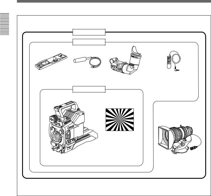
Product Configurations
The eight models, DXC-D35K, DXC-D35L/D35WSL, DXC-D35H, DXC-D35PK, DXC-D35PL/D35WSPL, and DXC-D35PH, comprise both NTSC and PAL
versions and the components as shown in the figure on next page. The operation of the basic camera unit is the same in all cases.
Chapter 1 Overview |
7 |
Product Configurations
Overview1Chapter |
|
DXC-D35K/D35PK |
|
|
DXC-D35L/D35PL |
|
|
|
|
|
|
|
VCT-U14 Tripod |
Microphone |
RM-LG1 Remote Control Unit |
|
Adaptor |
|
|
|
|
DXF-801/801CE Viewfinder |
|
|
|
|
|
|
|
DXC-D35H/D35PH |
|
|
|
|
Test chart for flange |
|
|
|
focal length |
|
|
|
adjustment |
|
DXC-D35/D35P/D35WSa)/ |
VCL-918BY |
|
|
D35WSP a) Camera Headb) |
||
|
Zoom Lens |
||
|
|
|
|
a) |
DXC-D35WSL/D35WSPL only |
|
|
b) |
Illustration: DXC-D35WS/D35WSP |
|
|
Camera adaptor
The product kit does not include a camera adaptor: to use a camera adaptor, you will need to purchase a model CA-537/537P or CA-327/327P.
8 |
Chapter 1 Overview |

Features
Features on the DXC-D35/D35P/
D35WSL/D35WSPL
The DXC-D35WSL/S35WSPL is a 16:9 wide-screen type (4:3-16:9 switchable) digital video camera while the DXC-D35/D35P is a 4:3 standard-screen type digital video camera. Common features on both types are described in this section. See also “Features on the DXC-D35WSL/D35WSPL” ( page 12) for using the DXC-D35WSL/S35WSPL.
2/3-inch IT type Power HAD (WS) CCD
The DXC-D35/D35P Color Video Camera uses 2/3- inch IT type Power HAD CCDs. (For the DXCD35WSL/D35WSPL, Power HAD WS CCDs are used. ) It outperforms most of the exiting FIT type CCD cameras for high-end use, in both picture quality and sensitivity.
•Smear: –125 dB (DXC-D35/D35P) or –120 dB (DXC-D35WSL/D35WSPL)
•Sensitivity: F11.0 (at 3200 K, 2000 lux)
•S/N: 63 dB (DXC-D35/D35WSL) or 61 dB (DXCD35P/D35WSPL)
Sophisticated image processing
TruEye™ processing makes possible the following performance features. This new digital signal processing has brought reproduction of natural colors to the level achieved by the human eye.
DynaLatitude™
Enables detailed adjustment of contrast control in each pixel in accordance with a histogram of luminance signal levels (see page 45).
DCC+ (dynamic contrast control plus)
Prevents white breakup when shooting a high intensity subject, and also prevents color faults in high intensity subject.
Black stretch and compress
Enables control of luminance signal levels in black areas without changing the hue.
Variety of detail corrections
•Skin detail function: this function gives a slightly softer appearance to the subject’s face. The target skin color can be automatically set.
•Black halo correction
•Red/green vertical detail correction: this function performs vertical detail compensation for both red and green signals.
•Horizontal detail frequency control
Recording and managing setup data
In addition to the setup menu that is displayed in the viewfinder screen, the DXC-D35/D35P/D35WSL/ D35WSPL is equipped with the following functions to facilitate camera head setup.
Setup file system
You can use setup files when making adjustments or settings. The DXC-D35/D35P/D35WSL/D35WSPL comes with factory preset files that contain shipped settings and you can freely create user files as well.
Automatic recording of setup data (when using DSR-1/1P)
When the DXC-D35/D35P/D35WSL/D35WSPL is connected to the DSR-1/1P VTR, two types of setup data can be recorded.
SetupLog™: Shooting-related environment settings are recorded onto the tape at intervals of a few seconds. This recorded data can then be used to reproduce the same shooting conditions in subsequent shots. It also makes it easier to identify the causes of problems in previous shots.
SetupNavi™: The setup conditions selected with the setup menu and setup files are recorded onto the tape. The recorded setup data can be copied to other camera heads so that the same setup can be shared among several camera heads.
Overview 1 Chapter
Chapter 1 Overview |
9 |

Features
|
|
ClipLink™ Function (when using DSR- |
|
|
|
|
||
|
||
|
|
1/1P) |
|
||
|
||
|
||
|
||
|
|
The ClipLink function can be used at every step from |
|
|
|
|
|
|
|
|
|
|
|
|
|
|
|
|
||
|
||
|
||
|
|
acquisition to editing. Information necessary for |
Chapter |
|
|
|
editing is recorded when shooting to ensure fast and |
|
|
|
|
1 |
|
efficient editing operations. |
|
When you set a recording start (Rec IN) point or when |
|
Overview |
|
|
|
you press the TAKE button to set a Mark IN point, the |
|
|
|
|
|
|
video image at that point is recorded on the tape in |
|
|
compressed form as an Index Picture. In addition, the |
|
|
time codes for such editing points (Mark IN/Mark |
|
|
OUT points or cue points) are recorded along with |
|
|
other editing point data (such as the cassette number |
|
|
and scene number) into cassette memory (as ClipLink |
|
|
log data). Unsuccessful scenes containing faults can |
|
|
also be marked in cassette memory as “NG”, so that |
|
|
only the good scenes are taken up from cassette |
|
|
memory when editing. |
|
|
|
|
|
Dockable with various types of VTRs |
|
|
The DXC-D35/D35P/D35WSL/D35WSPL docks with |
|
|
the DSR-1/1P DVCAM VTR to configure a digital |
|
|
camcorder. It also docks with the PVV-3/3P Betacam |
|
|
SP VTR to configure a Betacam SP camcorder. In |
|
|
addition, the DXC-D35/D35P/D35WSL/D35WSPL |
|
|
docks with the EVV-9000/9000P Hi-8 VTR. Using an |
|
|
adaptor (not supplied), it is also able to dock with a |
|
|
variety of existing S-VHS VTRs. |
|
|
|
|
|
New Functions boost operability |
|
|
EZ (easy) mode function |
|
|
When there isn’t time to check the camera head |
|
|
settings, simply press the EZ mode button to start the |
|
|
auto adjustment function using standard settings. |
|
|
There is no need to lose a shot for lack of setup time. |
|
|
EZ (easy) focus |
|
|
Press the EZ focus button before shooting to ensure a |
|
|
quick and accurate focus. |
Programmable gain
The amount of gain relative to the GAIN switch setting (H, M, or L) can be programmed as –3 dB, 0 dB, 3 dB, 6 dB, 9 dB, 12 dB, 18 dB, 18 dB+DPR1), 24 dB,
24 dB+DPR and hyper gain.
Hyper gain
Hyper gain (36 dB or 42dB, i.e. about 60 times or 120 times greater than
0 dB) can be easily set via one switch setting. This can also be done from remote equipment.
Auto tracing white balance
This function automatically traces the white balance, which constantly changes as lighting conditions change. Auto tracing white balance is especially useful when there is no time to manually adjust the white balance or when shooting moves between indoor and outdoor locations.
Total level control system (TLCS)
Even if the incoming light exceeds the range in which the standard auto iris can control exposure, the auto gain control (AGC) or auto exposure (AE) backs up to ensure proper exposure.
Dual pixel readout (DPR)
When the gain is set to either 18 dB or 24 dB, the gain setting can be doubled (6 dB up) without increasing the noise level.
Recording time display
Recording time can be displayed in either of the following modes.
•Total recording time for all cuts
•Total recording time for current cut
Viewfinder super detail
Video signals for the viewfinder are mixed with DTL signals to make focusing easier.
..........................................................................................................................................................................................................
1) DPR = Dual Pixel Readout
10 Chapter 1 Overview
Dual zebra pattern display
Two types of zebra patterns, zebra 1 and zebra 2 can be displayed simultaneously or independently. The zebra 1 can be set to the levels ranging from 70 to 90 IRE on the DXC-D35/D35WSL (or from 70 to 90% on the DXC-D35P/D35WSPL) and the zebra 2 indicates the levels of 100 IRE for the DXC-D35/D35WSL or more (or the levels of 100% or more for the DXCD35P/D35WSPL).
Color temperature display
When reading the white balance, the color temperature is displayed on the viewfinder screen.
Switching the color temperatures for the preset white balance
You can select the preset white balance at 3200 K (default) or 5600 K (default) by setting the FILTER control. The preset white balance can be changed to other value through menu setting (see page 59).
Video monitor output with text
The video signal with text superimposed that is shown in the viewfinder can also be output to an external video monitor.
Camera head microphone output indicator
An indication 9 appears in the viewfinder whenever a signal is being output from the camera head’s microphone.
1-kHz reference signal output
Along with a color bar, a 1-kHz reference signal can also be output.
Freeze mix function (when using DSR-1/1P)
The freeze mix function superimposes any previously recorded still picture on the viewfinder screen to facilitate framing the subject when reshooting the scene.
Edit Search Function (when using DSR-1/1P)
When using the DXC-D35/D35P/D35WSL/D35WSPL with the DSR-1/1P, pressing the EDIT SEARCH buttons allow the tape to play back in search mode. Set either of two playback speeds.
Designed for ease of operation
Dynafit Pad
Thanks to the Dynafit Pad which fits well to the shoulder, the camera is stable on the shoulder.
Slide cover
The slide cover can hide the switches and buttons that are seldom used during shooting. The cover can be locked so as not to open during shooting.
High-performance viewfinder (DXF-801/ 801CE)
•High resolution (600 TV lines of horizontal resolution)
•Large-diameter eye cup for easier viewing and focusing
•PEAKING potentiometer for vertical and horizontal detail control
•Two indicators can be used as TALLY indicators.
•Tough die-cast aluminum body
•DISPLAY switch that can turn the character display on and off
•Light that can light the lens control elements
•Switching the aspect ratio automatically between 16:9 (wide screen) and 4:3 (standard screen) when used with the DXC-D35WSL/D35WSPL
VTR data display
When connected to a VTR, the DXC-D35/D35P/ D35WSL/D35WSPL is able to display the following data on the viewfinder screen.
•Time values (counter, time code, or user bit vales)
•VTR audio levels
•Remaining tape time
•VTR operation mode
•Remaining battery capacity (when using an Anton Bauer Intelligent Battery System)
•ClipLink information (when using the DSR-1/1P)
Overview 1 Chapter
Chapter 1 Overview 11

Overview 1 Chapter
Features
Features on the DXC-D35WSL/
D35WSPL
Features only on the DXC-D35WSL/S35WSPL is described in this section. See “Features on the DXCD35/D35P/D35WSL/D35WSPL” (page 9) for common features on a 4:3 standard-screen type digital video camera and 16:9 wide-screen type digital video camera.
Switchable between 16:9 and 4:3 aspect ratios
A simple menu operation provides instant switching between the 16:9 and 4:3 aspect ratios. In 4:3 mode, a screen equivalent to a 4:3 screen is obtained through digital processing of the 16:9 video signals produced by the WS CCD. (See page 68.)
Wide-aspect ID signals
A menu setting is available to add wide-aspect ID signals1) to 16:9-mode video signals.2) (See page 68.)
Selection of the safety zone size in 16:9 mode
When the aspect ratio is 16:9, you can change the safety zone size through menu setting (see page 65.)
..........................................................................................................................................................................................................
1)ID signals complying with EIAJ CPR-1204 (DXCD35WSL) or complying with ETS WSS (DXCD35WSPL).
2)Video signals refer to the following:
•Video signals output from the VIDEO OUT connector and MONITOR OUT connector.
•The Y component of Y/C separate signals and the Y component of component signals output from the VTR connector.
12 Chapter 1 Overview
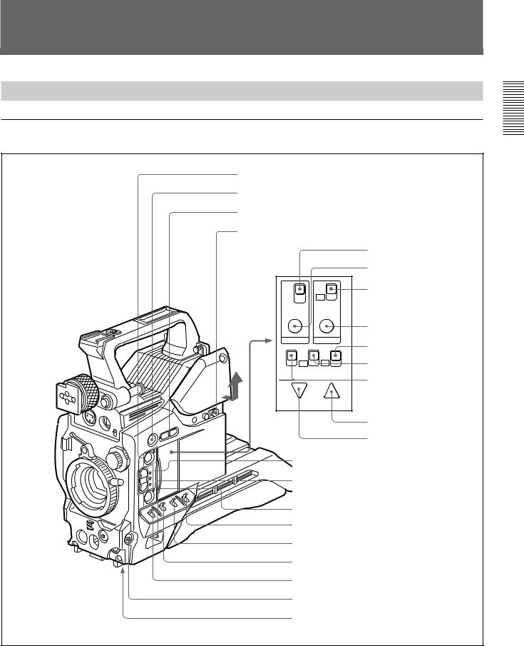
Location and Function of Parts
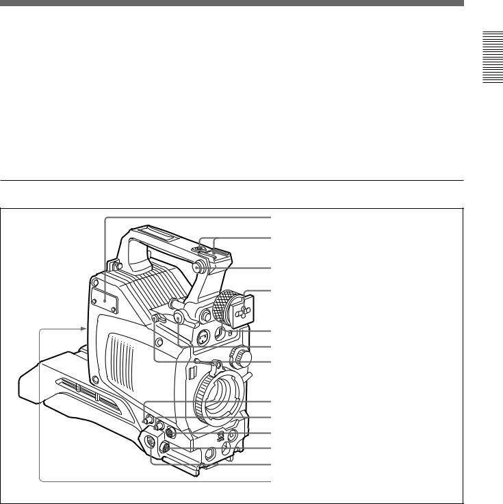
Camera Head
Right side view
1 EZ MODE button and indicator
2 EZ FOCUS button
3 EDIT SEARCH buttons
4 Slide cover lock
TTL |
ON |
|
DUR |
OFF |
|
OFF |
||
|
||
TTL RESET |
SET |
REC TIME |
SKIN DTL |
||
ON |
ON |
|
FILE |
OFF |
OFF |
|
STD |
ZEBRA |
HYPER |
SETUP |
|
|
|
GAIN |
|
DOWN/OFF UP/ON
qf REC TIME switch qg TTL RESET button
qh SKIN DTL switch
qj SKIN DTL SET button
qk SET UP switch
ql HYPER GAIN switch w; ZEBRA switch
wa UP/ON button
ws DOWN/OFF button
5 A.IRIS MODE switch and indicator
6 ATW button and indicator
7 POWER switch
8 MENU/STATUS switch
9 W. BAL switch
q; OUTPUT/DL/DCC+ switch
qa GAIN switch qs NG button
qd Breaker switch
Illustration: DXC-D35WS/D35WSP
Overview 1 Chapter
Chapter 1 Overview 13

Location and Function of Parts
1 EZ (“easy”) MODE button and indicator
Depress this button (EZ mode on) when you want to be able to shoot immediately, with automatic adjustment of the camera settings to standard values. (See page 68.) When this function is used, the iris and
1Chapter |
the white balance are adjusted automatically. (The |
||
|
|||
|
total level control system functions.) Press this button |
||
Overview |
again to return the camera to the previous settings (EZ |
||
mode off). |
|||
|
|||
|
|
||
|
Note |
|
|
|
When connecting the CCU-M5/M7 (or CCU-M5P/ |
||
|
M7P) Camera Control Unit or the RM-M7G Remote |
||
|
Control Unit, the “easy mode” function is disabled. |
||
|
2 EZ FOCUS button |
||
|
Press this button to turn the “easy focus” function on. |
||
|
This opens the iris, to make it easier to focus before |
||
|
beginning shooting. The indication “EZ FOCUS” |
||
|
appears in the viewfinder while the function is on; to |
||
|
turn it off, press the EZ FOCUS button again. If left |
||
|
on, the function automatically turns off after about ten |
||
|
seconds. |
||
|
|
||
|
Note |
|
|
|
If the “easy focus” function is still on when you press |
||
|
the VTR button, it turns off automatically and |
||
|
recording starts about one second later. |
||
|
3 EDIT SEARCH buttons (for operation with |
||
|
DSR-1/1P) |
||
|
When using the DSR-1/1P to record, you can see the |
||
|
search playback while pressing either of these buttons |
||
|
at recording pause mode to quickly find the next |
||
|
recording start point. Two playback speeds are |
||
|
available, and press either of the buttons to the inner |
||
|
position to increase the speed. |
||
|
4 Slide cover lock |
||
|
This lock keeps the slide cover closed. |
||
|
|
||
|
Pull the upper panel forward and then lift it up. |
||
EDIT SEARCH |
LOCK |
FREE |
EDIT SEARCH |
LOCK |
FREE |
Unlocked position Locked position
5 A.IRIS (auto iris) MODE switch and indicator
When you use the auto iris function (by setting the iris selector on the lens to A), set this switch to suit the shooting conditions. Selecting BACK L gives more light to back-lit subjects, and selecting SPOT L adjusts for high contrast in spot-lit subjects. For normal shooting, set this switch to STD.
6 ATW (auto tracing white balance) button and indicator
Press this button, turning the indicator on, when you want the white balance to be adjusted automatically to follow changes in lighting conditions. (See page 81.)
7 POWER switch
This powers the camera on and off. There are two different ON settings as follows.
ON STBY: This puts the VTR on standby. In this state, pressing the VTR button on the camera head, the lens or a camera adaptor starts recording immediately.
ON SAVE: This puts the VTR in the power-saving state, with the video head drum stationary. In this state, it takes a few seconds to start recording after pressing the VTR button.
Note
The VTR state when this switch is in the ON STBY or ON SAVE position may depend on the VTR model.
8 MENU/STATUS switch
When you press this switch to the MENU position, the basic menu is displayed. Keep pressing it to the MENU position to cycle through the various menu displays. When you press the switch to the STATUS position, the DXC-D35/D35P/D35WSL/D35WSPL’s status (of current settings) is displayed.
9 W. BAL (white balance) switch
This selects the white balance setting from the preset value, the value in memory A or the value in memory B. (See page 79.)
0 OUTPUT/DL/DCC+ (DynaLatitude/dynamic contrast control plus) switch
Use this switch to select the DCC+ function, the DynaLatitude function, or color bar output. Select the CAM/DCC+ position in most cases.
CAM/DCC+: This activates the DCC+ function. This prevents color faults when shooting highintensity subjects.
14 Chapter 1 Overview

CAM/DL: This setting uses the DynaLatitude function, which finely adjusts the contrast of each pixel according to a histogram of luminance signal levels. Access advanced menu page 2 to set the DynaLatitude function ON or OFF. The DynaLatitude effect can be set to any of three levels, Low, STD (standard), and High with basic menu page 2.
BARS: This setting displays color bars.
For details of menu operation, see Chapter 4 “Viewfinder Screen Displays and Menus” (page 51).
qa GAIN switch
This selects one of the three gain settings, high, medium or low. You can choose the gain values assigned to the H, M and L settings from values from –3 dB to 24 dB + DPR and HYPER GAIN.(See page 64.) The factory default selections are 18 dB (H), 9 dB
(M) and 0 dB (L).
Note
When the HYPER GAIN switch ql is in the ON position, the GAIN switch has no effect.
qs NG button
When using the ClipLink function during shooting, you can designate a particular scene as “NG” (No Good) by pressing this button before shooting the next scene. Press the button again to cancel the NG setting.
qd Breaker switch
If there is a fault in the camera power supply, the breaker trips, and the camera power supply is disconnected. Correct the fault in the power supply, then press this switch.
qf REC (recording) TIME switch
This selects the recording time indication in the viewfinder.
TTL: Displays the total recording time.
The total recording time is not reset even when you stop the VTR and power off the camera, for example, to replace the battery pack.
DUR: Displays the recording time of the current cut. OFF/TC: Switches off the recording time display.
If, however, a PVV-3/3P is connected, and in the advanced menus you set the time code display item (TC IND) to ON (see page 67), then the VTR time data (time code, CTL count, or user bit value) is displayed.
Note
The recording time displayed when this switch is set to the TTL or DUR position is obtained by counting the duration of the internal reference signal input to the camera.
The value may not agree exactly with the value derived from the time code values. Furthermore, the value displayed may not be correct when another manufacturer’s VTR is connected to the camera.
qg TTL (total) RESET button
Pressing this button resets the total recording time (TTL selection) to zero.
qh SKIN DTL (skin detail) switch
Set this switch to ON to use the skin detail correction function.
For details, see “Skin Detail Correction” (page 93).
qj SKIN DTL (skin detail set) SET button
Press this button with the SKIN DTL button qh to display the area detect cursor on the viewfinder screen. Place the cursor on the target and press this button to perform skin detail correction.
For details, see “Skin Detail Correction” (page 93).
qk SET UP switch
Use this switch to select the camera head setup method.
STD: Set up using the setup menu. Setup file data is not displayed.
FILE: Set up using setup files and the setup menu.
ql HYPER GAIN switch
Setting this switch to the ON position increases the gain by a factor of about 60 or 120 with respect to 0 dB (a 30 or 36 dB increase by electronic amplification and a 6 dB increase for DPR, bringing about a total gain increase of 36 or 42 dB).
When this switch is in the ON position, the indication “HYPER” appears in the viewfinder, and the GAIN UP indicator in the viewfinder also lights.
When finished shooting, return this switch to the OFF position. The “HYPER” indication disappears and the GAIN UP indicator goes out.
Note
Increasing the gain with this switch reduces the horizontal resolution by 50%.
Overview 1 Chapter
Chapter 1 Overview 15
Overview 1 Chapter
Location and Function of Parts
|
|
w; ZEBRA switch |
wa UP/ON button |
Set this switch to the ON position to display a zebra |
Use this button to open displays and to make “ON” |
pattern (diagonal stripes) in the viewfinder. |
settings. When using the advanced menus, use this |
Depending on the zebra setting in advanced menu page |
button to change menu pages or to switch to the |
4 (page 65), the zebra 1 for video levels between 70 to |
ordinary screen display. |
90 IRE (or 70 to 90%) and the zebra 2 for video levels |
|
100 IRE or more (or 100% or more) can be displayed |
ws DOWN/OFF button |
independently or simultaneously. |
Use this button to close displays and to make “OFF” |
|
settings. You can also use this button to change menu |
|
pages when using the advanced menus. |
Front view
1 MIC IN +48 V connector
2 VF connector
3 MIC LOW CUT switch
4 FILTER control
5 Lens mount
6 SHUTTER switch
7 TAKE button
8 AUDIO LEVEL knob
9 WHT/BLK switch
0 VTR button
Illustration: DXC-D35WS/D35WSP
1 MIC (microphone) IN +48 V connector (XLR 3- pin, female)
Connect the supplied microphone or an optional microphone (operable with a 48 V supply).
2 VF (viewfinder) connector (20-pin)
This is the connector for the DXF-801/801CE viewfinder.
Note
When using this connector, do not connect a DXF-41/ 51 viewfinder to the VF connector on the left side.
3 MIC LOW CUT switch
Set this switch to the ON position to insert a high-pass filter in the microphone circuit, reducing wind noise. Normally leave the switch in the OFF position.
4 FILTER control
Select the color temperature conversion filter appropriate to the lighting conditions. (See page 43.)
5 Lens mount
Attach the zoom lens here.
16 Chapter 1 Overview
6 SHUTTER switch
Use this switch to set the shutter speed, CLS (clear scan), or EVS setting (see page 84). Usually, set this switch to OFF.
7 TAKE button
Press this button to specify an editing point (Mark IN/ OUT or cue point) at the current tape position during shooting.
8 AUDIO LEVEL knob
When the DSR-1/1P is attached, you can use this knob to manually adjust the channel 1 audio recording level.
9 WHT/BLK (white/black) switch
This switch is used for automatic adjustment of the white balance and black balance. (See pages 79 to 83.)
0 VTR button
Pressing this button starts and stops recording on the VTR.
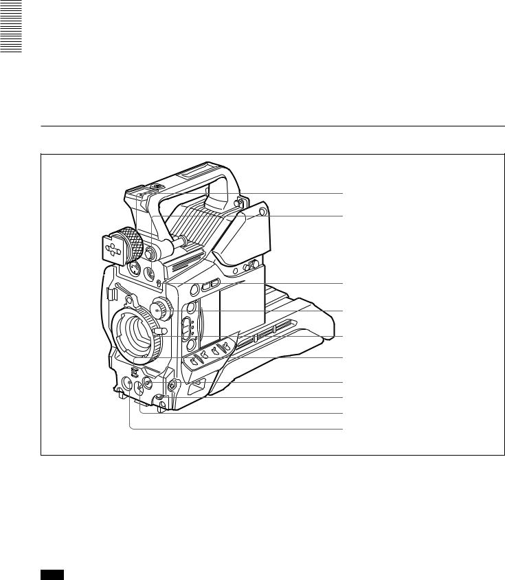
Left and upper view
1 Fitting for optional microphone holder |
2 Accessory fitting shoe and screw hole |
3 Shoulder strap fitting |
4 Viewfinder fitting shoe |
5 Viewfinder left-to-right positioning ring |
6 Viewfinder front-to-back position locking lever |
7 REMOTE connector 1 |
8 MONITOR OUT connector |
9 VIDEO OUT connector |
0 REMOTE connector 2 |
qa LENS connector |
qs VF connector |
qd VTR connector |
1 Fitting for optional microphone holder
You can fit an optional CAC-12 Microphone Holder here. (See page 33.)
2 Accessory fitting shoe and screw hole
Attach optional video lights or other accessories here.
3 Shoulder strap fixture
To use the supplied shoulder strap, fix one end here and the other end to the VTR.
4 Viewfinder fitting shoe
Fix the DXF-801/801CE Viewfinder here.
5 Viewfinder left-to-right position fixing ring
Loosen this ring to adjust the left-to-right position of the viewfinder. (See page 32.)
6 Viewfinder front-to-back position locking catch
Release this catch to adjust the front-to-back position of the viewfinder. (See page 32.)
Overview 1 Chapter
Chapter 1 Overview 17

Overview 1 Chapter
Location and Function of Parts
7 REMOTE connector 1 (mini-jack)
Connect the RM-LG1 Remote Control Unit to enable remote operation of the ClipLink function.
8 MONITOR OUT connector (BNC)
Outputs both the camera video and the character information as displayed on the viewfinder screen. You can connect an optional LCD color monitor to this connector.
9 VIDEO OUT connector (BNC)
This outputs the video signal captured by the camera.
0 REMOTE connector 2 (10-pin)
Connect the optional RM-M7G Remote Control Unit to this connector. Set the CAMERA HEAD SELECT switch on the bottom of RM-M7G to 1.
Note
When using the RM-M7G, note the following points.
•When operating the camera head from the camera control unit, connect the RM-M7G to the camera control unit.
•EZ mode cannot be used if the RM-M7G is connected to the camera head.
qa LENS connector (12-pin, for 2/3-inch lens)
Connect the lens connector.
qs VF (viewfinder) connector (8-pin)
This is the connector for the DXF-41/51 viewfinder.
Note
When using this connector, do not connect a DXF-801/ 801CE viewfinder to the VF connector on the front of the camera head.
qd VTR connectors (PRO 76-pin DIGITAL and PRO 50-pin)
Connect a dockable VTR. A PRO 76-pin DIGITAL connector is for the DSR-1/1P and a PRO 50-pin connector is for the PVV-3/3P or a camera adaptor.
18 Chapter 1 Overview
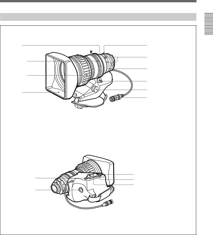
VCL-918BY Zoom Lens
1 Iris ring |
4 M button |
|
5 F.B adjustment ring |
2 Zoom ring |
and F.B fixing screw |
6 MACRO ring
3 Focus ring
|
7 ZOOM selector |
|
Lens hood |
8 Zoom remote control |
|
connector |
||
|
||
|
9 Lens connector |
|
qs Instant automatic iris adjustment |
0 RET button |
button |
qd IRIS selector
qf Motorized zoom lever
qa VTR button
Overview 1 Chapter
Chapter 1 Overview 19

Overview 1 Chapter
Location and Function of Parts
1 Iris ring
For manual iris control, set the IRIS selector qd to the “M” position, and turn this ring.
2 Zoom ring
For direct manual zoom control, set the ZOOM selector 7 to the “MANU.” position, and turn this ring.
3 Focus ring
Turn this ring to focus the lens on the subject.
4 M (close-up) button
For close-up work, turn the MACRO ring 6 while holding this button down. (See page 91.)
5 F.B (flange focal length) adjustment ring and F.B fixing knob
F.B adjustment ring : To adjust the flange focal length, loosen the F.B fixing knob, then turn the ring. (See page 89.)
F.B fixing knob: Fixes the F.B adjustment ring.
6 MACRO (close-up) ring
For close-up, turn this ring while holding the M button 4 down. (See page 91.)
7 ZOOM selector
This selects the mode of zoom operation. SERVO: power zoom
MANU. (manual): manual zoom
8 Zoom remote control connector (8-pin)
Connect the optional LO-26 lens remote control unit for remote control of zooming.
9 Lens connector (12-pin)
Connect to the LENS connector (qa on page 18) of the Camera Head.
0 RET (return) button
This allows you to check the video signal as follows.
When operating with a portable VTR connected via other equipment: when the VTR is in
recording, pressing this button connects the E-E video signal1) from the VTR to the viewfinder.
When operating with a DSR-1/1P or PVV-3/3P mounted on the camera head: when the VTR is in
recording pause mode, press this button to review the last few seconds of the recording in the viewfinder (recording review).
When operating with a CCU-M5/M5P/M7/M7P Camera Control Unit connected: pressing this
button connects the return video signal from the camera control unit to the viewfinder.
When this button is not pressed, the viewfinder displays the video signal captured by the camera.
qa VTR button
When operating with a VTR: this button starts and stops recording, and once more to stop.
When operating with a CCU-M5/M5P/M7/M7P Camera Control Unit connected: pressing this
button connects the return video signal from the camera control unit to the viewfinder.
(Starting and stopping recording is controlled on the VTR.)
qs Instant automatic iris adjustment button
While using manual iris control, press this button to switch temporarily to the automatic iris control setting. The automatic setting is maintained as long as you hold the button down.
qd IRIS selector
This selects the mode of iris operation. (See page 14.)
A (automatic): automatic iris M (manual): manual iris
qf Motorized zoom lever
Use this to carry out a power zoom. Pressing the lever harder increases the zoom speed.
W end: zoom toward wide angle T end: zoom toward telephoto
..........................................................................................................................................................................................................
1)E-E video signal: “electric-to-electric” video signal. This is the input video signal which has passed through internal electrical circuits, but has not been converted to a magnetic signal.
20 Chapter 1 Overview
DXF-801/801CE Viewfinder
You can switch the scan size of the DXF-801/801CE in accordance with the aspect ratio selected on the camera or camcorder.
1 Eyepiece focusing knob
2 Stopper
Microphone holding screw
Microphone holder
Microphone
3 LIGHT switch and light
HIGH LOW OFF
LIGHT 
4 TAKE/TALLY indicator
 TALLY
TALLY 
TAKE REC BATT
5 BATT indicator
6 REC/TALLY indicators
7 GAIN UP indicator
SHUTTER |
GAIN UP |
8 SHUTTER indicator
Eye cup
9 PEAKING control
0 CONTRAST control qa Tally lamp
qs BRIGHT control
 qd Eyepiece release catch
qf TALLY switch
qg DISPLAY switch
qh Viewfinder connector
Overview 1 Chapter
1 Eyepiece focusing knob
Turn this to adjust the viewfinder focus to match your eyesight. (See page 88.)
2 Stopper
Lift up when detaching the viewfinder (See page 32).
3 LIGHT switch and light
The light lights the lens and the switch controls the light as follows.
HIGH/LOW: Turn the light on and control the brightness.
OFF: Turns the lights off.
4 TAKE/TALLY indicator (orange)
When using the ClipLink function while shooting, this indicator lights when the TAKE button (7 on page 17) has been pressed to set a Mark IN point and goes out when a Mark OUT point is set.
5 BATT (battery) indicator (red)
This lights when the battery capacity is low.
Note
When using a camera control unit, this indicator flashes when
you operate the controls, but this is not a malfunction.
Chapter 1 Overview 21

Overview 1 Chapter
Location and Function of Parts
6 REC/TALLY (recording/tally) indicators (red)
•This flashes from the time when you press the VTR button (0 on page 17 and qa on page 20) on the lens or camcorder until recording starts, then stays on continuously during recording.
•When using a camera control unit, this lights when the video from the camera is selected.
•This is also used to indicate a fault. (See page 97.)
•The lower indicator can be disabled by menu setting.
(See page 66.)
7 GAIN UP indicator (orange)
This lights when the gain is 3 dB or more.
8 SHUTTER indicator (red)
This lights when the SHUTTER switch (6 on page 17) is in the ON position. (If the EVS is selected, the indicator will not light.)
9 PEAKING control
This adjusts the outline intensity of the viewfinder image. (See page 88.)
0 CONTRAST control
This adjusts the contrast of the viewfinder image. (See page 88.)
qa Tally lamp
When the TALLY switch qf is in the ON position, this operates in the same way as the REC/TALLY indicators 6.
qs BRIGHT (brightness) control
This adjusts the brightness of the viewfinder image.
(See page 88.)
qd Eyepiece release catch
To view the viewfinder screen directly, press this catch, and hinge up the eyepiece.
qf TALLY switch
Set this switch to the ON position to use the tally lamp qa.
qg DISPLAY switch
Set this switch to OFF when you want to remove the character data from the viewfinder and the monitor connected to the MONITOR OUT connector. However, items which are set to OFF in advanced menu page 5 and page 6 are not displayed even when this switch is set to ON.
qh Viewfinder connector (20-pin)
Connect this to the VF connector (2 on page 16).
22 Chapter 1 Overview

Chapter2
Fitting and
Connections
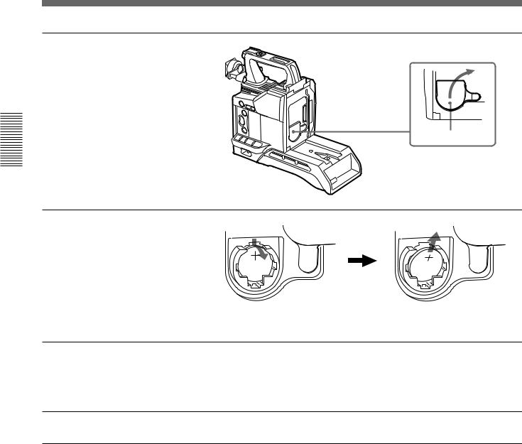
Replacing the Lithium Battery
The camera head uses a lithium battery (CR2032) to retain date and time data.
When the lithium battery’s voltage falls, the clock indication dose not appear. Replace the lithium battery and set the clock (see page 86).
Notes
•Carefully read the instructions for replacing the lithium battery. Lithium batteries may explode if misused.
•Use only CR2032-type lithium batteries. Other types of lithium batteries may come loose when the camcorder is moved. If you have difficulty finding CR2032-type lithium batteries, contact your Sony dealer.
Chapter 2 Fitting and Connections |
23 |
Replacing the Lithium Battery
Connections and Fitting 2 Chapter
1 Pull the upper part of the battery cover (on the rear of the camera head) forward and turn the cover clockwise.
For detaching the VTR or camera adaptor, see “Fitting a VTR” next page.
 Rear of the
camera head
Battery cover
2 Take out the lithium battery.
Press down and pull out toward you.
3 Reverse step 2 to insert a replacement lithium battery. Make sure that the + symbol on the battery is facing you.
4 Close the battery cover.
24 |
Chapter 2 Fitting and Connections |
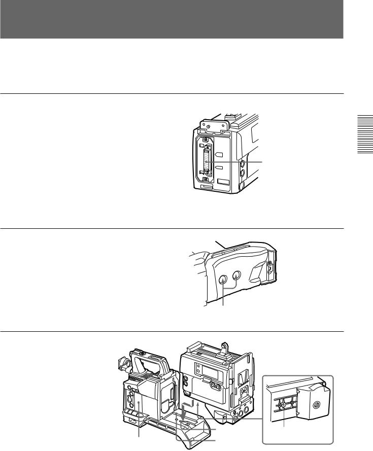
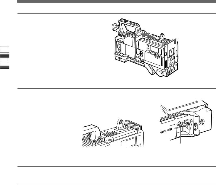
Fitting a VTR
|
|
This section explains how to attach the DSR-1/1P to |
When replacing the camera head grip with a camcorder |
the camera head. The method for attaching a PVV-3/ |
grip, see “Using the Camcorder Grip” (page 27). |
3P is similar. |
|
1 Set the PRO 76-pin DIGITAL connector on the DSR-1/1P. (The camera connector on the PVV-3/3P is PRO 50-pin.)
For details, see the operating instructions for the DSR-1/1P.
DSR-1/1P
Camera connector (PRO 76-pin DIGITAL)
2 Loosen the two screws and remove the shoulder pad.
Screws
3 Align the projection on the bottom of the DSR-1/1P with the slot on the camera head.
|
Slot |
Projection |
Camera head |
Groove |
|
(continued)
Connections and Fitting 2 Chapter
Chapter 2 Fitting and Connections |
25 |
Connections and Fitting 2 Chapter
Fitting a VTR
4 Slide the DSR-1/1P and the camera head together in the groove as far as possible.
5 Tighten the two screws in the grip connector and the two screws in the shoulder pad section.
Screws
6 Attach the shoulder pad.
To remove the VTR |
To fit a camera adaptor |
Reverse the fitting procedure. |
Follow the same procedure as when fitting a VTR. |
26 |
Chapter 2 Fitting and Connections |
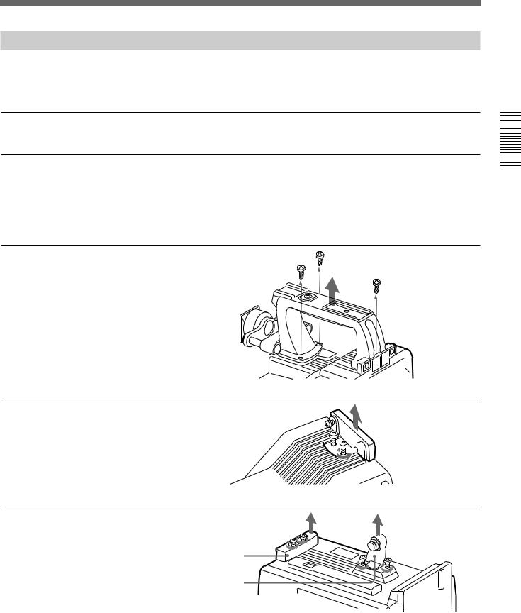
Using the Camcorder Grip
When using the camera head with a VTR as a |
camcorder grip and the method for attaching it differ |
camcorder, you can replace the camera head’s grip |
slightly depending on the type of VTR. |
with a camcorder grip (not supplied). The type of |
|
Attaching a camcorder grip to the DSR-1/1P
1 If the viewfinder is attached, adjust the viewfinder to the full-forward position.
For details, see “Adjusting the viewfinder position” on page 32.
2 Remove the camera head grip’s three screws, then pull up the grip to remove it.
3 Remove the VTR connection plate.


 VTR connection plate
4 Remove the DSR-1/1P’s shoulder strap fitting and the
camera head connection plate.
Camera head connection plate
Shoulder strap fitting
(continued)
Connections and Fitting 2 Chapter
Chapter 2 Fitting and Connections |
27 |
Fitting a VTR
Connections and Fitting 2 Chapter
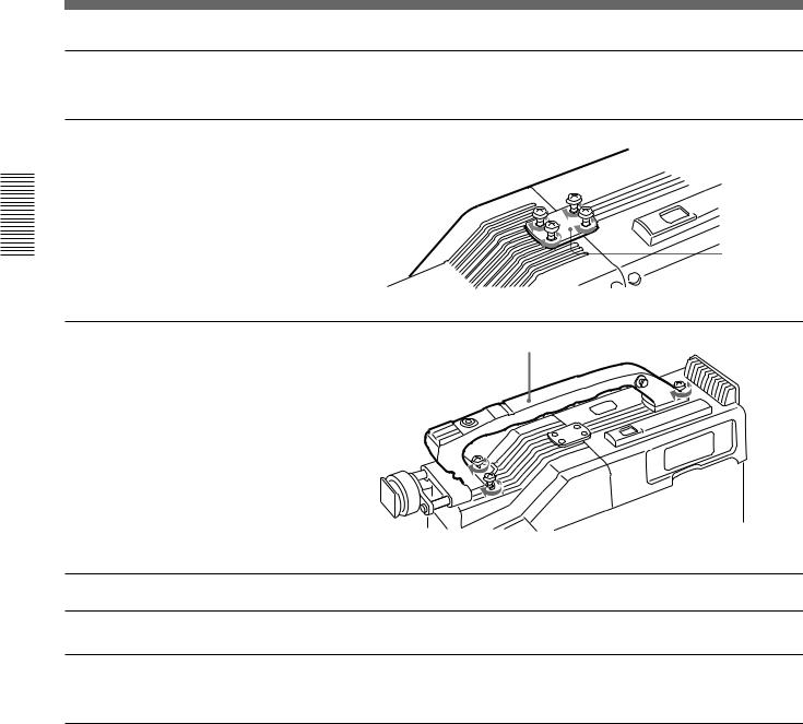
5 Perform the first three steps in “Fitting a VTR”.
6 Screw the connection plate (supplied with the grip for the DVCAM camcorder) which straddles the connection between the camera head and the DSR-1/1P. Also, tighten the two screws in the shoulder pad section. (See step 5 on page 26.)
Connection plate
7 Screw the grip for the |
Grip for the DVCAM camcorder |
DVCAM camcorder. |
|
Attaching a camcorder grip to the PVV-3/3P
1 Perform steps 2 to 4 in “Fitting a VTR”.
2 If the viewfinder is attached, adjust the viewfinder to the full-forward position.
For details, see “Adjusting the viewfinder position” on page 32.
28 |
Chapter 2 Fitting and Connections |
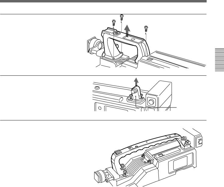
3 Remove the grip’s three screws, then pull up the grip to remove it.
4 Remove the PVV-3/3P’s
shoulder strap fitting.
Shoulder strap fitting
5 Screw the grip for the Betacam |
Grip for the Betacam |
|||||
camcorder. |
camcorder |
|
|
|
|
|
|
|
|
|
|
|
|
|
|
|
|
|
|
|
|
|
|
|
|
|
|
|
|
|
|
|
|
|
|
|
|
|
|
|
|
|
|
|
|
|
|
|
|
|
|
|
|
|
|
|
|
|
|
|
|
|
|
|
|
|
|
|
|
|
|
|
|
|
|
|
Connections and Fitting 2 Chapter
Chapter 2 Fitting and Connections |
29 |

Connections and Fitting 2 Chapter
Fitting the Lens
In the case of the DXC-D35K/D35PK model, the lens is already fitted. In other cases, use the following procedure to fit the lens.
1 Remove the retaining rubber which prevents the lens mount
from coming loose, then raise
the lens fixing lever, and Retaining rubber remove the lens mount cap.
Lens mount cap |
Lens fixing lever |
|
2 With the lens fixing lever turned fully counterclockwise, push in the lens, aligning the projection on the lens with the cutout on the camera.
Align and push in.
3 Supporting the lens, turn the lens fixing lever fully clockwise. Replace the retaining rubber on the lens mount.
30 |
Chapter 2 Fitting and Connections |
 Loading...