


HOBS |
|
||||||
USER INSTRUCTIONS |
|
|
|
GB |
|||
INSTRUKCJE |
|
||||||
UŻYCIA I MONTAŻU |
|
|
|
|
|
PL |
|
OCAK |
|
||||||
KULLANIM KLAVUZU |
|
|
|
|
TR |
||
ВАРОЧНЫЕ ПОВЕРХНОСТИ |
|
||||||
RU |
|||||||
ИНСТРУКЦИЯ ПОЛЬЗОВАТЕЛЯ |
|
||||||
|
|
||||||
PLITE |
|
||||||
MANUAL DE UTILIZARE |
|
|
RO |
||||
CANDY HOOVER GROUP S.R.L. • Via Privata Eden Fumagalli • 20047 Brugherio Milano Italy
|
CONTENT |
GB |
|
|
SPIS TREŚCI |
PL |
|
Safety Instructions ...................................................................... |
04 |
Instrukcje Bezpıeczeństwa ....................................................... |
08 |
||||
1. |
Instructions For The Installer ................................................. |
05 |
1. |
Instrukcje Dla Instalatora ........................................................ |
09 |
||
1.1. Bulding In ................................................................................ |
05 |
1.1 |
Zabudowa ................................................................................ |
09 |
|||
1.2. Suitable Location .................................................................... |
05 |
1.2 |
Odpowiednie Pomieszczenie ................................................... |
09 |
|||
2. |
Electrical Connection (For U.K. Only) .................................... |
05 |
2.1 |
Podłączenie Do Sieci Elektrycznej .......................................... |
09 |
||
2.1. Electrical Connection .............................................................. |
05 |
2.2 |
Podłączenie Do Gazu .............................................................. |
09 |
|||
2.2. Gas Connection (For U.K. Only).............................................. |
05 |
2.3 |
Przystosowanie Płyty Do Różnych Rodzajów Gazu ............... |
10 |
|||
2.3. Adapting The Hob To Different Types Of Gas ......................... |
06 |
2.4 |
Regulacja Płomienia Minimalnego ........................................... |
10 |
|||
2.4. Regulating The Minimum Flame.............................................. |
06 |
3. |
Użytkowanie Płyty - Instrukcje Dla Użytkownika .................. |
10 |
|||
3. |
Use Of Hob - User Instructions ............................................... |
06 |
3.1 |
Używanie Palników Gazowych ................................................ |
10 |
||
3.1. Using The Gas Burner............................................................. |
06 |
4. |
Czyszczenie I Konserwacja ..................................................... |
10 |
|||
4. |
Maintenance and Cleaning ...................................................... |
06 |
5. |
Obsługa Serwisowa ................................................................. |
11 |
||
5. Aftercare ................................................................................... |
06 |
6. |
Ochrona Środowiska ............................................................... |
11 |
|||
6. |
Protection Of The Environment .............................................. |
07 |
|
|
|
|
|
|
İÇİNDEKİLER |
TR |
|
|
СОДЕРЖАНИЕ |
RU |
........................................................................Güvenlik Uyarıları |
12 |
|
ПРАВИЛА ТЕХНИКИ БЕЗОПАСНОСТИ ............................................ |
17 |
||
1. |
Kurulum Talimatları ................................................................. |
13 |
1. |
Инструкции по выполнению установки ...................................... |
18 |
|
1.1. Ankastre Montaj ...................................................................... |
13 |
|
1.1. Встраиваемые варочные поверхности ......................................... |
18 |
||
1.2. Uygun Yer Tespiti .................................................................... |
13 |
|
1.2. Выбор места для установки варочной поверхности........................ |
18 |
||
2.1. Elektrik Bağlantısı ................................................................... |
13 |
2. |
Подключение к электросети (только для Великобритании) ......... |
18 |
||
2.2. Gaz Bağlantısı ......................................................................... |
13 |
2.1. Подключение к электросети ......................................................... |
18 |
|||
2.3. Ocağın Farklı Gaz Türlerine Uyarlanması .............................. |
13 |
2.2. Подключение к линии газоснабжения (только для Великобритании) 19 |
||||
2.4. Minimum Alevin Ayarlanması ................................................. |
13 |
2.3. Адаптация варочной поверхности на другие типы газа ................... |
19 |
|||
3. |
Ocak Kullanımı Kullanım Talimatları ..................................... |
13 |
2.4. Регулировка минимального пламени ............................................ |
19 |
||
3.1. Gazlı Ocak Gözlerinin Kullanımı ............................................ |
14 |
3. |
Инструкции по эксплуатации варочной поверхности................... |
19 |
||
4. |
Bakim Ve Temizlik ................................................................. |
14 |
3.1 использование газовой конфорки .................................................. |
19 |
||
5. |
Satış Sonrası Servis ................................................................ |
14 |
4. |
Обслуживание и чистка .............................................................. |
20 |
|
6. |
Çevrenin Korunması ............................................................... |
14 |
5. |
Послепродажное обслуживание ................................................. |
20 |
|
Garanti Belgesi ........................................................................... |
16 |
6. |
Защита окружающей среды ........................................................ |
20 |
||
|
CUPRINS |
RO |
1. |
Instrucţiuni de Instalare .......................................................... |
22 |
1.1. Incorporare .............................................................................. |
23 |
|
1.2. Amplasare................................................................................ |
23 |
|
2. |
Conexiunea electrică (numai pentru G.B.)............................. |
23 |
2.1. Conexiunea electrică .............................................................. |
23 |
|
2.2. Conectarea la gaz (numai pentru G.B.) .................................. |
23 |
|
2.3. Adaptarea la diverse tipuri de gaz ........................................... |
24 |
|
2.4. Reglarea flăcării minime .......................................................... |
24 |
|
3. |
Utilizarea plitei Instrucţiuni de utilizare ................................. |
24 |
3.1. Utilizarea arzătoarelor ............................................................. |
24 |
|
4. |
Întreţinere şi curăţare .............................................................. |
24 |
5. |
Service ...................................................................................... |
25 |
6. |
Protejarea mediului ................................................................. |
25 |
Gas Type Tables ...................................................................... |
26-27 |
|

Bracket
Figure 1
Figure 4
Seal
|
Min10 mm |
25a 45 mm |
|
|
accessible space |
Figure 2 |
Figure 3 |
Sp.da |
60 cm2 |
Figure |
5 |
|
120 cm2 |
|
240 cm2 |
180 cm2 |
|
|
INJECTOR |
|
A B |
C |
|
1/2 GAS CONICAL
Figure 6 |
Figure 7 |
 CYLINDRICAL
CONICAL
Figure 8
YES YES
Figure 10
03

SAFETY INSTRUCTIONS
WARNING: The appliance and its accessible parts become hot during use. Care should be taken to avoid touching heating elements.
•Children under 8 Year of age must be kept away from the appliance unless they are continuously supervised.
•This appliance can be used by children aged from 8 years and above and persons with reduced physical, sensory or mental capabilities or lack of experience and knowledge if they have been given supervision or instruction concerning use of the appliance in a safe way and understand the hazards involved.
•Children must not play with the appliance.
•Cleaning and user maintenance shall not be made by children without supervision.
WARNING: Unattended cooking on a hob with fat or oil can be dangerous and may result in fire.
NEVER try to extinguish a fire with water, but switch off the appliance and then cover flame e.g. with a lid or a fire blanket.
WARNING: Danger of fire: do not store items on the cooking surfaces.
WARNING:Accessible parts may become hot during use. Young children must be kept away.
•Do not use a steam cleaner for cleaning operations.
•Any spillage should be removed from the lid before opening.
•The hob surface must be allowed to cool down before closing the lid.
•This appliance is not intended to be operated by means of an external timer or separate remote-control system.
•The means for disconnection must be incorporated in the fixed wiring in accordance with the wiring rules.
•The instructions state the type of cord to be used, taking into account the temperature of the rear surface of the appliance.
•If the supply cord is damaged, it must be replaced by the manufacturer, its service agent or similarly qualified persons in order to avoid a hazard.
CAUTION: In order to avoid a hazard due to inadvertent resetting of the thermal cutout, this appliance must not be supplied through an external switching device, such as a timer, or connected to a circuit that is regularly switched on and off by the utility.
•This appliance must be installed in accordance with the regulations in force and only used in a well ventilated space. Read the instructions before installing or using this appliance.
•These instructions are only valid if the country symbol appears on the appliance. If the symbol does not appear on the appliance, it is necessary to refer to the technical instructions which will provide the necessary instructions concerning modification of the appliance to the conditions of use of the country.
•Prior to installation, ensure that the local distribution conditions (nature of the gas and gas pressure) and the adjustment of the appliance are compatible;
•The adjustment conditions for this appliance are stated on the label (or data plate);
•This appliance is not connected to a combustion products evacuation device. It shall be installed and connected in accordance with current installation regulations. Particular attention shall be given to the relevant requirements regarding ventilation.
•The use of a gas cooking appliance results in the production of heat and moisture in the room in which it is installed. Ensure that the kitchen is well ventilated: keep natural ventilation holes open or install a mechanical ventilation device (mechanical extractor hood). Prolonged intensive use of the appliance may call for additional ventilation, for example opening of a window, or more effective ventilation, for example increasing the level of mechanical ventilation where present.
04 GB
1. INSTRUCTIONS FOR THE INSTALLER
INSTALLING A DOMESTIC APPLIANCE CAN BE A COMPLICATED OPERATION WHICH IF NOT CARRIED OUT CORRECTLY, CAN SERIOUSLY AFFECT CONSUMER SAFETY. IT IS FOR THIS REASON THAT THE TASK SHOULD BE UNDERTAKEN BY A PROFESSIONALLY QUALIFIED PERSON WHO WILL CARRY IT OUT IN ACCORDANCE WITH THE TECHNICAL REGULATIONS IN FORCE. IN THE EVENT THAT THIS ADVICE IS IGNORED AND THE INSTALLATION IS CARRIED OUT BY AN UNQUALIFIED PERSON, THE MANUFACTURER DECLINES ALL RESPONSIBILITY FOR ANY TECHNICAL FAILURE OF THE PRODUCT WHETHER OR NOT IT RESULTS IN DAMAGE TO GOODS OR INJURY TO INDIVIDUALS.
1.1 BUILDING IN
The hob may be installed in any worktop which is heat resistant to a temperature of 100°C, and has a thickness of 25-45 mm. The dimensions of the insert to be cut out of the worktop are in shown in
Figure 2.
If the Hob is fitted next to a cabinet on either side, the distance between the Hob and the cabinet must be at least 15 cm (see Figure 4); while the distance between the hob and the rear wall must be at least 5,5 cm.
The distance between the hob and any other unit or appliance above it (e.g.An extractor hood) must be no less than 70 cm (Figure 4).
When there is an accessible space between the built-in hob and the cavity below, a dividing wall made of insulating material should be inserted (wood or a similar material) (Figure 3).
Important - The diagram in figure 1 shows how the sealant should be applied.
The Hob unit is fitted by attaching the Fixing Clamps supplied, using the holes at the base of the unit.
If a hob of 60 cm is fitted above an oven which is not equipped with fan cooling system it is recommended that openings are created within the built in furniture to ensure correct air circulation.
The size of these openings must be at least 300 cm2 and placed as shown in Figure 5.
1.2. SUITABLE LOCATION
A gas-powered cooking appliance produces heat and humidity in the area in which it is installed. For this reason you should ensure good ventilation either by keeping all natural air passages open or by installing an extractor hood with an exhaust flue. Intensive and prolonged use of the appliance may require extra ventilation, such as the opening of a window or an increase in speed of the electric fan, if you have one.
If a hood can not be installed, an electric fan should be fitted to an outside wall or window to ensure that there is adequate ventilation. The electric fan should be able to carry out a complete change of air in the kitchen 3-5 times every hour. The installer should follow the relevant national standards.
2. ELECTRICAL CONNECTION (FOR U.K. ONLY)
Warning - this appliance must be earthed
This appliance is designed for domestic use only. Connection to the main supply must be made by a competant electrician, ensuring that all current regulations concerning such installations are observed.
The appliance must only be connected to a suitably rated spur point, a 3 pin 13 amp plug/socket is not suitable. A double pole switch must be provided and the circuit must have appropriate fuse protection. Further details of the power requirement of the individual product will be found in the users’ instruction and on the appliance rating plate. In the case of built-in product you are advised, should you wish to use a longer cable than the one supplied, that a suitably rated heat resistant type must be used.
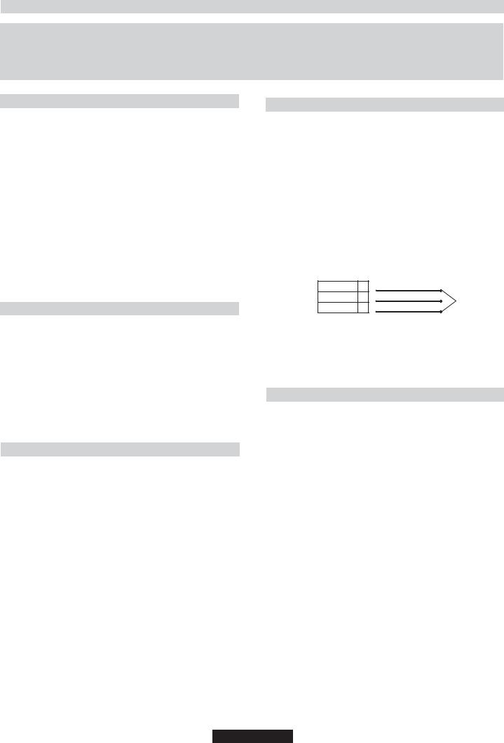
The wiring must be connected to the mains supply as follows:
CONNECT |
TO SPUR TERMINAL |
Green & Yellow Wire |
Earth Connection |
Blue Wire |
Neutral Connection |
Brown Wire |
Live Connection |
Note: We do not advocate the use of earth leakage devices with electric cooking appliances installed to spur points because of the «nuisance tripping» which may occur. You are again reminded that the appliance must be correctly earthed, the manufacturer declines any responsibility for any event occurring as a result of incorrect electrical installation.
2.1. ELECTRICAL CONNECTION
Check the data on the rating plate, located on the outside of the unit, to ensure that the supply and input voltage are suitable.
Before connection, check the earthing system.
By Law, this appliance must be earthed. If this regulation is not complied with, the Manufacturer will not be responsible for any damage caused to persons or property. If a plug is not already attached, fit a plug appropriate to the load indicated on the rating plate. The earth wire is coloured yellow/green. The plug should always be accessible.
Where the Hob is connected direct to the electricity supply, a circuit breaker must be fitted.
If the power supply cord is damaged this is to be replaced by a qualified engineer so as to prevent any potential risk.
The earth wire ( green and yellow coloured ) must be at least 10 mm longer than the live and neutral wires.
The section of the cable used must be of the correct size in relation to the absorbed power of the hob.
Please check rating plate for the power details and ensure that the power supply cord is of the type H05RR F, H05VV-F, F-H05V2V2.
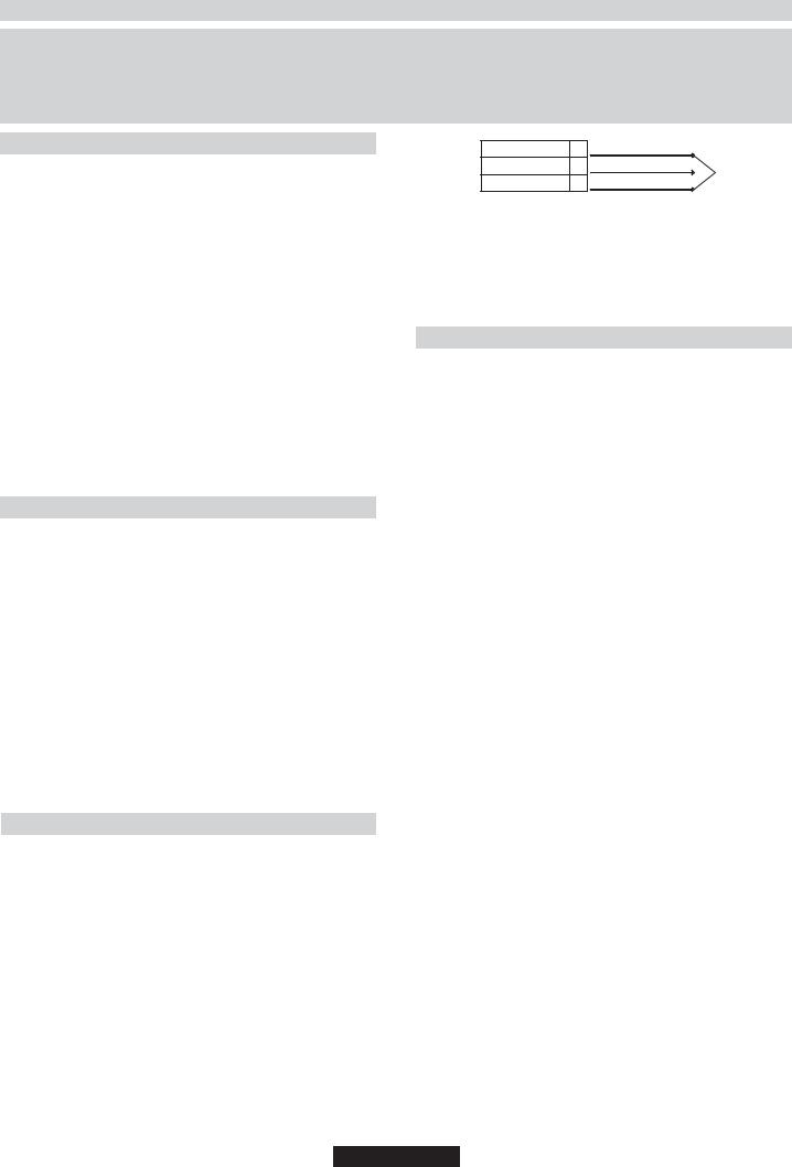
LIVE |
L |
Brown Wire |
|
Mains Supply EARTH |
|
Green/Yellow Wire |
Power Cable |
NEUTRAL N |
Blue Wire |
|
|
If an appliance is not fitted with a supply cord and a plug, or with other means for disconnection from the supply mains having a contact separation in all poles that provide full disconnection under overvoltage category III conditions, the instructions shall state that means for disconnection must be incorporated in the fixed wiring in accordance with the wiring rules.
2.2. GAS CONNECTION
These instructions are for qualified personnel, installation of equipment must be in line with the relevant national standard. (For
U.K. only: by law the gas installation\commissioning must be carried out by a "Gas Safe" installer)
All work must be carried out with the electricity supply disconnected. The rating plate on the hob shows the type of gas with which it is designed to be used. Connection to the mains gas supply or gas cylinder should be carried out after having checked that it is regulated for the type of gas with which it will be supplied. If it is not correctly regulated see the instructions in the following paragraphs to change gas setting.
For liquid gas (cylinder gas) use pressure regulators which comply with the relevant national standards.
Use only pipes,washers and sealing washers which comply with the relevant national standards.
For some models a conic link is furnished to outfit for the installation in the countries where this type of link is obligatory; in picture 8 it is pointed out how to recognize the different types of links (CY = cylindrical, CO = conic). In every case the cylindrical part of the link has to be connected to the hob.
When connecting the hob to the gas supply via use offlexible hoses please ensure that the maximum distance covered by the hose does not exceed 2 metres.
The flexible tube shall be fitted in such a way that it cannot come into contact with a moveable part of the housing unit (e.g. a drawer) and does not pass through any space where it may become crushed/ kinked or damaged in any way.
To prevent any potential damage to the hob please carry out the installation following this sequence (picture 6):
05 GB

1)As illustrated, assemble parts in sequence:
A:1/2 MaleAdaptor Cylindirical
B:1/2 Seal
C:1/2 Female GasAdaptor Conical-Cylindirical or Cylindirical-Cylindirical
2)Tighten the joints with the spanner, remembering to twist the pipes into position.
3)Attach fitting C to mains gas supply using rigid copper pipe or flexible steel pipe.
IMPORTANT: carry out a final check for leaks on the pipe connections using a soapy solution. NEVER USEAFLAME. Also, make sure that the flexible pipe cannot come into contact with a moving part of the cabinet (eg.adrawer) and that it is not situated where it could be damaged.
Warning: If gas can be smelt in the vicinity of this appliance turn off the gas supply to the appliance and call the engineer directly. Do not search for a leak with a naked flame.
2.3. ADAPTING THE HOB TO DIFFERENT TYPES OF GAS
To adapt the Hob for use with different types of gas, carry out the following instructions:
•remove the grids and burners
•insert on hexagonal spanner (7 mm) into the burner support (Figure 7)
•Unscrew the injector and replace it with one suitable for the gas to be used (see gas type table)
2.4. REGULATING THE MINIMUM FLAME
After lighting the burners, turn the control knob to the minimum setting and then remove the knob (this can easily be removed by applying gentle pressure).
Using a small «Terminal» type screwdriver the regulating screw can be adjusted as in Figure 9. Turning the screw clockwise reduces the gas flow, whilst turning it anticlockwise increases the flow – Use this adjustment to obtain a flame of approximately 3 to 4 mm in length and then replace the control knob.
When the gas supply available is LPG - the screw to set the idle flame must be turned (clockwise) to the end stop.
When you have carried out the new gas regulation, replace the old gas rating plate on your appliance with one (supplied with hob) suitable for the type of gas for which it has been regulated.
3. USE OF HOB - USER INSTRUCTIONS
This appliance must only be used for the purpose for which it is intended, domestic cooking, and any other use will be considered improper and could therefore be dangerous. The Manufacturer will not be responsible for any damage or loss resulting from improper use.
3.1. USING THE GAS BURNER
To ignite the burners, place a lighted taper close to the burner, press in and turn the control knob anti-clockwise.
If the burners have not been used for a couple of days, wait for a few seconds before lighting the burner, this will allow any air present in the pipes to escape.
For appliances fitted with electronic ignition carry out the following:
•push in and turn the knob anticlockwise to the ignition symbol.
•ignite the burner by pressing the sparker button.
For hobs fitted with automatic ignition simply push in and turn the knob to the ignition symbol.
The ignition system will continue to generate sparks as long as the control knob is being pressed.
If the burner has not ignited within 5 seconds, turn the knob to the 0 position and repeat the operation.
For models fitted with a safety tap (which cuts-off the flow of gas if the flame is accidentally extinguished) the burners are ignited and described above, but care must be taken.
Prior to switching on the gas hob ensure that the burners and burner caps are correctly placed within their position.
GENERALADVISE
For best results, use cooking vessels with a flat surface. The size of the surface should match the gas burner side as follows. TableA.
Burner Type |
Ø pan/pot |
Power |
G20/20 mbar |
G30/28-30 mbar |
||
(cm) |
(kW) |
(methane) |
(LPG) |
|||
|
|
|||||
AUX Auxiliary |
12 - 18 |
1,00 |
95 l/h |
73 g/h |
||
SR |
Semi Rapid |
18 - 24 |
1,75 |
167 l/h |
127 g/h |
|
R |
Rapid |
24 - 26 |
2,50 |
238 l/h |
182 g/h |
|
Table A
For smaller containers the gas burner should be regulated so that the flame does not overlap the base of the pan. Vessels with a concave or convex base should not be used.
WARNING: If a flame is accidentally extinguished, turn the knob to the off position and do not attempt to re-ignite if for at least 1 minute.
If over the years the gas taps become stiff to turn it is necessary to lubricate them.
Such operation must be carried out only by qualified Service Engineers.
Suitability of Cooking Pans (Figure 10)
Keep in mind that larger pans have larger heating surfaces.
This will help them to cook the food faster than pans with smaller heating surfaces.
Always use pan sizes proportionate to the amount of the food to be cooked. In order to prevent splashing, do not use very small pans, especially for foods with excess liquid. If you use excessively large pans for quick cooked foods, sausages and liquids will stick and residues will remain attached to the pan after being emptied.
Closed pans and baking trays or moulds are suggested for cooking sweets. Splashed sugar and juices from an open pan may stick to the cooker surface and will be difficult to remove.
This is especially important for pans used for roasting or pressurized cooking at high temperature.
Do not leave burners unattended without a pan or with an empty pan on top.
Check the suitability of cooking pans with respect to the following criteria;
They should be heavy.
They should completely cover the burner surface; they may be a little bigger but no smaller. (See Table)
4. MAINTENANCE AND CLEANING
Before cleaning the hob, ensure the appliance has cooled down. Remove the plug from the socket or (if connected directly) switch off the electricity supply.
Never use abrasives, corrosive detergents, bleaching agents or acids. Avoid any acid or alkaline substances (lemon, juice, vinegar etc.) on the enamelled, varnished or stainless steel sections.
When cleaning the enamelled, varnished or chrome sections, use warm soapy water or a non caustic detergent. For stainless steel use an appropriate cleaning solution.
The burners can be cleaned with soapy water. To restore their original shine, use a household stainless steel cleaner. After cleaning, dry the burners and replace.
It is important the Burners are replaced correctly.
5. AFTERCARE
Before calling out a Service Engineer please check the following:
•that the plug is correctly inserted and fused;
•that the gas supply is not faulty.
If the fault cannot be detected:
Switch off the appliance and call the After Service Centre. DO NOT TAMPER WITH THEAPPLIANCE.
06 GB

6. PROTECTION OF THE ENVIRONMENT
This appliance is marked according to the European directive 2012/19/EU on Waste Electrical and Electronic Equipment (WEEE). WEEE contains both polluting substances (which can cause negative consequences for the environment) and basic components (which can be re-used). It is important to
have WEEE subjected to specific treatments, in order to remove and dispose properly all pollutants, and
recover and recycle all materials.
Individuals can play an important role in ensuring that WEEE does not become an environmental issue; it is essential to follow some basic rules:
•WEEE shall not be treated as household waste.
•WEEE shall be handed over to the relevant collection points managed by the municipality or by registered companies. In many countries, for large WEEE, home collection could be present.
•When you buy a new appliance, the old one may be returned to the retailer who has to collect it free of charge on a one-to-one basis, as long as the equipment is of equivalent type and has the same functions as the supplied equipment.
Declaration of compliance: This equipment, in the parts intended to come into contact with food, complies with the regulations laid down in EEC directives 89/109.
Appliance complies with European Directives 2006/95/EC, 2004/108/EC and 2009/142/EC and subsequent
amendments.
The Manufacturer will not be responsible for any inaccuracy resulting from printing or transcript errors contained in this brochure. We reserve the right to carry out modifications to products as required, including the interests of consumption, without prejiudice to the characteristics relating to safety or function.
|
|
|
|
Table 1 |
|
|
|
|
|
|
BUILT IN HOBS |
|
||
|
|
1 |
|
|
Burner |
|
4 gas |
|
|
|
|
R /2SR / AUX |
|
|
|
|
|
|
|
Type / reference |
|
PVL6SL |
|
|
Flame failure device |
YES |
|
|
|
Auxiliary burner |
( AUX Ø 50 mm) |
1 |
|
|
|
|
|
|
|
Semirapid burner |
( SR Ø 75 mm) |
2 |
|
|
Rapid burner |
( R Ø 100 mm) |
1 |
|
|
Installed Gas Type / Power: |
|
|
|
|
Gas Power |
|
7.0 kW |
|
|
G 20/20 mbar (methane) |
666 l/h |
|
|
|
G 30/28-30 mbar (LPG) |
509 g/h |
|
|
|
|
|
|
|
|
Installation Class |
|
3 |
|
|
|
|
|
|
|
Voltage / Frequency V / Hz |
220-240 V / 50-60 Hz |
|
|
|
|
|
|
|
|
Electrical input power |
25 W |
|
|
|
|
|
|
|
|
Electric ignition |
|
YES |
|
|
Product dimension |
|
585 x 510 |
|
|
This appliance has been designed for non-professional, i.e. domestic, use.
07 GB

INSTRUKCJE BEZPIECZEŃSTWA
UWAGA: Podczas pracy urządzenie oraz jego elementy są gorące. Należy zachowac ostrożność i nie dotykać gorących części.
•Dzieci w wieku do 8 lat nie mogą zbliżać się do urządzenia chyba że pozostaja one pod ciągłym nadzorem.
•Dzieci w wieku powyżej 8 lat oraz ososby z ograniczeniami ruchowymi, umysłowymi, czuciowymi lub nie posiadające odpowiedniej wiedzy lub doświadczenia mogą obsługiwać urządzenie jedynie pod nadzorem lub po przeszkoleniu odnośnie bezpiecznego użytkowania urządzenia i związanych z tym zagrożeń.
•Dzieci nie mogą bawić się urządzeniem.
•Dzieci bez nadzoru nie mogą obsługiwac ani czyścić urządzenia.
UWAGA: gotowanie na płycie z użyciem oleju lub tłuszczu bez nadzoru może być niebezpieczne i spowodować pożar.
•NIGDY nie gasić ognia wodą, należy wyłączyc urządzenie i przykryć płomień np. pokrywką lub kocem ognioodpornym.
UWAGA: niebezpieczeństwo pożaru. Nie wolno przchowywać przedmiotów na powierzchniach grzejnych.
UWAGA: dostępne części mogą być gorące podczas użytkowania. Dzieci nie mogą zbliżać się do urządzenia.
•Nie stosować do czyszczenia urządzeń parowych.
•Usunąć wylany płyn z pokrywy przed otwarciem.
•Poczekać aż powierzchnia płyty ostygnie przed zamknięciem pokrywy.
•Urządzenie nie jest przeznaczone do sterowania zewnętrznym minutnikiem lub oddzielnym układem zdalnego sterowania.
•Wyłącznik musi być podłączony do okablowania zgodnie z obowiązujacymi przepisami.
instrukcja musi określać jaki rodzaj przewodu może być zastosowany, z uwzglednieniem temperatury tylnej ścianki urządzenia.
•Jeżeli przewód zasilający jest uszkodzony musi być wymieniony przez producenta lub autoryzowany serwis tak aby uniknąc wszelkiego ryzyka.
UWAGA: w celu uniknięcia zagrożeń związanych z przypadkowym zadziałaniem zabezpieczeń termicznych urządzenie nie może być zasilane z sieci sterowanej niezależnie lub z obwodów które są regularnie włączane i wyłączane.
•Urządzenie musi być zainstalowane zgodnie z obowiązującymi przepisami i w miejscu dobrze wentylowanym. Proszę zapoznać się z instrukcją przed przystapieniem do instalacji.
Te instrukcje są ważne jedynie dla krajów których symbol pojawia się na urządzeniu. Jeżeli symbol kraju jest nieobecny należy odnieść się do insterukcji technicznej określającej zmiany urządzenia wprowadzone dla danego kraju.
•Przed instalacją należy upewnić się czy lokalne warunki (rodzaj i ciśnienie gazu) są zgodne z ustawieniami urządzenia;
•Ustawienia urządzenia są podane na tabliczce znamionowej;
•Urządzenie nie jest podłączone do układu odprowadzania gazów spalinowych. Musi być podłączone do takiego układu zgodnie z przepisami ze szczególnym uwzględnieniem wymagań odnośnie wentylacji
.
08 PL
1. INSTRUKCJE DLA INSTALATORA
INSTALACJA URZĄDZENIA DOMOWEGO MOŻE BYĆ SKOMPLIKOWANĄ OPERACJĄ, KTÓRA JEŻELI NIE BĘDZIE WYKONANA PRAWIDŁOWO, MOŻE POWAŻNIE ZAGROZIĆ BEZPIECZEŃSTWU UŻYTKOWNIKA. DLATEGO TEŻ, ZADANIE TO POWINNO BYĆ WYKONANE PRZEZ OSOBĘ O ODPOWIEDNICH KWALIFIKACJACH ORAZ ZGODNIE Z OBOWIĄZUJĄCYMI PRZEPISAMI. W PRZYPADKU ZIGNOROWANIA NINIEJSZEGO ZALECENIA I WYKONANIA INSTALACJI PRZEZ OSOBĘ BEZ ODPOWIEDNICH KWALIFIKACJI, PRODUCENT NIE PONOSI ŻADNEJ ODPOWIEDZIALNOŚCI ZA JAKIEKOLWIEK USTERKI TECHNICZNE, BEZ WZGLĘDU NATO, CZY SPOWODUJĄ ONE SZKODY W MIENIU, CZY TEŻ USZKODZENIACIAŁAU LUDZI.
1.1. ZABUDOWA
Płytę można zamontować w dowolnym blacie kuchennym, który jest odporny na działanie temperatury do 100C oraz posiada grubość 25-45 mm. Wymiary otworu, który należy wyciąć w blacie kuchennym, podane są na Rysunku 2.
Jeżeli kuchenka jest montowana obok szafki kuchennej, odległość pomiędzy płytą i szafką musi być co najmniej 15 cm (patrz Rysunek 4); natomiast odległość pomiędzy płytą i ścianą kuchni musi być co najmniej 5,5 cm.
Odległość pomiędzy płytą i szafką lub jakimkolwiek urządzeniem zamontowanym nad kuchenką (np. okapem) musi być nie mniejsza niż 70 cm (Rysunek 4).
Jeżeli pod zabudowaną płytą znajduje się dostępna przestrzeń, konieczne jest zamontowanie przegrody z materiału izolacyjnego (np. drewna) (Rysunek 3).
Uwaga - Na Rysunku 1 pokazano sposób przyklejenia uszczelki.
Płytę należy zamocować przy użyciu uchwytów znajdujących się w jej wyposażeniu, korzystając z otworów wykonanych w podstawie płyty.
W przypadku montowania płyty o szerokości 60 cm nad piekarnikiem, który nie jest wyposażony w obieg chłodzący, zaleca się utworzenie otworów w zabudowie w celu zapewnienia prawidłowego przepływu powietrza.
Wielkość tych otworów powinna wynosić co najmniej 300 cm2 i należy je rozmieścić w sposób pokazany na Rysunku 5.
1.2. ODPOWIEDNIE POMIESZCZENIE
W przestrzeni, w której zainstalowana jest kuchenka gazowa powstają duże ilości ciepła i pary. Dlatego też, konieczne jest zapewnienie dobrej wentylacji poprzez utrzymywanie naturalnego obiegu powietrza lub poprzez zamontowanie okapu kuchennego z wyciągiem. W przypadku długiego i intensywnego użytkowania kuchenki, konieczne może być zastosowanie dodatkowej wentylacji, na przykład poprzez otwarcie okna lub zwiększenie obrotów wentylatora.
•Przed instalacją należy upewnić się czy lokalne warunki (rodzaj i ciśnienie gazu) są zgodne z ustawieniami urządzenia;
•Ustawienia urządzenia są podane na tabliczce znamionowej; •Urządzenie nie jest podłączone do układu odprowadzania gazów spalinowych. Musi być podłączone do takiego układu zgodnie z przepisami ze szczególnym uwzględnieniem wymagań odnośnie wentylacji .
Przy braku możliwości zamontowania okapu, w ścianie zewnętrznej lub w oknie należy zainstalować wentylator elektryczny pod warunkiem, że pomieszczenie posiada otwory odpowietrzające.
Wentylator elektryczny powinien zapewniać pełną wymianę powietrza w kuchni w tempie 3-5 razy na godzinę. Instalator powinien przestrzegać obowiązujących w danym kraju przepisów.
2.1. PODŁĄCZENIE DO SIECI ELEKTRYCZNEJ
Zacisk sieci |
FAZOWY |
L Przewód brązowy |
Kabel |
|
UZIEMIENIE |
Przewód żółtozielony |
|||
zasilającej |
zasilający |
|||
|
NEUTRALNY |
N Przewód niebieski |
||
|
|
Jeśli urządzenie nie posiada kabla i wtyczki lub innego rozwiązania umożlwiającego odłączenie od odpowiednio zabezpieczonej sieci elektrycznej pozwalającej na pełne odłączenie przy wystąpieniu nadnapięcia spełniającego warunki kategorii III,instrukcja stwierdza, że sposoby odłączenia muszą być wbudowane w instalację elektryczną, zgodnie z zasadami okablowania.
2.2. PODŁĄCZENIE DO GAZU
Poniższe instrukcje przeznaczone są dla wykwalifikowanego personelu, instalacja urządzenia musi być zgodna z obowiązującymi normami krajowymi. (Wyłącznie dla Wielkiej Brytanii: zgodnie z przepisami prawa, instalacja gazowa i jej odbiór muszą być przeprowadzone przez instalatora zarejestrowanego w CORGI)
Wszystkie prace muszą być wykonane przy odłączonym zasilaniu elektrycznym.
Na tabliczce znamionowej urządzenia wskazany jest rodzaj gazu do którego zostało ono przystosowane. Podłączenie do sieci gazowej lub do butli z gazem płynnym należy przeprowadzić po uprzednim upewnieniu się, że urządzenie jest wyregulowane dla danego rodzaju gazu, który ma być podłączony. Jeżeli urządzenie nie jest prawidłowo wyregulowane, patrz instrukcje w kolejnym punkcie na temat zmiany ustawień gazowych.
W przypadku butli z gazem płynnym (butli gazowej) należy zastosować regulator ciśnienia zgodny z obowiązującymi normami krajowymi. Należy stosować wyłącznie rury, podkładki i uszczelki, które są zgodne z obowiązującymi normami krajowymi.
W niektórych modelach, na wyposażeniu urządzenia znajduje się łącznik stożkowy, przeznaczony do zamontowania na terenie krajów, w których ten typ łącznika jest obligatoryjny; na rysunku 8 pokazano w jaki sposób rozróżnić poszczególne typy łącznika (CY = cylindryczny, CO = stożkowy). W każdym przypadku, cylindryczna część łącznika musi być podłączona do płyty gazowej.
W przypadku podłączania płyty do gazu przy użyciu przewodów elastycznych, należy zapewnić, aby maksymalna odległość łączenia tym przewodem nie przekroczyła 2 metrów.
Elastyczny przewód przyłączeniowy powinien być umieszczony w taki sposób, żeby nie dotykał ruchomych części mebli lub innych przedmiotów (np. szuflady) i nie przechodził przez żadne miejsca gdzie może zostać zgnieciony/złamany lub uszkodzony w inny sposób.
Aby zapobiec ewentualnemu uszkodzeniu płyty, należy zachować następującą kolejność podczas instalacji (rysunek 6):
Upewnić się, że napięcie w sieci odpowiada napięciu podanemu na tabliczce znamionowej znajdującej się na obudowie urządzenia.
Przed podłączeniem, sprawdzić obwód uziemienia.
Zgodnie z przepisami prawa, niniejsze urządzenie musi być uziemione. W razie nie przestrzegania tego wymagania, producent nie poniesie żadnej odpowiedzialności za jakiekolwiek szkody w stosunku do osób lub mienia. Jeżeli kabel zasilający nie posiada wtyczki, należy zamontować wtyczkę dopasowaną do obciążenia wskazanego na tabliczce znamionowej urządzenia. Przewód uziemienia jest w kolorze żółtozielonym. Wtyczka powinna być zawsze dostępna.
W przypadku gdy płyta podłączona jest bezpośrednio do sieci elektrycznej, konieczne jest zainstalowanie wyłącznika automatycznego. W razie uszkodzenia kabla zasilającego, musi on być wymieniony przez wykwalifikowanego elektryka w celu wyeliminowania potencjalnych zagrożeń.
Przewód uziemienia (w kolorze żółtozielonym) musi być co najmniej 10 mm dłuższy niż przewód fazowy i neutralny.
Przekrój poprzeczny kabla zasilającego musi być o wielkości dostosowanej do mocy pobieranej przez płytę.
Sprawdzić na tabliczce znamionowej dane dotyczące podłączenia do sieci elektrycznej oraz upewnić się, że kabel zasilający jest typu 3x0.75 mm² H05RR-F.
1)Jak pokazano na rysunku, kolejno zamontować:
A: Łącznik cylindryczny męski 1/2" B: Uszczelka 1/2"
C: Łącznik gazowy damski stożek-cylinder lub cylinder -cylinder 1/2"
2)Zacisnąć połączenie przy użyciu kluczy, pamiętając o ułożeniu przewodów rurowych w odpowiednim położeniu.
3)Podłączyć łącznik C do domowej instalacji gazowej przy użyciu sztywnego przewodu miedzianego lub stalowego przewodu elastycznego.
UWAGA: sprawdzić szczelność połączeń przewodów rurowych przy użyciu roztworu wody z mydłem. Nigdy nie należy do tego celu używać płomienia. Należy również upewnić się, że przewód elastyczny nie wejdzie w kontakt z ruchomą częścią szafki (np. szufladą), oraz że jest on ułożony w sposób wykluczający jego uszkodzenie.
Ostrzeżenie: Jeżeli w pobliżu urządzenie wyczuwalny jest gaz, należy natychmiast odciąć dopływ gazu do urządzenia i wezwać instalatora. Nie próbować wykrywania nieszczelności przy pomocy otwartego płomienia.
09 PL
 Loading...