


EN HOBS 70 cm
USER INSTRUCTIONS
TECHNICAL CHARACTERISTICS
Cooking hobs 70x50 |
|
|
|
|
|
|
|
|
|
|
|
|
|
|
|
Burners |
|
5 gas |
5 gas |
5 gas |
5 gas |
5 gas |
5 gas |
|
|
– |
– |
– |
– |
– |
– |
Reference type |
|
P751 |
P751 |
P751 |
P752 |
P752 |
P752 |
Supply Voltage |
(V/Hz) |
230/50 |
230/50 |
230/50 |
230/50 |
230/50 |
230/50 |
Installed electric power |
(W) |
– |
– |
– |
– |
– |
– |
Medium burner |
|
1 |
1 |
1 |
1 |
1 |
1 |
Large burner |
|
2 |
2 |
2 |
2 |
2 |
2 |
Small burner |
|
1 |
1 |
1 |
1 |
1 |
1 |
Double ring burner |
|
1 |
– |
– |
1 |
– |
– |
Maxi burner |
|
– |
1 |
– |
– |
1 |
– |
Fish burner |
|
– |
– |
1 |
– |
– |
1 |
Power of gas installed: |
|
|
|
|
|
|
|
- Natural gas 1,0 kPa (MJ/H)** |
|
40,5 |
40,5 |
40,5 |
40,5 |
40,5 |
40,5 |
- LPG gas 2,75 kPa (MJ/H) |
|
37,4 |
37,4 |
37,4 |
37,4 |
37,4 |
37,4 |
Electric ignition* |
|
yes |
yes |
yes |
yes |
yes |
yes |
Gas safety device |
|
– |
– |
– |
yes |
yes |
yes |
Product size |
mm. |
695x510 |
695x510 |
695x510 |
695x510 |
695x510 |
695x510 |
Degree protection |
|
– |
– |
– |
– |
– |
– |
Class |
|
3 |
3 |
3 |
3 |
3 |
3 |
|
Fig. 1 |
* Some models only |
** Manufacturer setting |
1
INSTALLATION
The Purchaser is responsible for the installation of the hob. The Manufacturer does not accept any responsibility for any damage or loss resulting from incorrect installation, and as such this will not covered by the Manufacturer’s Guarantee.
The hob may be installed in any worktop which is heat resistant to a temperature of 100° C, and has a thickness of 25 - 40 mm. The dimensions of the insert to be cut out of the worktop are in shown in Fig. 1.
|
If the Hob is fitted next to a cabinet on either side, |
|
150 mm |
||
min. |
the distance between the Hob and the cabinet |
|
|
must be at least 150 mm (see Fig. 2); while the |
|
|
distance between the hob and the rear wall must |
|
30 mm |
be at least 55 mm. |
|
If below the hob there is an accessible space, |
||
|
||
|
there must be a partition panel in insulating mate- |
|
10 mm |
rial (wood or similar) providing a space of at least |
|
10 mm below the Hob (see Fig. 2). |
||
Partition panel |
||
The Hob unit is fitted by attaching the Fixing |
||
Fig. 2 |
||
|
Clamps supplied, using the holes at the base of |
|
|
||
|
the unit. |
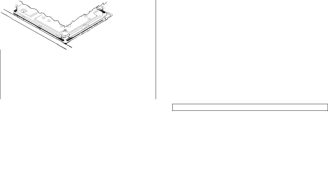
VERY IMPORTANT - APPLYING THE SEALANT
Important - The diagram below shows how the sealant should be applied.
This appliance has been designed for non-professional, i.e. domestic, use.
Appropriate checks and tests have ensured that, even in the most extreme conditions, the temperatures reached are within acceptable limits. The Hob is thermally insulated (in line with Regulation EN) and may be installed: next to panels higher than the worktop, for type «Y», or next to panels not higher than the worktop for type «X». See technical characteristics table «Degree of protection».
2

Instructions for the installer
Suitable location
A gas-powered cooking appliance produces heat and himidity in the area in which it is installed. For this reason you should ensure good ventilation either by keeping all natural air passages open or by installing an extractor hood with an ehaust flue (Fig. 3-4). Intensive and prolonged use of the appliance may require extra ventilation, such the opening of a window or an increase in speed of the electric fan, if you have one.
If your appliance is not fitted with a thermocouple (safety device) the ventilation hole shown in Fig. 3 should be at least 200 cm2.
Fig. 3
If a hood cannot be installed, an electric fan should be fitted to an outside wall or window as long there are air vents in the area.
The electric fan should be able to carry out a complete change of air in the kitchen 3-5 times every hour.
The installer should follow the relavant national standards.
Fig. 4
Electrical connection
Check the data on the rating plate, located on the outside of the unit, to ensure that the supply and input voltage are suitable.
Before connection, check the earthing system.
By Law, this appliance must be earthed. If this regulation is not complied with, the Manufacturer will not be responsible for any damage caused to persons or property. If a plug is not already attached, fit a plug appropriate to the load indicated on the rating plate. The earth wire is coloured yellow/green.
Where the Hob is connected direct to the electricity supply, a circuit breaker must be fitted with at least a 3 mm contact spacing when in the open position.
It if is necessary to replace the connecting cable, the earth wire (yellow/green) must, by law, be approximately 10 mm longer than the live and neutral wires. Rubber insulated cable type H05RR-F must be used.
The cables should be 1,5 mm2 section for products with electrically heated elements,
3
and 0,75 mm2 for others products. Also, the maximum external diameter of the cable should not be greater than 7 mm.
MAINS |
LIVE |
|
L |
|
|
|
|
BROWN WIRE |
||||
EARTH |
|
|
|
|
|
|
|
|
GREEN/YELLOW WIRE POWER |
|||
SUPPLY |
|
|
|
|
|
|
|
|
||||
|
|
|
|
|
|
|
|
|||||
|
|
|
|
|
|
|
|
|
|
|
CABLE |
|
NEUTRAL |
|
N |
|
|
|
|
|
|
||||
|
|
|
|
|
|
BLUE WIRE |
||||||
|
|
|
|
|
|
|
|
|
|
|
|
|
Declaration of compliance. The parts of this equipment which are designed to come into contact with foodstuffs, comply with EEC directive 89/109.
Appliance complying with European directives 89/336/EEC, 90/396/EEC, 73/23/EEC and subsequent modifications.
Gas connection
The rating plate on the hob shows the type of gas with which it is designed to be used. It is possible to use other types of gas after carrying out some simple modifications. a) Connection to the gas supply
—connection to the mains gas supply or gas cylinder should be carried out according to the relevant national standards, after having checked that it is regulated for the type of gas with which it will be supplied. If it is not correctly regulated follow the instructions in the paragraph entitlet «Adaption for different types of gas». For liquid gas (cylinder gas) use pressure regulators which comply with the relevant national standards.
N.B.: for safe operation, economic use of energy and to ensure greater durability of the appliance, make sure that the supply pressure conforms with the values shown in the table on page 6 .
—Connection to a rigid pipe (see instruction on page 10)
Connection to the gas supply should be done without putting any kind of stress on the appliance.
—Connection to a flexible steel pipe (see instructions on page 10)
The junction of the gas pipe with the appliance is a 1/2” gas tapered thread connection. Use only pipes, washers and sealing washers which comply with the relevant national standards.
The fitting of these pipes should be done to that their maximum length, when fully extended, should not exceed 2000 mm.
N.B.: carry out a final check for leaks on the pipework using a soapy solution. Never use a flame. Also, make sure that the flexible pipe cannot come into contact with a movlng part of the cabinet (eg, a drawer) and that it is not situated where it could be damaged.
4
 Loading...