


Downloaded from
www . vandenborre . be
|
Downloaded |
|
from |
|
www |
|
. |
|
vandenborre |
|
. |
|
be |
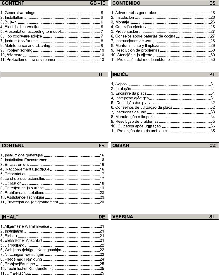
SOMMARIO |
|
1. AVVERTENZE GENERALI............................................ |
11 |
2. INSTALLAZIONE ......................................................... |
11 |
3. INSERIMENTO MOBILE............................................... |
11 |
4. COLLEGAMENTO ELETTRICO ................................... |
11 |
5. PRESENTAZIONE ...................................................... |
12 |
6. CONSIGLI D'UTILIZZO................................................. |
12 |
7. UTILIZZO DEL PIANO .................................................. |
13 |
8. MANUTENZIONE ......................................................... |
14 |
9. PROBLEMI E SOLUZIONI............................................ |
15 |
10. ASSISTENZA POST-VENDITA ................................... |
15 |
11. RISPETTO DELL'AMBIENTE ..................................... |
15 |
1. |
Všeobecná upozornění ................................................. |
36 |
2. |
Instalace ........................................................................ |
36 |
3. |
Vestavění ...................................................................... |
36 |
4. |
Připojení k elektrické síti................................................ |
36 |
5. |
Popis spotřebiče............................................................ |
37 |
6. |
Doporučení k nádobí .................................................... |
37 |
7. |
Použití............................................................................ |
38 |
8. |
Čištění a údržba ............................................................ |
39 |
9. |
Problémy a řešení ......................................................... |
40 |
10. Kontrola ....................................................................... |
40 |
|
11. Informace pro uživatele k likvidaci elektrických |
|
|
a elektronických zařízení (domácnosti) ............................ |
40 |
|
1. |
Splošni varnostni napotki ............................................. |
41 |
2. |
Namestitev in priključitev ............................................... |
41 |
3. |
Vgradnja ........................................................................ |
41 |
4. |
Priključitev na električno omrežje................................... |
41 |
5. |
Opis kuhalne plošče ...................................................... |
42 |
6. |
Ustrezna posoda ........................................................... |
42 |
7. |
Uporaba ........................................................................ |
43 |
8. |
Vzdrževanje in čiščenje.................................................. |
44 |
9. |
Odpravljanje nepravilnosti v delovanju .......................... |
45 |
10. Servisiranje .................................................................. |
45 |
|
11. Varstvo okolja .............................................................. |
45 |
|

|
|
RU |
1. |
МЕРЫ ПРЕДОСТОРОЖНОСТИ ................................. |
46 |
2. |
УСТАНОВКА ................................................................ |
46 |
3. |
ВСТРАИВАЕМАЯ БЫТОВАЯ ТЕХНИКА .................... |
46 |
4. |
ПОДКЛЮЧЕНИЕ К ЭЛЕКТРОСЕТИ............................ |
46 |
5. |
ОПИСАНИЕ .................................................................. |
47 |
6. |
СОВЕТЫ ОТНОСИТЕЛЬНО ВЫБОРА КУХОННОЙ |
|
ПОСУДЫ ДЛЯ ИСПОЛЬЗОВАНИЯ С ВАРОЧНОЙ |
|
|
ПОВЕРХНОСТЬЮ............................................................ |
47 |
|
7.CTEЛОКEPAMИЧECКAЯ BAPOЧHAЯ ПOBЕРXHOCTЫ C |
|
|
CEHCOPЫM УПPABЛEH ИEM ....................................... |
48 |
|
8. |
ЧИCTKA И OБCЛУЖИBAHИE..................................... |
49 |
9. |
ПOCЛEПPOДAЖHOE OБCЛУЖИBAHИE................... |
49 |
10. PEШEHИE ПPOБЛEM................................................ |
50 |
|
Downloaded from

 www
www  .
. 
 vandenborre
  . be
. be

 Ś
Ś
 PODŁĄCZENIE ELEKTRYCZNE
 WSKAZÓWKI ODNOŚNIE NACZYŃ
 UŻYTKOWANIE
 UŻYTKOWANIE
 ROZWIĄZYWANIE PROBLEMÓW
 Ś
Ś

|
Downloaded |
||
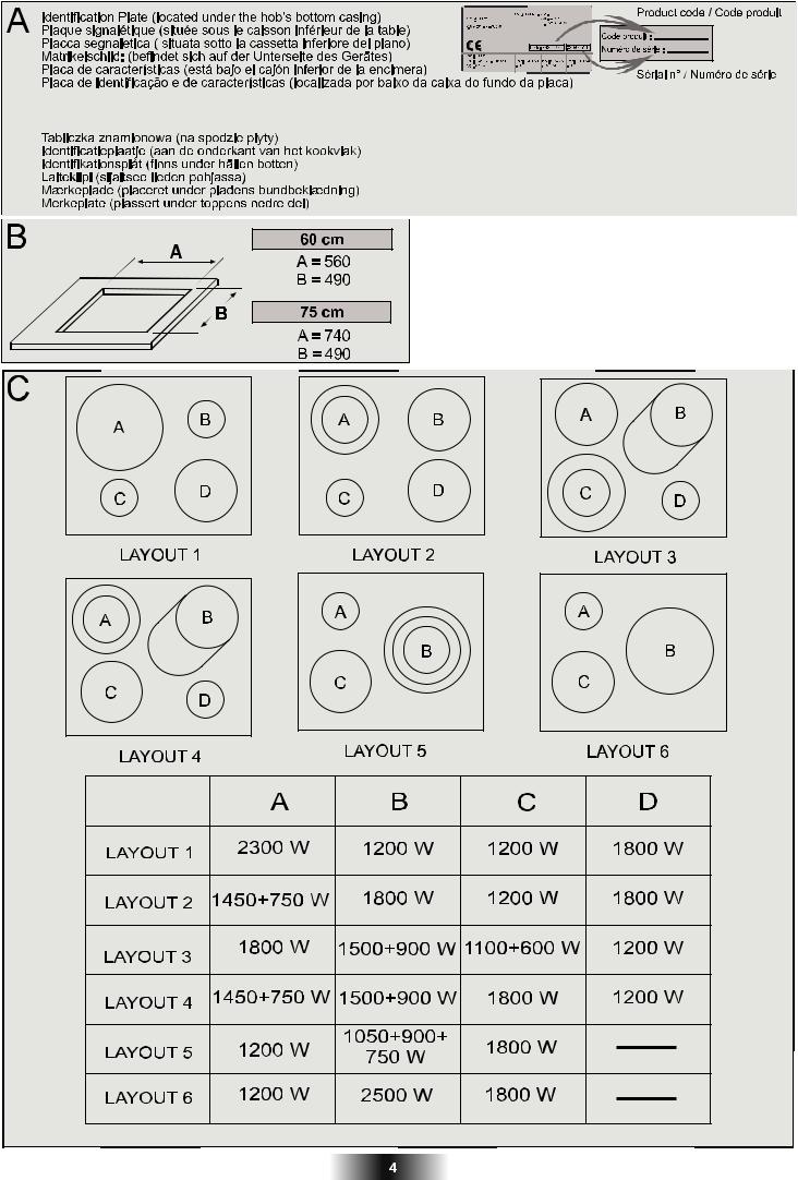
Výrobní štítek (umístěný pod spodním krytem desky) |
|
from |
|
Tablica s podatki (na spodnji strani ohišja) |
|
www |
|
Паспортная табличка (расположена в нижней части корпуса варочной поверхности) |
|||
|
|||
|
|
. |
|
|
|
vandenborre |
|
|
|
. |
|
|
|
be |
|
Těsnění |
Tesnilo |
Πрокладка |
Downloaded |
from |
www |
. |
vandenborre |
. |
be |
CZZakázané instalovat varnou desku nad troubu bez ventilátoru. SL-Kuhalne plošče ni dovoljeno vgraditi nad pečico brez ventilatorja za hlajenje
RU-Запрещается устанавливать варочную поверхность над невентилируемой духовкой
Podle modelu - Odvisno od modela
 - Časovač - PROGRAMSKA URA – ŠTEVEC MINUT
Vnější varná zóna - Razširitev kuhališča
- Led vnější varné zóny - Kontrolna lučka razširjenega kuhališča
Kontrolka programování varné zóny - Kontrolna lučka programiranega kuhališča
 - Kontrolní LED - Kontrolna lučka delovanja

READ THE INSTRUCTIONS BOOKLET CAREFULLY TO MAKE THE MOST OF YOUR HOB.Downloaded
We recommend you keep the instructions for installation and use for later reference, and before installing the hob, note its serial number in case you need to get help from the after sales service.
• It is strongly recommended to keep children away from the cooking zones while they are in operation or whenfromthey are switched off, so long as the residual heat indicator is on, in order to prevent the risks of serious burns.
• When cooking with fats or oils, take care always to watch the cooking process as heated fats and oils can catch fire rapidly. |
|
• Aluminium foil and plastic pans must not be placed on heating zones. |
www |
|
. |
• After every use, some cleaning of the hob is necessary to prevent the build up of dirt and grease. If left, this is recooked when the |
|
hob is used and burns giving off smoke and unpleasant smells, not to mention the risks of fire propagation. |
vandenborre |
• It is advisable not to stare directly at the halogen elements. |
|
• Do not touch the heat zones during operation or for a while after use. |
|
• Never cook food directly on the glass ceramic hob. Always use the appropriate cookware. |
|
• Always place the pan in the centre of the unit that you are cooking on. |
. |
• Do not use the surface as a cutting board. |
|
• Do not slide cookware across the hob. |
be |
• Do not store heavy items above the hob. If they drop onto the hob, they may cause damage.
• Do not use the hob as a working surface.
• Do not use the hob for storage of any items.
• In the unlikely event of a surface crack appearing, do not use the hob.
Immediately disconnect the hob from the electrical power supply and call the After Sales Service
• Never use a steam or high pressure spray to clean the appliance.
• This appliance is not intended for use by persons (including children) with reduced physical, sensory or mental capabilities, or lack of experience and knowledge, unless they have been given supervision or instruction concerning use of the appliance by a person responsible for their safety.
• Children should be supervised to ensure that they do not play with the appliance.
We are constantly striving to improve product quality and as such may modify appliances to incorporate the latest technical improvements.
Appliance complies with European Directives 73/23/EEC and 89/336/EEC, replaced by 2006/95/EC and 2004/108/EC, and subsequent amendments.
2. INSTALLATION
Installing a domestic appliance can be a complicated operation which if not carried out correctly, can seriously affect consumer safety. It is for this reason that the task should be undertaken by a professionally qualified person who will carry it out in accordance with the technical regulations in force. In the event that this advice is ignored and the installation is carried out by an unqualified person, the manufacturer declines all responsibility for any technical failure of the product whether or not it results in damage to goods or injury to individuals.
3. BUILT-IN
The furniture in which your hob will be installed and all adjacent furniture, should be made from materials that can withstand high temperatures. In addition, all decorative laminates should be fixed with heat-resistant glue.
Installation (Fig. B / D):
• A watertight seal is supplied with the hob.
Before fitting:
-turn the hob upside down, with the glass surface facing downwards.
Make sure the glass is protected.
-fit the seal round the hob.
-make sure that it is correctly fitted to avoid any leakage into the supporting cabinet.
•Leave a gap of at least 5 cm between the appliance and the vertical sides of the adjacent furniture.
•If, when installing the hob, the lower hob face is adjacent to an area normally accessible when handling or cleaning, fit a partition 1 cm below the base of the hob to avoid any risk of scorching or damage.
4. ELECTRICAL CONNECTION
"The installation must conform to the standard directives."
The manufacturer declines all responsibility for any damage that may be caused by unsuitable or unreasonable use.
Warning:
we cannot be held responsible for any incident or its consequences that may arise during the use of an appliance not linked to the earth, or linked to an earth whose continuity is defective.
•Always check before any electrical operation, the supply tension shown on the electricity meter, the adjustment of the circuitbreaker, the continuity of the connection to earth to the installation and that the fuse is suitable.
•The electrical connection to the installation should be made via a socket with a plug with earth, or via an omnipole cut-out switch.
If the appliance has a socket outlet, it must be installed so that the socket outlet is accessible.
•The yellow/green wire of the power supply cable must be connected to the earth of both power supply and appliance terminals.
•Any queries regarding the power supply cord should be referred to After Sales Service or a qualified technician.
6 GB-IE
ATTENTION:
should it be necessary to replace the supply cord, connect the wire in accordance with the following colours/codes:
BLUE |
- NEUTRAL (N) |
||||
BROWN |
- LIVE (L) |
||||
YELLOW-GREEN |
- EARTH ( |
|
|
|
) |
|
|||||
|
|
|
|||
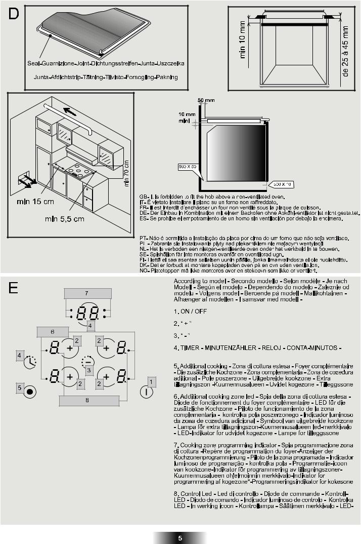
The hob is fitted with a power supply cord which allows it to be connected only to a power supply of 220-240 V between phases or between phase and neutral.
• Connect to a socket, to choose the correct fuse, you must refer on the table.
It is however possible to connect the hob to :
. Three phase |
220-240 |
V3~ |
. Three phase |
380-415 |
V2N~ |
To proceed to the new connection, you must adhere the following instructions.
•Before making the connection, make sure that the installation is protected by a suitable fuse, see table, and that it is fitted with wires of a large enough section to supply the appliance normally.
•Turn over the hob, glass side against the work top, taking care to protect the glass.
•Open the cover in the following sequence:
1 |
2 |
3 |
•unscrew the cable clamp "1",
•find the two tabs located on the sides,
•put the blade of a flat screw-driver in front of each tab "2" e "3", push in and press,
•remove the cover.
To release the power supplying cord.
• remove the screws retaining the terminal block which contains the shunt bars and the conductors of the supply cord,
•Pull out the supply cord.
•Operations to be carried out to make a new connection :
-Choose the power supply cable in accordance with the recommendations in the table.
-Pass the power supply cable into the clamp.
SHUNT |
- Strip the end of each conductor of |
||
|
|
|
the supply cord on a 10 mm length, |
|
|
|
by taking in account the requested |
|
|
|
|
|
|
|
length of the cord for the connection |
|
|
|
|
|
|
|
to the terminal block. |
|
|
|
- According to the installation |
|
|
|
and with the help of shunt bars which |
|
|
|
you should have recovered in the |
|
|
|
first operation, fix the conductor as |
|
|
|
shown on the chart. |
|
|
|
- Fix the cover. |
|
|
|
- Screw the cable clamp. |
Note: make sure the terminal board screws are tight.
|
|
|
|
|
|
|
|
|
|
|
|
|
|
Downloaded |
|
|
|
|
|
|
|
|
|
|
|
|||||||||
Connection to the terminals on the terminal block |
|
|||||||||||||||||||||||||||||||||
|
|
|
|
|
|
|
|
|
|
LAY OUT |
|
LAY OUT |
|
|
LAY OUT |
|
LAY OUT |
|
||||||||||||||||
|
|
|
|
|
|
|
|
|
|
|
“ 5 ” |
|
|
|
“ 2 - 3 ” |
|
|
|
“ 4 ” |
|
|
|
“ 1 ” |
|
||||||||||
Fuse |
|
|
25 A |
|
|
|
25 A |
from |
|
|
20 A |
|
||||||||||||||||||||||
|
|
|
|
|
|
|
|
25 A |
|
|
|
|||||||||||||||||||||||
Cable |
|
|
|
|
|
|
|
|
|
|
|
|
|
|
|
|
|
www |
|
|
|
|
|
|||||||||||
HO5V2V2F |
|
3x2,5 |
|
|
|
3x2,5 |
|
|
3x2,5 |
|
3x2,5 |
|
||||||||||||||||||||||
|
|
|
|
|
|
|
|
|
|
|
|
|
|
|
|
|
|
|
|
. |
|
|
|
|
||||||||||
|
|
|
|
|
|
|
|
|
|
|
|
|
|
|
|
|
|
|
|
|
|
|
|
|
|
|
|
|
|
|
|
|
||
Fuse |
|
|
25 A |
|
|
|
20 A |
|
|
|
25 A |
vandenborre |
||||||||||||||||||||||
|
|
|
|
|
|
|
|
|
|
20 A |
|
|||||||||||||||||||||||
Cable |
|
4x2,5 |
|
|
|
4x2,5 |
|
|
4x2,5 |
|
4x2,5 |
|
||||||||||||||||||||||
HO5V2V2F |
|
|
|
|
|
|
|
|
||||||||||||||||||||||||||
|
|
|
|
|
|
|
|
|
|
|
|
|
|
|
|
|
|
|
|
|
|
|
|
|
|
|||||||||
Fuse |
|
|
16 A |
|
|
|
20 A |
|
|
|
20 A |
|
|
16 A |
. |
|||||||||||||||||||
|
|
|
|
|
|
|
|
|
|
be |
||||||||||||||||||||||||
Cable |
|
4x1,5 |
|
|
|
4x2,5 |
|
|
4x2,5 |
|
4x1,5 |
|
||||||||||||||||||||||
HO5V2V2F |
|
|
|
|
|
|
|
|
||||||||||||||||||||||||||
|
|
|
|
|
|
|
|
|
|
|
|
|
|
|
|
|
|
|
|
|
|
|
|
|
|
|||||||||
|
|
|
|
|
|
|
|
|
|
|
|
|
|
|
|
|
|
|
|
|
|
|
|
|
|
|
|
|
|
|
|
|
|
|
Monophase 220-240 V~ |
|
|
Two phases 220-240 V2~ |
|
||||||||||||||||||||||||||||||
|
|
|
|
|
|
|
|
|
|
|
|
|
|
|
|
|
|
|
|
|
|
|
|
|
|
|
|
|
|
|
|
|
|
|
|
|
|
|
|
|
|
|
|
|
|
|
|
|
|
|
|
|
|
|
|
|
|
|
|
|
|
|
|
|
|
|
|
|
|
|
|
|
|
|
|
|
|
|
|
|
|
|
|
|
|
|
|
|
|
|
|
|
|
|
|
|
|
|
|
|
|
|
|
|
|
|
|
|
|
|
|
|
|
|
|
|
|
|
|
|
|
|
|
|
|
|
|
|
|
|
|
|
|
|
|
|
|
|
|
|
|
|
|
|
|
|
|
|
|
|
|
|
|
|
|
|
|
|
|
|
|
|
|
|
|
|
|
|
|
|
|
|
|
|
|
|
|
|
|
|
|
|
|
|
|
|
|
|
|
|
|
|
|
|
|
|
|
|
|
|
|
|
|
|
|
|
|
|
|
|
|
|
|
|
|
|
|
|
|
|
|
|
|
|
|
|
|
|
|
|
|
|
|
|
|
|
|
|
|
|
|
|
|
|
Three phases 220-240 V3~ |
Three phases 380-415 V2N~ |
||||||||||||||||||||||||||||||
|
|
|
|
|
|
|
|
|
|
|
|
|
|
|
|
|
|
|
|
|
|
|
|
|
|
|
|
|
|
|
|
|
|
|
|
|
|
|
|
|
|
|
|
|
|
|
|
|
|
|
|
|
|
|
|
|
|
|
|
|
|
|
|
|
|
|
|
|
|
|
|
|
|
|
|
|
|
|
|
|
|
|
|
|
|
|
|
|
|
|
|
|
|
|
|
|
|
|
|
|
|
|
|
|
|
|
|
|
|
|
|
|
|
|
|
|
|
|
|
|
|
|
|
|
|
|
|
|
|
|
|
|
|
|
|
|
|
|
|
|
|
|
|
|
|
|
|
|
|
|
|
|
|
|
|
|
|
|
|
|
|
|
|
|
|
|
|
|
|
|
|
|
|
|
|
|
|
|
|
|
|
|
|
|
|
|
|
|
|
|
|
Ph = Phase |
N = Neutral |
T = Earth |
5.PRESENTATION
•hilight zone :
a metallic conductor strip is spread uniformly over the whole surface unit. It is effective within 3 seconds and is suitable for steady, homogeneous and also sustained cooking.
The glass-ceramic hob benefits from greater heat output which is generated by the hilight cooking zones thereby accelerating the cooking process. Modifications to the design of the hob have not affected the capacity of the glass to withstand high temperatures, but they have improved controllability.
With the "Sprinter" facility, reduced cooking times of up to 15% can be achieved, depending upon the method of cooking and the type of saucepans being used.
6. HOB COOKWARE ADVICE
Using good quality cookware is critical for setting the best performance from your hob.
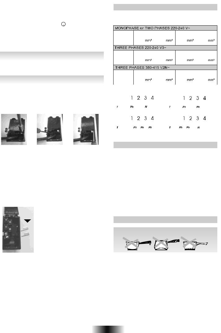
•Always use good quality cookware with perfectly flat and thick bases :
using this type of cookware will prevent hot spots that cause food to stick. Thick metal pots and pans will provide an even distribution of heat.
•Ensure that the base of the pot or pan is dry : when filling pans with liquid or using one that has been stored in the refrigerator, ensure that the base of the pan is completely dry before placing it on the hob. This will help to avoid staining the hob.
•Use pans whose diameter is wide enough to completely cover the surface unit : the size of the pan should be no smaller than the heating area.
If it is slightly wider the energy will be used at its maximum efficiency.
7 GB-IE
THE CHOICE OF COOKWARE - The following information will help you to choose cookware which will give good performance.
Stainless Steel : highly recommended. Especially good with a sandwich clad base. The sandwich base combines the benefits of stainless steel (appearance, durability and stability) with the advantages of aluminium or copper (heat conduction, even heat distribution).
Aluminium : heavy weight recommended. Good conductivity. Aluminium residues sometimes appear as scratches on the hob, but can be removed if cleaned immediately.
Because of its low melting point, thin aluminium should not be used.
Cast Iron : usable, but not recommended. Poor performance. May scratch the surface.
Copper Bottom / stoneware: heavy weight recommended. Good performance, but copper may leave residues which can appear as scratches. The residues can be removed, as long as the hob is cleaned immediately. However, do not let these pots boil dry. Overheated metal can bond to glass hobs. An overheated copper pot will leave a residue that will permanently stain the hob.
Porcelain/enamel : Good perfomance only with a thiny smooth, flat base.
Glass-ceramic : not recommended. Poor performance. May scratch the surface.
7. USE
• After powering up the hob, wait some seconds to activate the electronic controls.
-Press the button  .
.
Electronic control of the hob is activated. In each display zone
the heat level |
is displayed and the control LED blinks. |
-After 20 seconds whithout use, the electronic control goes off and the starting operation has to be repeated.
• STARTING A COOKING ZONE
- Press the selection button of the required cooking zone. In the display zone, the control LED is on steady. It shows that the zone is live.
-Press the - or + button to select a heat level between 1 and 9. Hold down the + or - button and the heat level increases or decreases gradually.
The following examples are for information only. Personal experience should then let you adapt these settings to your taste and habits.
0 |
: |
Off |
1 |
: |
) |
2: ) ..... Melting heat
3: Keeping hot
4: Heating up
5: Thawing, stewing, full cooking, low temperature cooking
6: Cooking without lid
7: Frying, meat browning and roasting
8: High temperature cooking and roasting, seizing
9: Frying, boiling large quantities of water.......
•STOPPING A COOKING ZONE
-Press the selection button of the required cooking zone.
-Press the - button to display heat level  . Now the zone goes off, the indicator
  goes off after 10 seconds.
-To stop rapidly, press the - and + buttons at the same time.
The heat level automatically goes down to .
The cooking zone goes off.
• GENERAL STOP |
|
|
|
|
The cooking zones and the timer can be stopped at any |
|
|
||
|
||||
moment by pressing the On-Off button. |
|
|
||
|
Downloaded |
|||
• RESIDUAL HEAT INDICATOR |
from |
|||
|
|
|||
The control panel tells the user when the surface temperature of |
||||
the cooking zones exceeds about 60°C, by the following displaying:
. When the temperature goes back below 60°C, the display |
|
goes off. |
www |
. |
|
For ending the cooking, we advise switching off thevandenborrecooking zone and using the residual heat of the zone to finish cooki g gently.
N.B. After a cut in the current, the residual heat indicator disappears completely, even if the surface temperature exceeds 60°C.
• OPERATING THE ADDITIONAL COOKING ZONE |
. |
(TWO ZONES) |
be |
The cooking zone with two zones is fitted certain models. It can be either concentric or extendable.
It is active in totality when the cooking zone is in function ; the control led of the additional cooking is displayed.
To desactivate the additional cooking zone :
-Press on the additional cooking zone button  . The corresponding control led for the additional cooking zone goes off when it is desactivated.
To re-activate the additional cooking zone :
-Press on the additional cooking zone button  . The corresponding control led for the additional cooking zone is active.
•OPERATING THE ADDITIONAL COOKING ZONE (THREE ZONES)
The additional cooking zone is fitted only one model.
It is active in totality when the cooking zone is in function ; the two control leds of the additional cooking are displayed.
To desactivate the additional cooking zones :
-Press one time the additional cooking zone button  . The corresponding control led for the external additional cooking zone goes off when it is desactivated.
-Press two times the additional cooking zone button  . The corresponding control led for the central additional cooking zone goes off when it is desactivated.
To re-activate the additional cooking zones :
-Press on the additional cooking zone button, one or two times on the additional cooking zone button, according to the need.
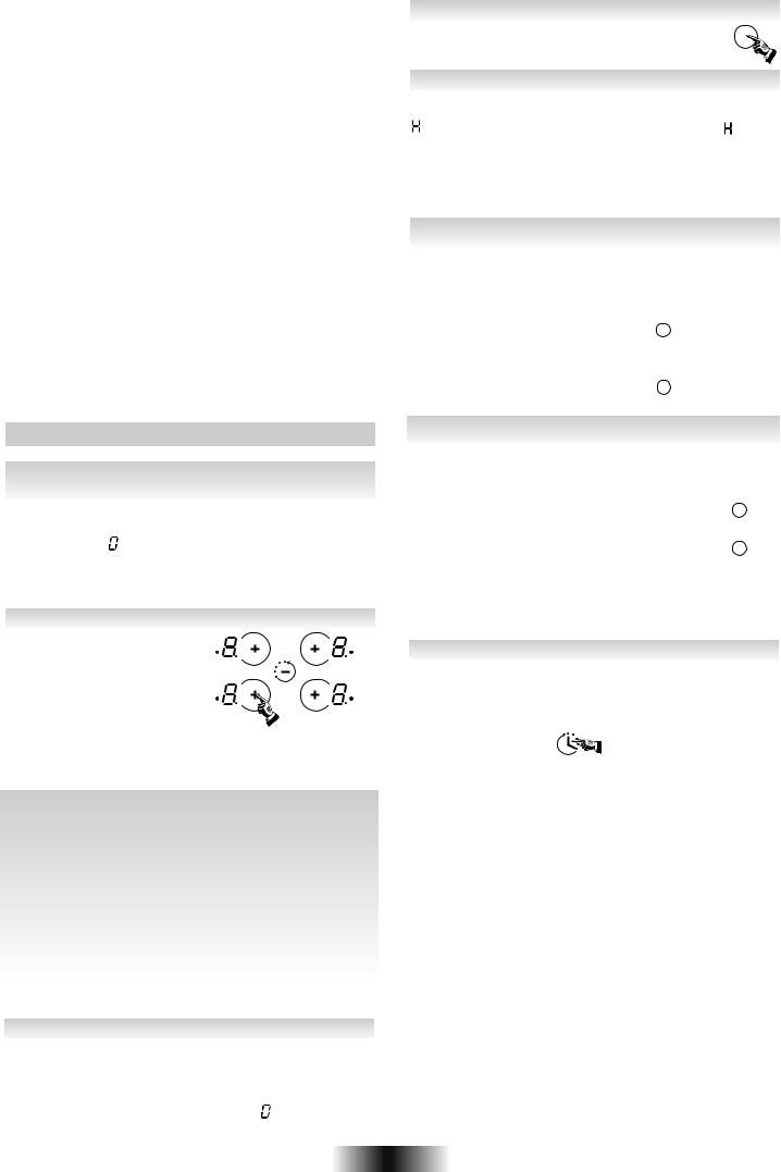
• PROGRAMMING A COOKING ZONE (according to the model)
Every cooking zone can be programmed for a maximum time of 99 minutes.
-Start the required zone by following the previous instructions. The control LED near the heat level must be displayed, it shows
that the zone is live.
- Press the Timer button.
The zone mark around the timer display shows the controlled zone.
-Press again on the timer button to select a time in minutes between 0 and 99 minutes or press on the "-" button to decrease the time between 60 minutes and 0.
 the programmed time can be modified at any moment reactivating the cooking zone and then the timer button.
When the time is run, the cooking zone goes off automatically and an audible beep sounds for 1 minute, press the timer button to stop it.
 the time can be used alone as reminder, it will ring at the end of the programmed time.
8 GB-IE
 Loading...