


Compresor de aire portátil |
FP2051, FP2052 |
|
|
Garantía Limitada
1.DURACIÓN: A partir de la fecha de compra por el comprador original tal como se especifica a continuación: Productos Estándard (Standard Duty) - Un año; Productos Resistentes (Serious Duty) -Dos años; Productos Robustos (Extreme Duty) - Tres años; Los compresores marca Maxus tienen una garantía de 5 (cinco) años.
2.QUIEN OTORGA ESTA GARANTÍA (EL GARANTE: Campbell Hausfeld / The Scott Fetzer Company 100 Production Drive, Harrison, Ohio 45030 Teléfono: (800) 543-6400
3.QUIEN RECIBE ESTA GARANTÍA (EL COMPRADOR): El comprador original (que no sea un revendedor) del producto Campbell Hausfeld.
4.PRODUCTOS CUBIERTOS POR ESTA GARANTÍA: Cualquier compresor de aire Campbell Hausfeld.
5.COBERTURA DE LA GARANTÍA: Los defectos substanciales de material y fabricación que ocurran dentro del período de validez de la garantía.
6.LO QUE NO ESTÁ CUBIERTO POR ESTA GARANTÍA:
A.Las garantías implícitas, incluyendo aquéllas de comerciabilidad e IDONEIDAD PARA FINES PARTICULARES, ESTÁN LIMITADAS A PARTIR DE LA FECHA DE COMPRA ORIGINAL DE ACUERDO CON LO ESPECIFICADO EN EL PÁRRAFO DE DURACIÓN. Si el compresor de aire es empleado para uso comercial (uso diario durante la operación normal de una empresa), industrial (funcionamiento diario en una fábrica), o para renta, la garantía será aplicable durante 90 (noventa) días a partir de la fecha de compra. La garantía de los compresores Robustos (Extreme Duty) no se limita a los
90(noventa) días cuando éstos se usen para trabajos de contratistas. La garantía de los compresores marca Maxus no se limita a los 90 (noventa) días cuando éstos se usen para trabajos comerciales y de contratistas. La garantía de los compresores de cuatro cilindros de una y dos etapas no se limita a los 90 (noventa días) cuando éstos se usen para trabajos comerciales o industriales. En algunos estados no se permiten las limitaciones a la duración de una garantía implícita, por lo cual las limitaciones antedichas pueden no ser aplicables en su caso.
B.CUALQUIER PÉRDIDA DAÑO INCIDENTAL, INDIRECTO O CONSECUENTE QUE PUEDA RESULTAR DE UN DEFECTO, FALLA O MALFUNCIONAMIENTO DEL PRODUCTO CAMPBELL HAUSFELD. En algunos estados no se permite la exclusión o limitación de daños incidentales o consecuentes, por lo tanto, en tales casos esta limitación o exclusión no es aplicable
C.Cualquier falla que resulte de un accidente, abuso, negligencia o incumplimiento de las instrucciones de funcionamiento y uso indicadas en el (los) manual(es) que se adjunta(n) al compresor.
D.Los servicios requeridos antes de la entrega tales como: ensamblaje, aceite o lubricantes y ajustes.
E.Artículos o servicios normalmente requeridos para el mantenimiento del producto, tales como:lubricantes, filtros, empaques, etc.
F.Los motores de gasolina están específicamante excluidos de la cobertura de esta garantía limitada. El comprador debe seguir las clausulas de la garantía otorgada por el fabricante del motor de gasolina que se suministra con el producto.
G.Artículos adicionales no cubiertos bajo esta garantía:
1.Todos los Compresores
a.Cualquier componente dañado durante el envío o cualquier daño ocasionado por haber instalado u operado la unidad bajo condiciones contrarias a lo indicado en las instrucciones para instalar u operar la unidad o daños ocasionados por el contacto con herramientas o los alrrededores.
b.Daños del cabezal o las válvulas ocasionados por la lluvia, humedad excesiva, agentes corrosivos u otros contaminantes.
c.Daños de apariencia que no afecten el funcionamiento del compresor.
d.Tanques oxidados, incluyendo pero no limitado al óxido debido al drenaje inadecuado u agentes corrosivos en el ambiente.
e.Motores eléctricos, válvulas de chequeo y presostatos después del primer año a partir de la fecha de compra.
f.Llaves de drenaje
g.Daños debidos al alambrado incorrecto o conexión a cicuitos con voltaje inadecuados para la unidad.
h.Otros artículos no enumerados pero considerados de desgaste general.
i.Presostatos, controles de flujo de aire y válvulas de seguridad cuyos parametros fijados de fábrica se modifiquen.
2.Compresores lubricados
a.Daños del cabezal o las válvulas debidos al uso de aceites no especificados.
b.Daños del cabezal o las válvulas debidos a cualquier contaminación del aceite o por no haber seguido las instrucciones de lubricación.
3.Compresores con bandas/ de accionamiento directo/ motores de gasolina
a.Bandas
b.Daños de los anillos debido al mantenimiento inadecuado del filtro.
c.Ajustes manuales de los instrumentos de carga/descarga y válvula de estrangulación.
7.RESPONSABILIDADES DEL GARANTE BAJO ESTA GARANTÍA: Reparar o reemplazar, como lo decida el Garante, el compresor o componentes que estén defectuosos, se hayan dañado o hayan dejado de funcionar adecuadamente, durante el período de validez de la garantía
8.RESPONSABILIDADES DEL COMPRADOR BAJO ESTA GARANTÍA:
A.Suministrar prueba fechada de compra y la historia de mantenimiento del producto.
B.Entregar o enviar los compresores de aire portátiles o componentes lal Centro de Servicio autorizado Campbell Hausfeld más cercano. Los gastos de flete, de haberlos, deben ser pagados por el comprador.
C.Tener cuidado al utilizar el producto, tal como se indica(n) en el (los) manual(es) del propietario.
9.CUÁNDO EFECTUARÁ EL GARANTE LA REPARACIÓN O REEMPLAZO CUBIERTO BAJO ESTA GARANTÍA: La reparación o reemplazo dependerá del flujo normal de trabajo del centro de servicio y de la disponibilidad de repuestos.
Esta garantía limitada es válida sólo en los EE.UU., Canadá y México y otorga derechos legales específicos. Usted también puede tener otros derechos que varían de un Estado a otro. o de un país a otro.
See Warranty on page 10 for important information about commercial use of this product.
Operating Instructions and Parts Manual |
FP2051, FP2052 |
|
|
Please read and save these instructions. Read carefully before attempting to assemble, install, operate or maintain the product described. Protect yourself and others by observing all safety information. Failure to comply with instructions could result in personal injury and/or property damage! Retain instructions for future reference.
Portable Air Compressor
Description
Oilless compressors are designed for do-it-yourselfers with a variety of home and automotive jobs. These units operate without oil. Compressed air from this unit will contain moisture. Install a water filter or air dryer if application requires dry air.
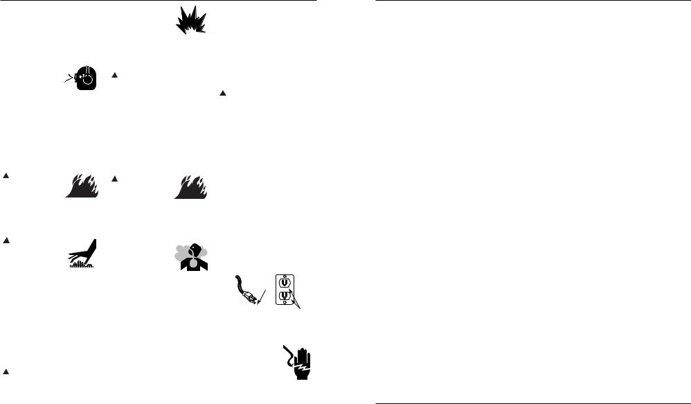
Safety Guidelines
This manual contains information that is very important to know and understand. This information is provided for SAFETY and to PREVENT EQUIPMENT PROBLEMS. To help recognize this information, observe the following symbols.
Danger indicates ! DANGER an imminently
hazardous situation which, if not avoided, WILL result in death or serious injury.
Warning indicates ! WARNING a potentially
hazardous situation which, if not avoided, COULD result in death or serious injury.
Caution indicates a ! CAUTION potentially
hazardous situation which, if not avoided, MAY result in minor or moderate injury.
Notice indicates NOTICE important
information, that if not followed, MAY cause damage to equipment.
Unpacking
After unpacking the unit, inspect carefully for any damage that may have occurred during transit. Make sure to tighten fittings, bolts, etc., before putting unit into service. In case of questions, damaged or missing parts,
DO NOT RETURN THE
PRODUCT TO THE STOP! RETAILER! CALL
1-800-543-6400
Record the Model No., Serial No. and date of purchase located on the base below the pump in the space below.
Model No. ____________________
Date Code ____________________
Date of purchase _________________
Retain these numbers for future reference.
please call 1-800-543-6400 for customer assistance.
Have the date code, model number, and parts list (with missing parts circled before calling.)
Do not operate ! WARNING unit if damaged
during shipping, handling or use. Damage may result in bursting and cause injury or property damage.
General Safety
Information
Since the air compressor and other components used (filters, lubricators, hoses, etc.), make up a high pressure
! DANGER
Breathable Air Warning
This compressor/pump is not equipped and should not be used “as is” to supply breathing quality air. For any application of air for human consumption, the air compressor/pump will need to be fitted with suitable in-line safety and alarm equipment. This additional equipment is necessary to properly filter and purify the air to meet minimal specifications for Grade D breathing as described in Compressed Gas Association Commodity Specification G 7.1 - 1966, OSHA 29 CFR 1910. 134, and/or Canadian Standards Associations (CSA).
DISCLAIMER OF WARRANTIES
In the event the compressor is used for the purpose of breathing air application and proper in-line safety and alarm equipment is not simultaneously used, existing warranties shall be voided, and Campbell Hausfeld disclaims any liability whatsoever for any loss, personal injury or damage.
pumping system, the following safety precautions must be observed at all times:
1. Read all manuals |
|
included with this |
|
product carefully. Be |
MANUAL |
thoroughly familiar with the controls and
the proper use of the equipment.
2.Follow all local electrical and safety codes as well as in the US, National Electrical Codes (NEC) and Occupational Safety and Health Act (OSHA).
REMINDER: Keep your dated proof of purchase for warranty purposes! Attach it to this manual or file it for safekeeping.
© 2004 Campbell Hausfeld/Scott Fetzer |
For parts, product & service information |
IN611602AV 8/04 |
visit www.chpower.com
Portable Air Compressor
General Safety |
|
|
|
|
|
|
|
|
Installation |
||||||||||||
|
! DANGER |
|
|
|
|
||||||||||||||||
Information (Continued) |
|
|
|
|
|
|
|
LOCATION |
|
|
|
|
|||||||||
Never attempt to repair |
|
|
|
|
|
|
|
||||||||||||||
|
3. Only persons well acquainted with |
or modify a tank! |
|
|
|
|
|
It is extremely important to use the |
|||||||||||||
|
these rules of safe operation should |
Welding, drilling or any |
|
|
|
compressor in a clean, well ventilated |
|||||||||||||||
|
other modification will weaken the |
|
|
||||||||||||||||||
|
be allowed to use the compressor. |
|
|
area where the surrounding air |
|||||||||||||||||
|
tank resulting in damage from rupture |
|
|
||||||||||||||||||
|
4. Keep visitors away and NEVER allow |
or explosion. Always replace worn or |
|
|
temperature will not be more than 100°F. |
||||||||||||||||
|
children in the work area. |
damaged tanks. |
|
|
|
|
|
A minimum clearance of 18 inches |
|||||||||||||
|
5. Wear safety glasses |
|
|
|
|
Drain liquid from |
|
|
between the compressor and a wall is |
||||||||||||
|
|
|
|
|
|
|
|
|
|||||||||||||
|
and use hearing |
|
|
|
|
|
! WARNING |
|
tank daily. |
|
|
required because objects could obstruct |
|||||||||
|
protection when |
|
|
|
|
13. Tanks rust from moisture build-up, |
|
|
air flow. |
|
|
|
|
||||||||
|
operating the pump |
|
|
|
|
|
|
|
|
Do not locate the |
|||||||||||
|
or unit. |
|
|
|
|
|
which weakens the tank. Make sure |
|
|
|
! CAUTION |
|
compressor air |
||||||||
|
6. Do not stand on or use the pump or |
|
to drain tank daily and inspect |
|
|
inlet near steam, paint spray, sandblast |
|||||||||||||||
|
|
periodically for unsafe conditions |
|
|
areas or any other source of |
||||||||||||||||
|
unit as a handhold. |
|
|
|
|||||||||||||||||
|
|
such as rust formation and |
|
|
contamination. This debris will damage |
||||||||||||||||
|
7. Before each use, inspect compressed |
|
|
|
|||||||||||||||||
|
|
corrosion. |
|
|
|
|
|
the motor. |
|
|
|
|
|||||||||
|
air system and electrical components |
|
|
|
|
|
|
|
|
|
|
|
|
|
|||||||
|
14. Fast moving air will stir up dust and |
|
|
|
|
|
|
|
|
|
|||||||||||
|
for signs of damage, deterioration, |
|
|
GROUNDING INSTRUCTIONS |
|||||||||||||||||
|
|
debris which may be harmful. Release |
|
|
|||||||||||||||||
|
weakness or leakage. Repair or |
|
|
|
|||||||||||||||||
|
|
|
|
|
|
|
|
|
|
|
|||||||||||
|
|
air slowly when draining moisture or |
|
|
1. This product is for use on a nominal |
||||||||||||||||
|
replace defective items before using. |
|
|
|
|||||||||||||||||
|
|
depressurizing the compressor system. |
|
|
|
120 volt circuit and has a grounding |
|||||||||||||||
|
8. Check all fasteners at frequent |
|
|
|
|
||||||||||||||||
|
|
|
|
|
|
|
|
|
|
plug that looks like the plug illustrated |
|||||||||||
|
intervals for proper tightness. |
|
|
|
|
|
|
|
|
|
|||||||||||
|
SPRAYING PRECAUTIONS |
|
|
|
in Fig. 1. Make sure the product is |
||||||||||||||||
|
|
|
|
|
|
|
|
|
|
||||||||||||
|
|
|
|
|
|
|
|
|
|
|
|
|
|
|
|
connected to an outlet having the |
|||||
|
! WARNING |
|
|
|
|
|
|
! WARNING |
|
|
|
|
|
|
|
same configuration as the plug. This |
|||||
Motors, electrical |
|
|
|
|
|
|
|
|
|
|
|
|
|||||||||
|
|
|
|
Do not spray flammable |
|
|
|
|
|
product must be grounded. In the |
|||||||||||
equipment and controls |
|
|
|
|
|
|
|
|
|||||||||||||
|
materials in vicinity of |
|
|
|
|
|
event of an electrical short circuit, |
||||||||||||||
can cause electrical arcs |
|
|
|
|
|
|
|
|
|||||||||||||
|
open flame or near |
|
|
|
|
|
|
grounding reduces risk of electrical |
|||||||||||||
that will ignite a flammable gas or |
|
|
|
|
|
|
|||||||||||||||
|
|
|
|
||||||||||||||||||
ignition sources including the |
|
|
|
shock by providing an escape wire for |
|||||||||||||||||
vapor. Never operate or repair in or |
|
|
|
||||||||||||||||||
compressor unit. |
|
|
|
|
|
|
|||||||||||||||
near a flammable gas or vapor. Never |
|
|
|
|
|
|
electric current. This product is |
||||||||||||||
15. Do not smoke when spraying paint, |
|
|
|
||||||||||||||||||
store flammable liquids or gases in the |
|
|
|
equipped with a cord having a |
|||||||||||||||||
vicinity of the compressor. |
|
insecticides, or other flammable |
|
|
|
||||||||||||||||
|
|
|
|
grounding wire with an appropriate |
|||||||||||||||||
|
|
|
|
|
|
|
|
substances. |
|
|
|
|
|
|
|||||||
|
|
|
|
|
|
|
|
|
|
|
|
|
|
grounding plug. Plug must be plugged |
|||||||
|
! CAUTION |
|
|
|
|
|
16. Use a face mask/ |
|
|
|
|
|
|
into an outlet that is properly installed |
|||||||
|
|
|
|
|
|
|
|
|
|
|
|
||||||||||
Compressor parts may |
|
|
|
|
|
|
|
|
|
||||||||||||
|
|
respirator when |
|
|
|
|
|
|
and grounded in accordance with all |
||||||||||||
be hot even if the unit |
|
|
spraying and spray in |
|
|
|
|
local codes and ordinances. |
|||||||||||||
is stopped. |
|
|
|
|
|
|
|
|
|
||||||||||||
|
|
|
|
|
a well ventilated area |
|
|
|
|
|
|
|
|
|
|
||||||
|
|
|
|
|
|
|
|
|
|
|
|
|
|
|
|
|
|
||||
|
|
|
|
|
|
|
|
to prevent health and |
|
|
|
|
|
|
|
|
|
|
|||
9. Keep fingers away from a running |
|
|
|
|
|
|
|
|
|
|
|||||||||||
|
fire hazards. |
|
|
|
|
|
|
Grounding |
|||||||||||||
|
compressor; fast moving and hot |
|
|
|
|
|
|
|
|||||||||||||
|
17. Do not direct paint or other sprayed |
|
|
|
Pin |
|
|
|
|
||||||||||||
|
parts will cause injury and/or burns. |
|
|
|
|
TEST RESET |
|
||||||||||||||
|
|
|
|
|
|
|
|
||||||||||||||
|
|
material at the compressor. Locate |
|
|
|
|
|
|
|
|
|
||||||||||
10. If the equipment should start to |
|
|
|
|
|
|
|
|
|
|
|||||||||||
|
compressor as far away from the |
|
|
|
|
|
|
|
|
|
|||||||||||
|
abnormally vibrate, STOP the |
|
|
|
|
|
|
|
|
|
|
||||||||||
|
|
spraying area as possible to |
|
|
|
|
|
Grounded Outlet |
|||||||||||||
|
engine/motor and check |
|
|
|
|
|
|
||||||||||||||
|
|
minimize overspray accumulation |
|
|
|
|
|
||||||||||||||
|
|
|
|
|
|
|
|
|
|
|
|||||||||||
|
immediately for the cause. Vibration |
|
|
|
|
|
|
|
|
|
|
||||||||||
|
|
on the compressor. |
|
|
|
|
|
|
|
|
|
||||||||||
|
is generally a warning of trouble. |
|
|
|
|
|
|
|
|
|
|
||||||||||
|
18. When spraying or cleaning with |
|
|
Figure 1 - Grounding Method |
|||||||||||||||||
11. To reduce fire hazard, keep |
|
|
|||||||||||||||||||
|
solvents or toxic chemicals, follow |
|
|
|
|
|
|
|
|
|
|||||||||||
|
engine/motor exterior free of oil, |
|
the instructions provided by the |
|
|
|
|
|
|
|
|
|
|||||||||
|
solvent, or excessive grease. |
|
chemical manufacturer. |
|
|
|
! DANGER |
|
|
|
|
|
|||||||||
|
|
|
|
Improper use of |
|
|
|
|
|||||||||||||
|
|
|
|
|
|
|
|
|
|
|
|
|
|
|
|
|
|
|
|||
|
|
|
Never remove or |
|
|
|
|
|
|
|
|
grounding plug can |
|
|
|
|
|||||
|
! WARNING |
|
attempt to adjust |
|
|
|
|
|
|
|
|
result in a possible risk |
|
||||||||
safety valve. Keep safety valve free |
|
|
|
|
|
|
|
|
of electrical shock! |
|
|
|
|
||||||||
|
|
|
|
|
|
|
|
|
|
|
|
|
|
|
|||||||
from paint and other accumulations. |
|
|
|
|
|
|
|
|
|
|
|
|
|
|
|
||||||
|
|
|
|
|
|
|
|
|
|
|
|
|
|
|
|
|
|
|
|
||
www.chpower.com |
|
|
|
|
|
|
|
|
|
|
|
|
|
|
|
|
|
|
|
||
FP2051, FP2052
Lista de Repuestos |
FP2051, FP2052 |
No. de |
Número del |
|
|
Ref. Descripción |
repuesto |
Ctd. |
|
|
|
|
|
1 |
Cabezal/motor |
FP205110AV |
1 |
2 |
Patas del chasis |
■ |
4 |
3 |
Patas de la cubierta del motor |
▲ |
4 |
4 |
Cubierta izquierda del compresor |
FP205111AV |
1 |
5 |
Cubierta derecha del compresor |
FP205112AV |
1 |
6 |
Panel del manómetro |
FP205113AV |
1 |
7 |
Chasis |
FP205114AV |
1 |
8 |
Mango |
FP205115AV |
1 |
9 |
Distribuidor (incluye regulador) |
FP205116AV |
1 |
10 |
Bandeja de accesorios |
FP205117AV |
1 |
11 |
Tubo de escape |
|
1 |
12 |
Soporte de montaje para pared |
● |
1 |
13 |
Tornillo 1/4x19 |
■ |
4 |
14 |
Tornillo M6x15 |
■ |
4 |
|
|
▼ |
4 |
15 |
Tornillo M6x200 |
▼ |
1 |
16 |
Presostato |
FP205118AV |
1 |
17 |
Tablero del circuito |
|
1 |
18 |
Cordón eléctrico |
∆ |
1 |
19 |
Conexión de compresión |
|
2 |
20 |
Tuerca de compresión |
|
2 |
21 |
Manga |
|
2 |
22 |
Arandela de 6,4 mm (1/4”) |
|
|
|
(No se muestra) |
■ |
4 |
|
|
▼ |
4 |
23 |
Interruptor de encendido/apagado FP205129AV |
1 |
|
24 |
Válvula de drenaje |
D-1403 |
1 |
25 |
Accesorios de inflado |
|
1 |
26 |
Adaptador |
|
1 |
27 |
Boquilla para neumático |
|
1 |
28 |
Tuerca de retención de la cubierta ▼ |
1 |
|
29 |
Tornillo 3x8 |
▼ |
5 |
30 |
Tornillo de fijación para hormigón |
● |
3 |
31 |
Valvula de chequeo |
† |
1 |
32 |
Resorte |
† |
1 |
33 |
Manómetro de salida |
FP006300AV |
1 |
34 |
Manómetro del tanque |
GA016304AV |
1 |
35 |
Tornillo M3x10 |
|
2 |
|
|
|
|
No. de |
Número del |
|
|
Ref. Descripción |
repuesto |
Ctd. |
|
|
|
|
|
36 |
Tuerca M3x2,5 |
|
2 |
37 |
Arandela |
|
2 |
38 |
Ventilador |
|
1 |
39 |
Alivio de tensión |
∆ |
1 |
40 |
Tornillo M4x8 |
∆ |
2 |
41 |
Tornillo M3x10 |
|
2 |
42 |
Sujetador del cableado |
|
1 |
43 |
Valvula de seguridad |
V-215105AV |
1 |
44 |
Gancho de la correa |
|
1 |
45 |
Correa |
|
1 |
46 |
Tornillo M4x10 |
|
1 |
47 |
Fusible |
FP205130AV |
1 |
48 |
Tornillo autorroscante |
▲ |
1 |
49 |
Tubo de goma |
▲ |
2 |
50 |
Tornillo |
▲ |
1 |
51 |
Tuerca |
▲ |
4 |
52 |
Placa fija del motor |
▲ |
1 |
53 |
Tuerca |
▲ |
1 |
54 |
Tornillo para madera |
● |
3 |
|
|
|
|
JUEGOS DE REPUESTOS |
|
|
|
▲ |
Juego de montaje del motor |
FP205131AV |
|
■ |
Juego de las patas del chasis |
FP205120AV |
|
● |
Juego de montaje para pared |
FP205121AV |
|
|
Juego de tubos |
FP205122AV |
|
▼ |
Juego de tornillos de la cubierta |
FP205123AV |
|
|
Juego del tablero de circuitos |
FP205124AV |
|
∆ |
Juego del cordón de corriente |
FP205125AV |
|
† |
Juego de la válvula de chequeo |
FP205126AV |
|
|
Juego del ventilador |
FP205127AV |
|
|
Juego de la correa |
FP205128AV |
|
|
Kit de herramienta |
FP204008AV |
|
|
Juego para calcomanía (No se muestra) |
|
|
|
Modelo FP2051 |
FP205132AV |
|
|
Modelo FP2052 |
FP205221AV |
|
|
|
|
|
27 Sp
2

Compresor de aire portátil
Para Ordenar Repuestos Sírvase Llamar al Distribuidor Más Cercano a su Domicilio
Sírvase darnos la siguiente información: |
|
|
|
|
Puede escribirnos a: |
-Número del modelo |
|
|
|
|
Campbell Hausfeld / Attn: Parts Department |
-Número de Serie (de haberlo) |
|
|
|
|
100 Production Drive |
-Descripción y número del repuesto según la lista de repuestos |
|
|
Harrison, OH 45030 U.S.A. |
||
|
23 |
|
|
|
|
6 |
|
|
|
|
|
15 |
|
|
|
42 |
|
|
|
|
41 |
|
|
|
|
|
|
|
|
|
|
|
|
47 |
|
|
|
|
|
|
8 |
|
|
|
|
|
17 |
4 |
|
|
|
|
|
|
37 |
|
|
|
|
29 |
|
|
38 |
|
1 |
|
|
|
|
||
35 36 |
11 |
|
|
|
|
43 |
|
|
|
|
|
|
|
21 19 |
|
|
|
34 |
20 |
|
|
|
|
|
20 |
|
18 |
||
|
21 |
50 |
|||
33 |
|
48 |
|||
19 |
|
49 |
|
|
|
|
|
51 |
|||
|
32 |
|
|
||
9 |
|
|
3 |
5 |
|
|
|
|
|||
|
31 |
|
|
|
|
16 |
|
|
|
|
40 |
|
|
|
|
|
28 |
|
|
|
|
|
39 |
|
|
|
|
|
52 |
|
|
|
|
|
53 |
|
|
|
|
|
14 |
|
|
|
|
46 |
|
25 |
|
|
|
45 |
|
27 |
|
|
|
|
|
|
|
|
|
24 |
|
27 |
|
|
|
|
12 |
10 |
|
|
|
|
30 |
|
|
|
|
|
44 |
7 |
|
|
|
|
54 |
2 |
|
|
|
|
|
13 |
|
|
|
|
FP2051, FP2052 |
|
|
|
|
|
|
FP2051, FP2052
Installation (Continued)
! DANGER Do not use a grounding adapter with this product!
2.If repair or replacement of cord or plug is necessary, do not connect grounding wire to either flat blade terminal. The wire with insulation having an external surface that is green (with or without yellow stripes) is the grounding wire.
|
Never connect |
|
! WARNING |
||
green (or green and |
yellow) wire to a live terminal.
3.Check with a qualified electrician or serviceman if grounding instructions are not completely understood, or if in doubt as to whether product is properly grounded. Do not modify plug provided; if it will not fit outlet, have proper outlet installed by a qualified electrician.
! CAUTION |
Overheating, short |
circuiting and fire |
damage will result from inadequate wiring, etc.
WALL MOUNTING
This compressor can be mounted to the wall for convenient storage. It can also be operated while in the hanging position.
Before mounting, select a location at a wall stud or on a concrete surface. Make sure that the mounting area measures at least 24” x 30”.
Hang compressor on ! WARNING a properly installed
hanger sturdy enough to support compressor’s weight (approximately 25 pounds). Do not hang on peg board, wallboard, or any structure not suited to hold compressor’s weight.
Mounting hanger bracket
For mounting to a wood stud, the bracket has three holes in the center. These holes are located in between the two mounting hooks that attach to the back of the compressor. Use a stud finder to locate the center of the stud.
Tank gauge |
Safety valve |
On/off switch
Outlet gauge
 Regulator
Figure 2 - Unit Identification
Use the screws provided to attach the bracket to the wall. Make sure to mount to the wood stud, not just to drywall.
For mounting to a concrete surface, pre-drill holes in the concrete and insert the anchors that are provided. Align the holes in the bracket with the wall anchors and use the three screws provided to attach the bracket to the wall.
Avoid mounting compressor to drywall or gypsum board unless screws are lagged into wood studs.
Mounting air compressor to bracket
There are three mounting hooks on the wall hanging bracket. On the back of the compressor shroud, there is an opening that serves as a handle. The two hooks on the top of the bracket fit in the handle opening on the compressor shroud. The remaining hook on the bottom of the bracket fits into the lower part of the compressor shroud, below the handle opening.
HOSE STORAGE
1.Attach one of the threaded ends of recoil hose to air outlet on front of
Extension cords for 120V/2.5 Amp Unit
compressor.
2.Route recoil hose to side of tank where hose strap is located.
3.Loosen lower end of hose strap.
4.Slide as much of recoil as possible onto hose strap.
5.Reattach hose strap to compressor.
Operation
Definition of Terms
Regulator - The regulator controls the amount of air pressure released at the hose outlet.
ASME Safety Valve - This valve automatically releases air if the tank pressure exceeds the preset maximum.
Handle - Designed to move the compressor.
Drain Valve - This valve is located on the bottom of the tank. Use this valve to drain moisture from the tank daily to reduce the risk of corrosion.
Reduce tank pressure below 10 psi, then drain moisture from tank daily to avoid tank corrosion. Drain moisture
Length of Cord (ft) |
25 |
50 |
100 |
150 |
200 |
250 |
300 |
400 |
500 |
Gauge of Cord |
18 |
18 |
16 |
14 |
14 |
12 |
12 |
10 |
10 |
www.chpower.com
26 Sp |
3 |
Portable Air Compressor
Operation (Continued)
from tank by opening the drain valve located underneath the tank.
LUBRICATION
This is an oilless product and DOES NOT require lubrication to operate.
BEFORE FIRST START-UP
BREAK-IN PROCEDURE
(Complete this procedure before using compressor for the first time. Once completed, it is not necessary to repeat.)
1.Turn regulator knob fully clockwise (to the right) to open air flow.
2.Turn on/off switch to OFF position.
3.Plug in power cord.
4.Turn on/off switch to ON position and run compressor for 5 minutes.
5.Turn on/off switch to OFF position.
6.Unplug power cord.
The compressor is now ready for use.
BEFORE EACH START-UP
OPERATING PROCEDURE
1.Turn regulator knob fully counterclockwise (to the left) to close air flow.
2.Connect air hose to outlet of regulator.
3.Turn on/off switch to OFF position.
4.Plug in power cord.
5.Turn on/off switch to ON position and let compressor run until it reaches automatic shutoff pressure.
6.Attach tire chuck or tool to end of hose.
7.Turn regulator knob clockwise (to the right) to desired pressure of tool being used.
On/Off cycling of compressor
In the ON position, the compressor pumps air into the tank. When a shutoff (preset “cut-out”) pressure is reached, the compressor automatically shuts off.
MOISTURE IN COMPRESSED AIR
Moisture in compressed air will form into droplets as it comes from an air compressor pump. When humidity is high or when a compressor is in continuous use for an extended period of time, this moisture will collect in the tank. When using a paint spray or sandblast gun, this water will be carried from the tank through the hose, and out of the gun as droplets mixed with the spray material.
IMPORTANT: This condensation will cause water spots in a paint job, especially when spraying other than water based paints. If sandblasting, it will cause the sand to cake and clog the gun, rendering it ineffective. A filter in the air line (MP3105), located as near to the gun as possible, will help eliminate this moisture.
If the compressor is left in the ON position and air is depleted from the tank by use of a tire chuck, tool, etc., the compressor will restart automatically at its preset “cut-in” pressure. When a tool is being used continuously, the compressor will cycle on and off automatically.
In the OFF position, the pressure switch cannot function and the compressor will not operate. Make sure switch is in OFF position when connecting or disconnecting power cord from electrical outlet.
ASME SAFETY VALVE
|
! WARNING |
Do not remove or |
|
attempt to adjust |
|
the safety valve! |
|
|
3.The safety valve should automatically close at approximately 40-50 psi. If the safety valve does not allow air to be released when you pull on the ring, or if it does not close automatically, it MUST be replaced.
REGULATOR KNOB
1.This knob controls air pressure to an air operated tool or tire chuck.
2.Turn knob clockwise to increase air pressure.
3.To lower air pressure turn knob counterclockwise.
4.Turn fully counterclockwise to shut off flow of air completely.
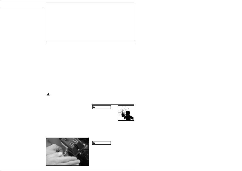
Check the safety valve by performing the following steps:
1.Plug the compressor in and run until shut off pressure is reached (see Operating Procedure).
2.Wearing safety glasses, pull the ring on the safety valve to release pressure from compressor tank. Use your other hand to deflect fastmoving air from being directed toward your face. See Figure 3.
Figure 3
Maintenance
! WARNING
Disconnect power source then release all pressure from the system before attempting to install,
service, relocate or perform any maintenance.
Check compressor often for any visible problems and follow maintenance procedures each time compressor is used.
Safety valve must ! WARNING be replaced if it
cannot be actuated or it leaks air after ring is released.
1.Turn compressor off and release pressure from system. (To release pressure from system, pull ring on ASME safety valve. Deflect escaping air by shielding valve with one hand
www.chpower.com
|
|
|
|
|
|
FP2051, FP2052 |
|
|
|
Guía de diagnóstico de averías |
|
|
|
|
|
||
|
|
|
|
|
|
|
|
|
|
Problema |
Posible(s) Causa(s) |
Acción a tomar |
|
|
|||
|
El compresor no funciona |
1. |
El interruptor está en la posición OFF |
1. Asegúrese de que el compresor esté enchufado y que el |
|
|||
|
|
|
(apagado) |
|
interruptor esté en la posición ON (encendido) |
|
||
|
|
2. |
No hay corriente eléctrica en el |
2. Revise el disyuntor o fusible en el panel de electricidad. |
|
|||
|
|
|
tomacorriente de la pared |
|
|
|
|
|
|
|
3. |
El compresor alcanzó la presión de corte |
3. Libere aire del tanque hasta que el compresor se reinicie |
|
|||
|
|
|
automático |
|
automáticamente. |
|
|
|
|
|
4. |
Motor recalentado |
4. Deje que el compresor se enfríe durante aproximadamente |
|
|||
|
|
|
|
|
30 minutos para que el interruptor térmico de sobrecarga |
|
||
|
|
|
|
|
vuelva a su posición normal. Asegúrese de que el compresor |
|
||
|
|
|
|
|
esté funcionando en un área limpia y bien ventilada donde |
|
||
|
|
|
|
|
la temperatura no exceda los 100ºF. |
|
|
|
|
|
5. |
Fusible quemado (dentro de la cubierta de |
5. Desconecte el compresor de la fuente de energía y luego |
|
|||
|
|
|
la bomba) |
|
quite la cubierta de la bomba. Fusible de repuesto: Pieza Nº |
|
||
|
|
|
|
|
FP205130AV. Si se quema el fusible de repuesto, llame al 1- |
|
||
|
|
|
|
|
800-543-6400. |
|
|
|
|
|
6. |
Interruptor de presión defectuoso |
6. Cambie el interruptor de presión |
|
|
||
|
|
|
|
|
|
|||
|
El protector térmico de |
1. |
Falta de ventilación adecuada/ |
1. Mueva el compresor a un área limpia y bien ventilada |
|
|||
|
sobrecarga detiene el |
|
temperatura ambiente demasiado alta |
|
donde la temperatura no exceda los 100ºF. |
|
||
|
funcionamiento |
2. |
Fallaron las válvulas del compresor |
2. |
Cambie el ensamblaje de la bomba |
|
|
|
|
reiteradamente |
|
|
|
|
|
|
|
|
|
|
|
|
|
|
|
|
|
Golpeteos, zumbidos, |
1. |
El tanque no está nivelado |
1. |
Nivele el tanque |
|
|
|
|
vibración excesiva. |
2. |
Cojinete defectuoso en la excéntrica o en |
2. Cambie el ensamblaje de la bomba |
|
|
||
|
|
|
el eje del motor |
|
|
|
|
|
|
|
3. |
El aro del cilindro o pistón está desgastado |
3. |
Cambie el ensamblaje de la bomba |
|
|
|
|
|
|
o marcado |
|
|
|
|
|
|
|
|
|
|
|
|
|
|
|
La presión del tanque |
1. |
Válvula de drenaje floja |
1. |
Apriete la válvula de drenaje |
|
|
|
|
disminuye cuando se |
2. |
Fugas en la válvula de retención |
2. Cambie la válvula de retención |
|
|
||
|
apaga el compresor |
3. |
Conexiones flojas (accesorios, tubería, etc.) |
3. Revise todas las conexiones con una solución de agua y |
|
|||
|
|
|
|
|
jabón. Si se detecta una fuga, apriete. O quite la conexión y |
|
||
|
|
|
|
|
aplique cinta para tuberías a las rocas y vuelva a armar. |
|
||
|
|
|
|
|
! PELIGRO |
|
No desarme la válvula |
|
|
|
|
|
|
|
de retención. Si hay |
|
|
|
|
|
|
|
|
|
||
|
|
|
|
aire en el tanque, primero purgue el tanque. |
|
|||
|
|
|
|
|
|
|
||
|
El compresor funciona en |
1. |
Uso excesivo de aire, el compresor es |
1. |
Disminuya el uso o compre una unidad que ofrezca una |
|
||
|
forma continua y la salida |
|
demasiado pequeño |
|
entrega de aire mayor (SCFM) |
|
|
|
|
de aire es más baja que la |
2. |
Conexiones flojas (accesorios, tubería, etc.) |
2. |
Revise todas las conexiones con una solución de agua y |
|
||
|
presión de descarga |
|
|
|
jabón. Si se detecta una fuga, apriete. O quite la conexión y |
|
||
|
normal/baja. |
3. |
Válvulas de entrada averiadas |
|
aplique cinta para tuberías a las rocas y vuelva a armar. |
|
||
|
|
3. |
Cambie el ensamblaje de la bomba |
|
|
|||
|
|
4. |
Aro del pistón desgastado |
4. |
Cambie el ensamblaje del pistón |
|
|
|
|
|
|
|
|
|
|
||
|
Exceso de humedad en el |
1. |
Demasiada agua en el tanque |
1. |
Drene el tanque, incline el tanque para eliminar la |
|
||
|
aire de descarga |
2. |
Humedad elevada |
|
humedad |
|
|
|
|
|
2. |
Llévelo a un área menos húmeda, utilice un filtro de aire de |
|
||||
|
|
|
|
|
línea |
|
|
|
|
|
|
|
|
Nota: La condensación de agua no es una causa para el |
|
||
|
|
|
|
|
malfuncionamiento del compresor. |
|
|
|
|
|
|
|
|
|
|
|
|
|
El compresor funciona en |
1. |
Presostato defectuoso |
1. |
Cambie el interruptor de presión |
|
|
|
|
forma continua y la |
2. |
Válvula de seguridad defectuosa |
2. |
Cambie la válvula de retención con un repuesto original |
|
||
|
válvula de seguridad se |
|
|
|
|
|
|
|
|
abre cuando aumenta la |
|
|
|
|
|
|
|
|
presión |
|
|
|
|
|
|
|
|
|
|
|
|
|
|
|
|
|
Arranques y paradas |
1. |
Demasiada condensación en el tanque |
1. |
Drene con más frecuencia |
|
|
|
|
excesivas |
2. |
Conexiones flojas (accesorios, tubería, etc.) |
|
|
|
|
|
|
|
|
|
2. |
Revise todas las conexiones con una solución de agua y |
|
||
|
|
|
|
|
jabón. Si se detecta una fuga, apriete. O quite la conexión y |
|
||
|
|
|
|
|
aplique cinta para tuberías a las rocas y vuelva a armar. |
|
||
|
|
|
|
|
|
|
|
|
4 |
25 Sp |
Compresor de aire portátil
Funcionamiento
(Continuación)
anillo o si no se cierra automáticamente, DEBE ser reemplazada.
PERILLA DEL REGULADOR
1.Esta perilla controla la presión de aire hacia una herramienta neumática o inflador para numáticos.
2.Gire la perilla en el mismo sentido de las agujas del reloj para aumentar la presión de aire.
3.Para disminuir la presión de aire, gire la perilla en sentido contrario a las agujas del reloj.
4.Gire la perilla totalmente en sentido contrario a las agujas del reloj para cerrar el flujo de aire completamente.
Mantenimiento
! ADVERTENCIA


Desconecte el cordón  eléctrico del tomacorrientes y
libere toda la presión del sistema antes de tratar de instalar, darle servicio, cambiar de lugar o darle cualquier tipo de mantenimiento.
Este compresor se debe chequear con frecuencia para ver si tiene algún tipo de problemas y le debe dar el siguiente mantenimiento antes de cada uso.
! ADVERTENCIA Debereempla- zar la válvula de seguridad si no la puede activar o si hay fugas de aire una vez que haya soltado el anillo.
1. Apague el compresor y libere la presión del sistema. (Para liberar la presión del sistema, tire del anillo de la válvula de seguridad ASME. Desvíe el aire cubriendo la válvula con una mano mientras tira del anillo con la otra mano.) Tire del anillo hasta vaciar el tanque.
Cuando se abra la
válvula de seguridad con presión en el tanque, se liberará una gran cantidad de aire que se mueve a gran velocidad. Use gafas de seguridad Z87.1 aprobadas por ANSI.
2.Drene la humedad del tanque abriendo la válvula de drenaje debajo del tanque. Incline el tanque para eliminar toda la humedad. Vea la Figura 4.
Figura 4
3.Limpie el polvo y la suciedad del tanque, las líneas de aire y la cubierta
de la bomba, mientras el compresor continúa apagado (OFF).
LUBRICACION
Este compresor no requiere lubricación.
PROTECTOR TERMICO
Este compre-
sor está equipado con un protector automático contra sobrecarga térmica que apagará el motor cuando éste se sobrecaliente.
Si el protector térmico de sobrecarga apaga el motor frecuentemente, asegúrese de que el compresor se utiliza en un área limpia y bien ventilada donde la temperatura no supera los 100ºF.
Debe esperar a
que el motor se enfríe antes de encenderlo. El motor se encenderá automáticamente, sin previo aviso, si lo deja conectado al tomacorrientes y enciende la unidad.
ALMACENAMIENTO
1.Drene la humedad del tanque.
2.Cuando no esté en uso, guarde el compresor en un lugar fresco y seco.
3.Desconecte la manguera y cuélguela con los extremos abiertos hacia abajo, para permitir que drene toda la humedad.
Notas
FP2051, FP2052
Maintenance
(Continued)
as you pull ring with other hand.) Pull ring until tank is empty.
A large amount of ! CAUTION fast moving air will
be released when the safety valve is opened with pressure in the tank. Wear ANSI approved Z87.1 safety glasses.
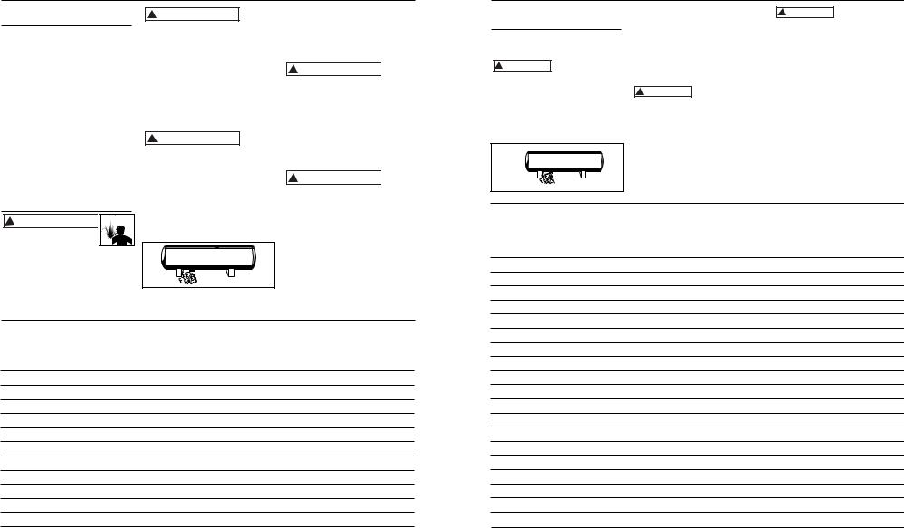
2.Drain moisture from tank by opening drain valve underneath tank. Tilt tank to remove all moisture. See Figure 4.
3.Clean dust and dirt from tank, air lines and pump cover while compressor is still OFF.
LUBRICATION
This is an oilless type compressor requiring no lubrication.
THERMAL OVERLOAD PROTECTOR
This compressor is ! CAUTION equipped with an
automatic reset thermal overload protector which will shut off motor if it becomes overheated.
If thermal overload protector shuts motor OFF frequently, make sure that the compressor is used in a clean, wellventilated area where temperature will not exceed 100° F.
If the thermal
! CAUTION overload protector is actuated, the motor must be allowed to cool down before start-up is possible. The motor will automatically restart without warning if left plugged into electrical outlet and unit is turned on.
STORAGE
1.Drain tank of moisture.
2.When not in use, store compressor in a cool dry place.
3.Disconnect hose and hang open ends down to allow any moisture to drain.
Figure 4
Notes
www.chpower.com
24 Sp |
5 |
 Loading...