


WG2060
Please read and save these instructions. Read carefully before attempting to assemble, install, operate or maintain the product described.
Protect yourself and others by observing all safety information. Failure to comply with instructions could result in personal injury and/or
property damage! Retain instructions for future reference.
IN972700AV 11/04
Operating Instructions & Parts Manual Models WG2060 and WG2064
Wire Feed
Arc Welder
Description
This Campbell Hausfeld wire feed welder
is designed to be used on standard 115V
household current. The welder is
equipped with infinite wire speed
control to accurately select the proper
wire feed rate needed for various
welding conditions. Internal components
are thermostatically protected.
This welding system is designed for use
with the Flux Cored Arc Welding
(FCAW) or the Gas Metal Arc Welding
(GMAW) process. As delivered from the
factory, this welder can weld with .024”
(.6mm) to .030” (.8mm) diameter wire in
MIG and .030” (.8mm) to .035” (.9mm)
diameter wire in flux core. A starter
spool of .035” (.9mm) flux cored wire is
included.
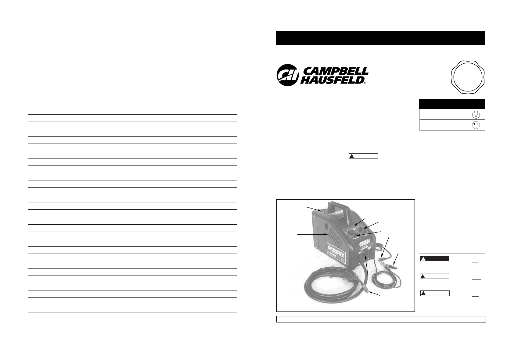
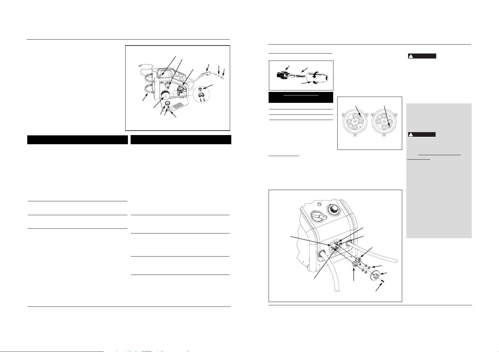
COMPONENTS AND CONTROLS
1. Work Clamp – connects to work
piece.
2. Wire Feed Gun with .035” tip.
3. Power Cord – plug into 115 volt
outlet.
4. Light – illuminates if thermostat has
automatically shut welder off.
5. Infinite Wire Speed Control – turn
clockwise to increase wire speed and
counterclockwise to decrease wire
speed.
6. Off/Heat Selector - Selects welding
power and turns welder on. Four
selections are possible: 1 – 2 – 3 – 4.
7. Polarity Box - For changing to
electrode positive or negative polarity.
8. MIG Gas Hookup
9. Wire Feed Compartment
General Safety
Danger means a
hazard that will
cause death or serious injury if the
warning is ignored.
Warning means a
hazard that could
cause death or serious injury if the
warning is ignored.
Caution means a
hazard that may
cause minor or moderate injury if the
warning is ignored. It also may mean a
hazard that will only cause damage to
property.
R
See page 7 for supply cable
replacement instructions.
Unpacking
Welding accessories are packed inside
the wire feed compartment on the
side of the welder. When unpacking,
inspect carefully for any damage that may
have occurred during transit. Make sure
any loose fittings and screws, etc., are
tightened before putting unit into service.
Report any missing or damaged
items by calling 1-800-746-5641.
CIRCUIT REQUIREMENTS
This equipment
requires a dedicated
115 volt circuit. Refer to the following
chart for correct circuit breaker or fuse
rating. Do not run other appliances, lights
or tools on this circuit while operating
this equipment. Extension cords are not
recommended. Blown fuses and tripped
circuit breakers can result from failure to
comply with this recommendation.
For parts, manuals, product & service information
visit www.chpower.com
© 2004 Campbell Hausfeld/Scott Fetzer
REMINDER: Keep your dated proof of purchase for warranty purposes! Attach it to this manual or file it for safekeeping.
Heat Circuit Breaker or
Selector Slow Blow Fuse
1-2-3 15 amp
4 20 amp
Figure 1 - Welder Components and Controls
3
1
6
4
8
9
5
2
7
Notes
Notes
Notas
44
Wire Feed Arc Welder
Soudeur à l’Arc Alimenté en Fil
Soldadora Por Arco Con Alimentación de Cable
T
I
L
BUILT TO LAST
A
U
Q
Assistance?
Call Us First!
1-800-746-5641
A
Y
A
R
U
S
S
Need
N
C
E
P
R
O
G
R
A
M
!
CAUTION
!
DANGE
!
WARNING
!
CAUTION
Notes
Notes
Notas
43
Models WG2060 and WG2064
Modèles WG2060 et WG2064
Modelos WG2060 y WG2064
2
Wire Feed Arc Welder
General Safety
(Continued)
NOTE: Note means any additional
information pertaining to the product
or its proper usage.
Always keep a fire
extinguisher accessible
while performing arc
welding operations.
Before starting or
servicing any electric arc welder, read
and understand all
instructions. Failure
to follow safety
precautions or
instructions can
cause equipment
damage and/or serious personal
injury or death.
All installation, maintenance, repair
and operation of this equipment
should be performed by qualified
persons only in accordance with
national, state, and local codes.
Improper use of electric
arc welders can cause
electric shock, injury,
and death! Take all
precautions described in
this manual to reduce the possibility of
electric shock.
Verify all components of the arc
welder are clean and in good
condition prior to operating welder.
Be sure insulation on all cables, wire
feed gun and power cord is not
damaged. Always repair or replace
damaged components before
operating the welder. Always keep
welder panels, shields, etc. in place
when operating welder.
Always wear dry, protective
clothing, welding gloves and
insulated footwear when operating
unit.
Always operate welder in a clean,
dry, well ventilated area. Do not
operate welder in humid, wet, rainy
or poorly ventilated areas.
Be sure work piece is properly
supported and grounded prior to
beginning any electric arc welding
operation.
Spread out coiled welding cable
before use to avoid overheating and
damage to insulation.
Never immerse
wire or wire feed
gun in water. If welder becomes wet for
any reason, be absolutely certain it is
completely clean and dry before use!
Always shut equipment off and
unplug power cord prior to moving
the unit.
Always attach the work lead first.
Verify work piece is securely
grounded.
Always shut off electric arc welding
equipment when not in use and cut off
any excess wire from wire feed gun.
Never allow any part of the body to
touch flux-cored wire and ground or
grounded work piece at the same
time.
Awkward welding conditions and
positions can be electrically hazardous.
When crouching, kneeling or at
elevations, be sure to insulate all
conductive parts, wear appropriate
protective clothing and take
precautions to prevent injury from falls.
Never attempt to use this equipment
at current settings or duty cycles higher
than specified on equipment labels.
Never use an electric arc welder to
thaw frozen pipes.
Flying sparks and hot
metal can cause injury.
As welds cool, slag can
be thrown off. Take all
precautions described in
this manual to reduce
the possibility of injury from flying
sparks and hot metal.
Wear ANSI approved face shield or
safety glasses with side shield
protection when chipping or
grinding metal parts.
Wear ear plugs when welding
overhead to prevent spatter or slag
from falling into ears.
R
Electric arc welding
operations produce
intense light and heat
and ultraviolet (UV)
rays. This intense light
and UV rays can cause injury to eyes and
skin. Take all precautions described in
this manual to reduce the possibility of
injury to eyes and skin.
All persons operating this equipment
or in the area while equipment is in
use, must wear protective welding gear
including: welding helmet or shield
with at least shade 10 lens, flame
resistant clothing, leather welding
gloves and full foot protection.
Never look at arc
welding operations
without eye protection as described
above. Never use a shade filter lens
that is cracked, broken, or rated below
number 10. Warn others in the area not
to look at the arc.
Electric arc welding
operations cause sparks
and heat metal to
temperatures that can
cause severe burns! Use
protective gloves and clothing when
performing any metal working
operation. Take all precautions described
in this manual to reduce the possibility
of skin and clothing burns.
Make sure all persons in welding
area are protected from heat, sparks
and ultraviolet rays. Use additional
face shields and flame resistant
barriers as needed.
Never touch work pieces until
completely cooled.
Heat and sparks
produced during
electric arc welding and
other metal working
operations can ignite
flammable and explosive materials!
Take all precautions described in this
manual to reduce the possibility of
flames and explosions.
Remove all flammable materials
within 35 feet (10.7 meters) of
welding arc. If removal is not
possible, tightly cover flammable
materials with fire proof covers.
!
www.chpower.com
WARNING
!
WARNING
!
WARNING
!
DANGE
MANUAL
!
WARNING
!
WARNING
!
WARNING
!
WARNING
Garantía Limitada
Garantía Limitada 5-3-1
1.Duración: El fabricante garantiza que reparará, sin costo alguno, por piezas o mano de obra, la soldadora, pistola de
soldadura o cables que demuestren estar defectuosos, en material o mano de obra, durante el(los) siguiente(s) periodo(s) a
partir de la fecha de compra al por menor original:
Por 5 años: el transformador y rectificador de la soldadora.
Por 3 años: toda la soldadora (salvo las abrazaderas, pistola de soldadura, sujetador de electrodo, cables o accesorios
embalados con la soldadora).
Por 1 año: las abrazaderas de soldadura, pistola MIG, sujetador de electrodo, accesorios y cables de soldadura (como
sea pertinente).
2.¿Quién emite esta garantía? (Garante)
Campbell Hausfeld / A Scott Fetzer Company
100 Production Drive
Harrison, OH 45030
Teléfono: (513)-367-4811
3.¿Quién recibe esta garantía? (Comprador): El comprador original del producto Campbell Hausfeld.
4.¿Qué es lo que cubre esta garantía?: Defectos de material y mano de obra que ocurran dentro del período de duración
de la garantía. Esta garantía se extiende solamente a la soldadora, el transformador y rectificador de la soldadora, pistola
de soldadura o sujetador de electrodo y cables.
5.¿Qué es lo que no cubre esta garantía?:
A.Las garantías implícitas, incluyendo las de comerciabilidad e IDONEIDAD PARA UN FIN PARTICULAR, SE LIMITAN A LA
DURACIÓN DE ESTA GARANTÍA EXPRESA. Luego de este periodo, todos los riesgos de pérdida, por cualquier razón,
corren por cuenta del comprador. Algunos estados no permiten la limitación de la duración de una garantía implícita,
de modo que estas restricciones tal vez no rijan para Ud.
B.CUALQUIER PERDIDA, DAÑO O GASTO INCIDENTAL, INDIRECTO O RESULTANTE QUE PUEDA DERIVARSE DE CUALQUIER
DEFECTO, FALLA O MAL FUNCIONAMIENTO DEL PRODUCTO DE CAMPBELL HAUSFELD. Algunos estados no permiten la
exclusión o limitación de los daños incidentales o derivados, por lo que esta restricción tal vez no rija para Ud.
C.Esta garantía no se aplica a cualquier accesorio incluido en el producto que está sujeto a desgaste por uso; la reparación
o cambio de este accesorio correrá por cuenta del propietario. Estos artículos MIG incluyen, sin sentido limitativo, a las
puntas de contacto, boquillas, revestimientos de pistola, rodillos de mando, limpiador de cable de fieltro. Además, esta
garantía no se extiende a los daños causados por el cambio o mantenimiento fuera de tiempo de cualquiera de las
piezas CONSUMIBLES enumeradas anteriormente.
D.Cualquier falla que resulte de un accidente, mal uso del comprador, negligencia u omisión en operar los productos de
acuerdo a las instrucciones provistas en el manual del propietario suministrado con el producto.
E. Servicio de pre-entrega, es decir, ensamblaje y ajuste.
7.Responsabilidades del garante bajo esta garantía: Reparar o reemplazar, a opción del garante, los productos o
componentes que hayan funcionado mal dentro del período de garantía.
8.Responsabilidades del comprador bajo esta garantía:
A.Entregar o enviar el producto o componente de Campbell Hausfeld al Centro de Servicio Autorizado de Campbell
Hausfeld más cercano. Los costos de envío, si los hubiera, serán por cuenta del comprador.
B.Hacer uso de un cuidado razonable en la operación y mantenimiento de los productos descritos en el manual del
propietario.
9.¿Cuándo efectuará el garante la reparación o reemplazo bajo esta garantía?: La reparación o reemplazo se
programará y efectuará de acuerdo al flujo normal de trabajo en la localidad de servicio y dependiendo de la
disponibilidad de repuestos.
Esta garantía limitada le proporciona a Ud. derechos legales específicos y es probable que Ud. tenga otros derechos, los
cuales varían de un estado a otro.
42 Sp
Soldadora Por Arco Con Alimentación de Cable
General Safety
(Continued)
Do not operate any electric arc
welder in areas where flammable or
explosive vapors may be present.
Take precautions to ensure flying
sparks and heat do not cause flames
in hidden areas, cracks, etc.
Fire hazard! Do not
weld on containers
or pipes that contain or have contained
flammable materials or gaseous or liquid
combustibles.
Arc welding closed
cylinders or containers
such as tanks or drums
can cause explosion if
not properly vented!
Verify that any cylinder or container to
be welded has an adequate ventilation
hole, so that expanding gases can be
released.
Do not breathe fumes
produced by arc
welding operation.
These fumes are
dangerous. If welding
area cannot be adequately ventilated,
be sure to use an air-supplied
respirator.
Keep head and face out of welding
fumes.
Extremely toxic fumes are created
when galvanized or cadmium plated
metals or metals which contain zinc,
mercury or beryllium are heated.
Complete the following precautions
before performing electric arc
welding operations on these metals:
a. Remove coating from base metal.
b. Make sure welding area is well
ventilated.
c. Use an air-supplied respirator.
The electromagnetic field
generated during arc
welding may interfere
with the operation of
various electrical and
electronic devices such as cardiac
pacemakers. Persons using such devices
should consult with their physician prior
equipment, and CGA publication P-1
listed in Safety Standards.
Never use
flammable gasses
with MIG welders. Only inert or nonflammable gasses such as carbon
dioxide, argon, helium or mixtures of
one or more of these gasses are
suitable for MIG welding.
Never lift cylinders
off the ground by
their valves or caps or with chains or
slings.
ADDITIONAL SAFETY STANDARDS
ANSI Standard Z49.1 from American
Welding Society, 550 N.W. Le June Rd.
Miami, FL 33126
Safety and Health Standards
OSHA 29 CFR 1910, from Superintendent
of Documents, U.S. Government Printing
Office, Washington, D.C. 20402
National Electrical Code
NFPA Standard 70, from National Fire
Protection Association, Batterymarch
Park, Quincy, MA 02269
Safe Handling of Compressed Gases
in Cylinders
CGA Pamphlet P-1, from Compressed Gas
Association, 1235 Jefferson Davis
Highway, Suite 501, Arlington, VA 22202
Code for Safety in Welding and
Cutting
CSA Standard W117.2, from Canadian
Standards Association, Standards Sales,
178 Rexdale Boulevard, Rexdale, Ontario,
Canada M9W 1R3
Cutting And Welding Processes
NFPA Standard 51B, from National Fire
Protection Association, Batterymarch
Park, Quincy, MA 02269
Safe Practices For Occupational And
Educational Eye And Face Protection
ANSI Standard Z87.1, from American
National Standards Institute, 1430
Broadway, New York, NY 10018
Refer to Material Safety Data Sheets and
manufacturers instructions for metals,
wire, coatings and cleaners.
R
3
to performing any electric arc welding
operations.
Route wire gun and work cables
together and secure with tape when
possible.
Never wrap arc welder cables around
the body.
Always position wire gun and work
leads on the same side of the body.
Exposure to electromagnetic fields
during welding may have other
health effects which are not known.
Always be sure
welding area is
secure and free of hazards (sparks,
flames, glowing metal or slag) prior to
leaving. Be sure equipment is turned off
and excess wire is cut off. Be sure cables
are loosely coiled and out of the way. Be
sure all metal and slag has cooled.
Cylinders can explode if damaged.
Shielding gas cylinders
contain gas under high
pressure. If damaged, a
cylinder can explode.
Since gas cylinders are
normally part of the
welding process, be
sure to treat them carefully.
Protect compressed gas cylinders
from excessive heat, mechanical
shocks and arcs.
Install and secure cylinders in an
upright position by chaining them
to stationary support or equipment
cylinder rack to prevent falling or
tipping.
Keep cylinders away from any
welding or other electrical circuits.
Never allow a welding electrode to
touch any cylinder.
Use only correct shielding gas
cylinders, regulators, hoses and
fittings designed for the specific
application; maintain all parts
properly.
Turn face away from valve outlet
when opening cylinder valve.
Keep protective cap in place over
valve except when cylinder is in use
or connected for use.
Read and follow instructions on
compressed gas cylinders, associated
R
Models WG2060 and WG2064
www.chpower.com
!
WARNING
!
WARNING
!
WARNING
!
WARNING
!
WARNING
!
DANGE
!
DANGE
!
WARNING
41 Sp
Corriente alterna o CA – corriente
eléctrica que invierte periódicamente la
dirección. La corriente de ciclo de
sesenta viaja en ambas direcciones,
sesenta veces por segundo.
Longitud del arco - la distancia entre el
extremo del electrodo y la punta donde el
arco hace contacto con la superficie de
trabajo.
Metal de base – el material que va a ser
soldado.
Unión plana – una unión entre las dos
partes alineadas aproximadamente en el
mismo plano.
Cráter – charco de metal fundido o
bolsillo que se forma cuando el arco se
pone en contacto con el metal de base.
Corriente continua o CC – corriente
eléctrica que circula solamente en una
dirección. La polaridad (+ o -) determina
en qué dirección está circulando la
corriente.
Polaridad inversa de CC – ocurre cuando
el sujetador del electrodo está
conectado al polo positivo de la
máquina soldadora. La polaridad
inversa dirige más calor para fundir al
electrodo que a la pieza de trabajo. Se
utiliza en materiales más delgados.
Polaridad directa de CC - ocurre cuando
el sujetador del electrodo está
conectado al polo negativo de la
máquina soldadora. Con la polaridad
directa se dirige más calor hacia la pieza
de trabajo para una mejor penetración
en materiales más gruesos.
Electrodo – un alambre de metal
revestido que tiene aproximadamente la
misma composición que el material que
va a ser soldado.
Soldadura en ángulo –
aproximadamente un triángulo en
sección transversal, que une dos
superficies con ángulos rectos en cada
uno en una unión de solapa, en T o de
ángulo.
Glosario de Términos de Soldadura
Modelos WG2060 y WG2064
Fundente - un material, que al
calentarse, emite un gas que cubre el
área donde va a soldar. Este gas protege
los metales que va a soldar contra las
impurezas presentes en el aire.
Soldadura por arco de núcleo fundente
(FCAW) – también llamado Sin gas, es
un proceso de soldadura utilizado con
una máquina soldadora de alimentación
de cable. El cable de soldadura es
tubular que contiene dentro material
fundente como protección.
Soldadura por arco de metal de gas
(GMAW) – también llamado MIG, es un
proceso de soldadura utilizado con una
máquina soldadora de alimentación de
cable. El cable es sólido y se utiliza un gas
inerte como protección.
Soldadura por arco de tungsteno de gas
(GTAW) – también llamado TIG, es un
proceso de soldadura utilizado con un
equipo soldador con un generador de
alta frecuencia. El arco se crea entre un
electrodo de tungsteno no consumible y
la pieza de trabajo. El metal de relleno
se puede o no utilizar.
Unión de solapa – una unión entre dos
partes superpuestas en planos paralelos.
Voltaje de circuito abierto (OCV) – el
voltaje entre el electrodo y la
abrazadera de trabajo de la máquina
soldadora, cuando no circula corriente
(no suelda). El OCV determina cuán
rápido se golpea el arco.
Superposición – ocurre cuando el
amperaje está configurado demasiado
bajo. En este caso, el metal fundido cae
del electrodo sin realmente fundir el
metal de base.
Porosidad – bolsillos o cavidades de
gases, formados durante la
solidificación. Debilitan la soldadura.
Penetración – la profundidad en la pieza
de trabajo que ha sido afectada por el
calor por el arco durante el proceso de
soldadura. Una buena soldadura logra
100% de penetración, lo cual significa
que todo el espesor de la pieza de
trabajo ha sido calentado y
resolidificado. El área afectada por el
calor se debe ver fácilmente al lado
opuesto de la soldadura.
Soldadura por arco de metal blindado
(SMAW) – también llamada Soldadura
con Varilla, es un proceso de soldadura
que utiliza un electrodo consumible para
sostener el arco. El blindaje se obtiene
por la fundición del revestimiento del
fundente en el electrodo.
Escoria – una capa de hollín de
fundente que protege la soldadura de
los óxidos y otros contaminantes
mientras la soldadura se está
solidificando (enfriando). La escoria
debe retirarse luego de que la
soldadura haya enfriado.
Salpicadura – partículas de metal que
saltan de la soldadura, que se enfrían y
endurecen en la superficie de trabajo.
La salpicadura se puede disminuir
aplicando un aerosol resistente a
salpicaduras en la pieza de trabajo antes
de soldar.
Soldadura por puntos – soldadura hecha
para sostener las partes en la alineación
correcta hasta realizar las soldaduras
finales.
Angulo de propagación – el ángulo del
electrodo en la línea de soldadura.
Varía entre 5° y 45° dependiendo de las
condiciones de soldadura.
Unión en T – realizada al colocar el
borde de una pieza o metal en la
superficie de la otra pieza a
aproximadamente un ángulo de 90°.
2. Remove the spool quick lock by
pushing in and rotating 1/4 turn
counterclockwise. Then remove
knob, spring and spool spacer.
3. Flip tensioning screw down on drive
mechanism. This allows initial
feeding of wire into gun liner by
hand.
4. Install wire spool onto spindle so
wire can come off spool on the end
closest to the wire feed guide tube.
Do not cut the wire loose yet.
Install spool spacer, spring and quick
lock knob by pushing in and turning
knob 1/4 rotation clockwise.
5. Hold wire and cut the wire end from
spool. Do not allow wire to
unravel. Be sure end of wire is
straight and free of burrs.
6. Feed wire through wire feed guide
tube, over the groove in drive roller
and into gun liner. Flip tensioning
screw up and adjust tension by rotating
4
Wire Feed Arc Welder
Installation
LOCATION
Selecting the proper location can
significantly increase performance,
reliability and life of the arc welder.
For best results locate welder in a
clean and dry environment. Dust
and dirt in the welder retain
moisture and increase wear of
moving parts.
Place welder in an area with at least
twelve inches (305 mm) of ventilation
space at both the front and rear of
unit. Keep all obstructions out of this
ventilation space.
Store welding wire in a clean, dry
location with low humidity to
prevent oxidation.
Use a properly grounded receptacle
for the welder and ensure welder is
the only load on power supply
circuit. Refer to chart on page 1 for
correct circuit capacity.
Use of an extension cord is not
recommended for electric arc welding
machines. Voltage drop in the
extension cord may significantly
degrade performance of the welder.
Assembly
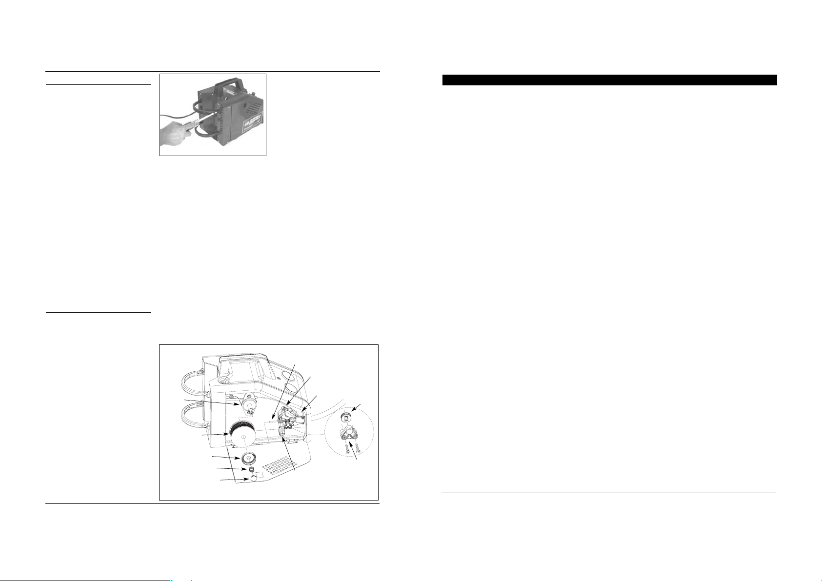
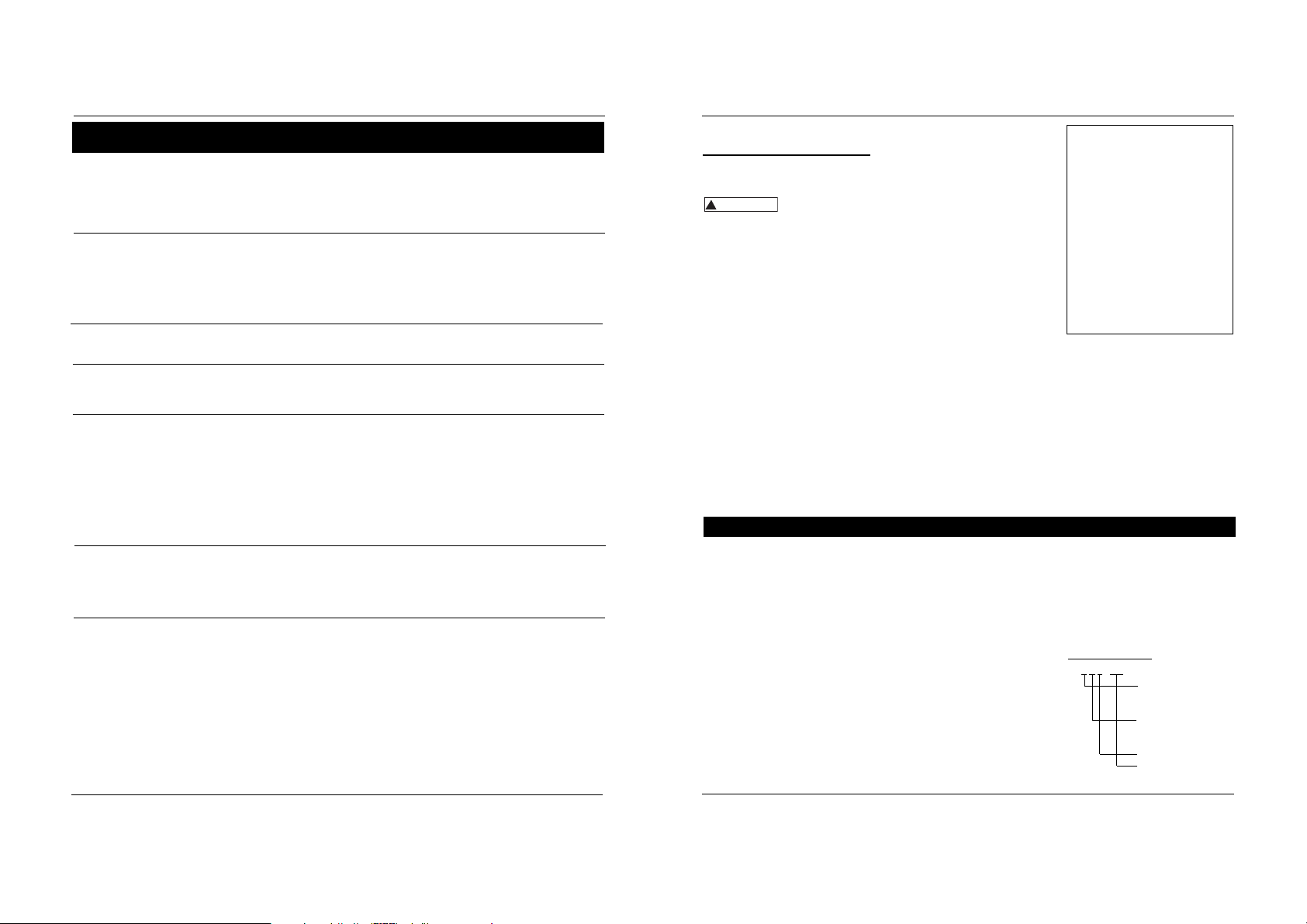
BOTTLE RETAINER ASSEMBLY
Attach bottle retainer to welder as
shown (Fig. 2).
WIRE INSTALLATION
NOTE: Before installing welding wire,
be sure:
a. Diameter of welding wire matches
groove in drive roller on wire feed
mechanism (See Fig. 3). The drive
roller is marked with metric sizes:
.6mm = .024”, .8 - .9mm = .030 –
.035”
b. Wire matches contact tip in end of
gun. (See Fig. 4).
A mismatch on any item could cause the
wire to slip and bind.
NOTE: Always maintain control of loose
end of welding wire to prevent
unspooling.
1. Verify unit is off and open door
panel to expose wire feed
mechanism.
tensioning screw knob. Do not over
tighten.
7. Remove nozzle by turning counterclockwise, then unscrew contact tip
from end of welding torch (See
Figure 4). Plug welder into a proper
power supply receptacle.
8. Turn on welder and set wire speed
rate to 10. Activate gun trigger until
wire feeds out past the torch end.
Turn welder off.
9. Carefully slip contact tip over wire
and screw tip into torch end. Install
nozzle by turning clockwise (See
Figure 4). Cut wire off approximately
1/4 inch from nozzle end.
DUTY CYCLE / THERMOSTATIC
PROTECTION
Welder duty cycle is the percentage of
actual weld time that can occur in a ten
minute interval. For example, at a 20%
duty cycle, actual welding can occur for
two minutes, then the welder must cool
for eight minutes.
Internal components of this welder are
protected from overheating with an
automatic thermal switch. A yellow
lamp is illuminated on the front
panel if the duty cycle is exceeded.
Welding operations may continue when
the yellow lamp is no longer illuminated.
Figure 2 - Bottle Retainer Assembly
www.chpower.com
Spindle
Welding wire
Tensioner ring
Tension spring
Retainer
Tensioner knob
Guide tube
Tensioner arm
Drive deck
Roller
support
Drive
roller
Figure 3 - Weld Wire Routing
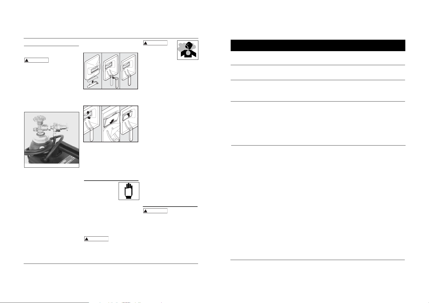
2. Remove cover screw and polarity
cover.
3. Remove four nuts from polarity
studs.
4. Pull out polarity bus bar and rotate
it 90°. Reinsert aligning groove with
the correct rib in polarity box.
Upper right rib marks the MIG
position; lower right rib marks the
Flux position. (See Figure 4c.)
5. Reinstall four nuts and tighten
securely.
6. Reinstall polarity cover and cover
screw.
7. Make sure arrow on polarity cover
points to desired setting.
Assembly (Continued)
POLARITY
MIG welding wire requires electrode
positive electrical polarity. Flux welding
wire requires electrode negative
electrical polarity. The welder is factory
set for flux welding wire.
To Change Polarity
(See Figure 4b)
NOTE: The arrow on the Polarity Cover
points to the current polarity setting.
TOOLS NEEDED: Phillips screwdriver
and 10mm socket wrench.
1. Unplug power cord from socket.
40 Sp
1 Ensamble del soplete y la manguera
(MIG, 2,44 m, WG2060) WC403660AV 1
Ensamble del soplete y la manguera
(MIG, 3,05 m, WG2064) WC404100AV 1
2 Punta de contacto - 0,035” (0,9 mm) WT501400AV 1
Punta de contacto opcional – 0,024”
(0,6 mm) Paq. 4 WT501200AJ †
Punta de contacto opcional – 0,030”
(0,8 mm) Paq. 4 WT501300AJ †
Punta de contacto opcional – 0,035”
(0,9 mm) Paq. 4 WT501400AJ †
3 Boquilla WT502100AV 1
4 Portabobinas WC500805AV 1
5 Ensamble de la placa de conducción WC500800AJ 1
6 Vástago y rejilla WC707018AV 1
7 Retén de la bobina WC707024AV 1
8 Resorte del retén de la bobina WC707026AV 1
9 Anillo del retén de la bobina WC707023AV 1
10 Alambre de soldar con fundente – 0,030”
(0,8 mm) Bobina de 2 lb. (0,9 kg) (E71T-GS) WE200001AV †
Alambre de soldar con fundente – 0,030”
(0,8 mm) Bobina de 10 lb. (4,54 kg) (E71T-GS WE201000AV †
Alambre de soldar con fundente – 0,035”
(0,9 mm) Bobina de 2 lb. (0,9 kg) (E71T-GS) WE200501AV †
Alambre de soldar con fundente – 0,035”
(0,9 mm) Bobina de 10 lb. (4,54 kg) (E71T-GS) WE201500AV †
Alambre de soldar MIG – 0,024”
(0,6 mm) Bobina de 2 lb (0,9 kg) (ER70S6) WE300001AV †
Alambre de soldar MIG – 0,024”
(0,6 mm) Bobina de 11 lb. (5 kg) (ER70S6) WE301500AV †
No de No De
Ref. Descripción Componente Cant
Modelos WG2060 y WG2064
Alambre de soldar MIG – 0,030” (0,8 mm)
Bobina de 2 lb. (0,9 kg) (ER70S6) WE 300501AV †
Alambre de soldar MIG – 0,030” (0,8 mm)
Bobina de 11 lb. (5 kg) (ER70S6) WE 302000AV †
Alambre de soldar MIG – 0,035” (0,9 mm)
Bobina de 2 lb. (0,9 kg) (ER70S6) WE 301001AV †
Alambre de soldar MIG – 0,035” (0,9 mm)
Bobina de 11 lb. (5 kg) (ER70S6) WE 302500AV †
Alambre de soldar MIG – 0,030” (0,8 mm)
1 lb (0,45 kg) de aluminio (ER5356) WE 303001AV †
11 Retén del recipiente con 4 tornillos WC302600AJ 1
12 Conexión dentada de la manguera
(externa) WC403900AV 1
Accesorio de conexión rápida
(interna) WC403901AV 1
13 Manguera de gas – 22” (56 cm) WC403902AV 1
14 Abrazadera de la manguera WC403903AV 2
15 Regulador (WG2060) WC803500AV 1
Regulador (WG2064) WC803600AV 1
16 Máscara de mano
(no se incluyen lentes) WC801700AV 1
17 Lentes oscuros
(para máscara de mano) WC801100AV 1
18 Martillo/cepillo cincelador WC803400AV 1
19 Etiqueta adhesiva de seguridad DK688509AV 1
20 Juego de la barra de polaridad WC403128AV 1
21 Pinza de tierra (WG2060) WC100300AV 1
Pinza de tierra (WG2064) WC100600AV 1
22 Guantes para soldar (sólo WG2064) WT200501AV 1
No se muestra
† Accesorio opcional
No de No De
Ref. Descripción Componente Cant
Soldadora Por Arco Con Alimentación de Cable
3
4
1
8
9
2
11
10
7
12
6
5
Figura 14 - Piezas de Repuesto
Para Ordenar Repuestos o
Asistencia Técnica, Sírvase Llamar
al Distribuidor Más Cercano a Su
Domicilio
Dirija toda la correspondencia a:
Campbell Hausfeld
Attn: Customer Service
100 Mundy Memorial Drive
Mt. Juliet, TN 37122 U.S.A.
Sírvase suministrarnos la siguiente información:
- Número del modelo
- Número de Serie (de haberlo)
- Descripción y número del repuesto según la
lista de repuestos
Shielding Gas Preparation
Improper handling
and maintenance of
compressed gas cylinders and regulators
can result in serious injury or death!
Always secure gas cylinders to tank
bracket kit, a wall or other fixed support
to prevent cylinder from falling over.
Read, understand and follow all
compressed gas and equipment
warnings in the safety instructions.
NOTE: Shielding gas is not required if
flux-core welding wire is used.
GAS TYPES
There are 3 types of gas generally used
for gas metal arc welding; 100% argon,
a mixture of 75% argon and 25%
carbon dioxide (C25) or 100% carbon
dioxide.
Use ONLY the type
of gas recommended
for your welder. Use ONLY an inert, nonflammable type of gas. Failure to do so
will result in a very hazardous situation.
NOTE: 100% carbon dioxide is not
recommended due to unsatisfactory
weld beads.
The 75/25 mixture is recommended for
general steel welding. For aluminum
welding, use 100% argon. Cylinders of
either type gas may be obtained at your
local welding supply outlet. Secure
cylinder in place on your welding
machine or other support to prevent the
cylinder from falling over.
Obtaining Correct Gas Type. The gas
used in any welding application for your
welder must be an INERT, NONFLAMMABLE TYPE. You can get the type
of gas needed from a nearby welding
gas distributor (often found in the
yellow pages under “Welders” or
‘Welding Equipment”).
REGULATOR
An adjustable regulator without gauges
is supplied with the WG2060. The
regulator supplied with the WG2064
includes two gauges. The regulator
provides a constant shielding gas pressure
and flow rate during the welding process.
Each regulator is designed to be used
with a specific gas or mixture of gases.
The argon and argon mixture use the
same thread type. The 100% carbon
dioxide uses a different thread type. An
adapter is available at your local welding
gas supplier to change between the two.
R
5
Models WG2060 and WG2064
www.chpower.com
Contact Tip Markings
Mark Wire Size
0.6 mm .024"
0.8 mm .030”
0.9 mm .035”
Torch Diffuser
Contact Tip
Nozzle
Figure 4 - Torch Nozzle
Figure 4b
Polarity box
Flux rib
Polarity bus bar
Nuts
Cover screw
Polarity
cover
Groove
Polarity studs
MIG rib
Figure 4c
MIG position
Flux position
Upper right—
MIG rib
Lower right—
Flux rib
!
DANGER
!
DANGE
39 Sp
Table de Detección y Solución de Problemas - Soldadura
Síntoma Causas Posibles Medida Correctiva
Reborde es muy
delgado en algunos
sitios
Reborde es muy
grueso en algunos
sitios
Los bordes de la
soldadura están
disparejos
La soldadura no
penetra el metal que
desea soldar
El electrodo salpica y
se pega
1. La velocidad de desplazamiento varia o
es rápida
2. El nivel del amperaje es muy bajo
1. La velocidad de desplazamiento varia o
es muy lenta
2. El nivel del amperaje es muy alto
1. La velocidad de desplazamiento es
muy rápida
2. La velocidad de alimentación es muy
rápida
3. El nivel del amperaje es muy alto
1. La velocidad de desplazamiento no es
consistente
2. El nivel de energía es muy bajo
3. Se terminó el gas o el nivel de gas es
muy bajo
4. Está usando el gas incorrecto
(aluminio)
5. El cordón de extensión es muy largo
6. (Aluminio) Posiblemente se están
formando residuos de óxido en la
superficie
1. El alambre está húmedo
2. La velocidad del alambre está muy
rápida
3. Está utilizando el alambre inadecuado
4. Se terminó el gas o el nivel de gas es
muy bajo
1. Debe reducirla y mantenerla constante
2. Debe aumentarlo
1. Debe aumentarla y mantenerla constante
2. Debe bajarlo
1. Debe reducirla
2. Debe aumentarla
3. Debe bajarlo
1. Disminuya la velocidad y manténgala constante
2. Aumente el nivel de energía de suministro
3. Use gas, para soldar con gases inertes (MIG) o llene la boqtella
4. Use sólo 100% Argón
5. Nunca use cordones de extensión de más de 6,10 m (20 pies)
6. Limpie bien la superficie con un cepillo de acero inoxidable
sólamente
1. Use un alambre seco y siempre debe almacenarlo e un sitio
seco
2. Reduzca la velocidad del alambre
3. Use alambre de fundente revestido cuando no esté utilizando
gases
4. Use gas, para soldar con gases inertes (MIG) o llene la boqtella
Modelos WG2060 y WG2064
2. To attach the handle, place shield on
a flat surface and press handle into
place – see Figure 6.
3. Insert filter lens exactly as shown in
Figure 7.
NOTE: If you have never welded
before or have little experience, a
full face helmet is recommended.
Both hands are needed to stabilize
and control the angle and arc
length of the torch.
Operation
1. Be sure to read,
understand and comply
with all precautions in
the General Safety
Information section. Be
sure to read entire "Welding
Guidelines" section before using this
equipment.
2. Turn welder off.
3. Verify surfaces of metals to be joined
are free from dirt, rust, paint, oil,
scale or other contaminants. These
contaminants make welding difficult
and cause poor welds.
All persons
operating this
equipment or in the area while
equipment is in use must wear
protective welding gear including: eye
protection with proper shade, flame
resistant clothing, leather welding
gloves and full foot protection.
Assembly (Continued)
HOSE AND REGULATOR HOOKUP
PROCEDURE
Cylinder gas is under high pressure.
Point cylinder outlet away from
yourself and any bystanders before
opening.
1. With cylinder securely installed, stand
on side of cylinder opposite cylinder
outlet then remove cylinder cap and
open valve slightly by turning
counterclockwise. When gas is
emitted from cylinder, close valve by
turning clockwise. This will blow out
dust or dirt that may have
accumulated around valve seat.
2. Install regulator onto cylinder valve.
Tighten stem nut securely to gas
valve.
3. Install one end of gas hose to fitting
on the top of welder and other end of
hose to fitting on regulator using hose
clamps on each connection. Make sure
gas hose is not kinked or twisted.
4. While standing opposite cylinder
outlet, slowly open cylinder valve.
Inspect for leaks in the connections.
5. Pull trigger on gun to allow gas to
flow. Adjust gas regulator to
maximum flow by rotating clockwise.
Release trigger.
6. Remember to close gas cylinder valve
when finished welding.
Handshield Assembly
1. Cut detachable handle away from
shield. Trim the excess plastic to
remove sharp edges – see Figure 6.
6
Wire Feed Arc Welder
If heating, welding or
cutting galvanized, zinc
plated, lead, or cadmium
plated materials, refer to
the General Safety
Information Section for instructions.
Extremely toxic fumes are created when
these metals are heated.
4. Connect work clamp to work piece or
workbench (if metal). Make sure
contact is secure. Avoid surfaces with
paint, varnish, corrosion or nonmetallic materials.
5. Rotate Wire Speed Control to setting
number 5 to start, then adjust as
needed after test.
6. Plug power cord into a proper
voltage receptacle with proper circuit
capacity (see circuit requirements on
front page).
7. Switch welder on to desired heat
setting per decal inside wire feed
compartment.
NOTE: These settings are general
guidelines only. Heat setting may vary
according to welding conditions and
materials.
8. Verify wire is extended 1/4” from
contact tip. If not, squeeze trigger to
feed additional wire, release trigger,
turn welder off, and cut wire to
proper length. Then, switch back on
to desired heat setting.
9. Position wire feed gun near work
piece, lower welding helmet by
nodding head or positioning the hand
shield, and squeeze gun trigger. Adjust
heat setting and wire speed as needed.
10. When finished welding, turn welder
off and store properly.
Maintenance
Disconnect power
supply and turn
machine off before inspecting or
servicing any components. Keep wire
compartment cover closed at all times
unless wire needs to be changed.
BEFORE EVERY USE:
1. Check condition of weld cables and
immediately repair or replace any
cables with damaged insulation.
2. Check condition of power cord and
immediately repair or replace any
cord if damaged.
!
www.chpower.com
Figure 5 - Hose and Regulator Hookup
Figure 6
Figure 7
WARNING
!
WARNING
!
WARNING
MANUAL
!
WARNING
WIRE TYPE AND SIZE
The correct choice of wire type
involves a variety of factors, such as
welding position, work piece material
type, thickness, and condition of
surface to be welded. The American
Welding Society, AWS, has set up
certain requirements for each type of
wire.
FLUX-CORED WIRE
E - 7 0 T - GS
Weld strength, times
10,000 pounds per
square inch
Welding positions (0
for flat or horizontal,
1 for any position)
Tubular flux-cored wire
Flux type
38 Sp
Soldadora Por Arco Con Alimentación de Cable
Table de Detección y Solución de Problemas - Soldadora
Síntoma Causas Posibles Medida Correctiva
1. Excedio el ciclo de trabajo
2. La pinza está mal conectada
3. El interruptor está dañado
4. El cortacircuito se activó o el
fusible está quemado
1. La boquilla de la pistola es de
un tamaño incorrecto
2. El forro de la pistola está
obstruído o dañado
3. La boquilla de la pistola está
obstruída o dañada
4. El rodillo está desgastado
5. No hay suficiente tensión
Hay escoria dentro de la boquilla
pistola
1. Hay mal contacto
2. Está usando un cordón de
extensión demasiado largo
1. El alambre está atascado
2. Se terminó el alambre
3. No hay suficiente tensión
4. El forro del alambre está
dañado
1. Espere que la soldadora se enfríe, cuando el bombillo se
apague
2. Cerciórese de que las conexiones estén bien hechas y de que la
superficie esté limpia
3. Reemplace el interruptor
4. Reduzca la carga del circuito, active el cortacircuito o
reemplace el fusible
1. Use una boquilla adecuada
2. Límpielo o reemplácelo
3. Límpiela o reemplácela
4. Reemplácelo
5. Apriete el tornillo
Cerciórese de que todas las conexiones esten bien aseguradas, y
de que la superfice este limpia.
1. Cercórese de que todas las conexiones estén bien aseguradas y
que la superficie de contacto esté limpia
2. Nunca use cordones de extensión de más de 6,10 m (20 pies)
1. Recargue el alambre (1-5 acero dulce; 5-10 aluminio)
2. Reemplace el carrete
3. Apriete los tornillos si el cable se desliza
4. Reemplace el forro
No funciona
El alambre se enrolla en la
bobina
Ocurre un arco entre la
boquilla de la pistola y la
superficie de trabajo
La pinza de trabajo y/o el
cable se calientan
El alambre no circula
(Aluminio) el alambre se
quema en el extremo de la
boquillla o (Aluminio) se
forman burbujas en el
metal o se funde
completamente
La soldadura se ampolla y
salpica
5. El fusible está quemado
(WG3060)
6. El alambre está desconectado
internamente
7. La boquilla de contacto está
obstruida
1. La velocidad de alimentación es
muy lenta
2. La velocidad de desplazamiento
es muy baja o la energía es muy
alta
1. Ajustes de velocidad del cable
2. Punta de contacto demasiado
grande
3. Polaridad conectada
incorrectamente
4. Resbala el portabobinas
5. Tanque de gas vacío
5. Reemplace el fusible en el tablero de control, dentro de la
soldadora (3,15 amp de accón retardada)
6. Llame al 1-800-746-5641 (en EUA) para recibir asistenciia
7. Reemplace la boquilla de contacto
1. Use velocidades entre 7 - 10
2. Aumente la velocidad de desplazamiento o disminuya la
energía
1. Ajuste el valor correcto
2. Remplace la punta de contacto
3. Invierta la polaridad
4. Aumente la tensión
5. Remplace el tanque de gas
7
Welding Guidelines
Models WG2060 and WG2064
Supply Cable Replacement
1. Verify that welder is OFF and
power cord disconnected.
2. Remove welder side panel to
expose switches.
3. Disconnect the black power cord
wire connected to the switch
and the white cord wire from
the transformer windings.
4. Disconnect the green power
cord wire connected to welder
base.
5. Loosen the cord strain relief
screw(s) and pull cord out of
strain relief and wire post.
6. Install new cord in reverse order.
General
This welding machine can utilize the Flux
Cored Arc Welding (FCAW) process or
the Gas Metal Arc Welding (GMAW)
process. The weld must be protected
(shielded) from contaminants in the air
while it is molten. The FCAW process uses
a tubular wire with a flux material inside.
The flux creates a shielding gas when
melted. The GMAW process uses inert
gas to shield the weld while molten.
When current is produced by a
transformer (welding machine) and flows
through the circuit to the weld wire, an
arc is formed between the end of the
weld wire and the work piece. This arc
melts the wire and the work piece. The
melted metal of the weld wire flows into
the molten crater and forms a bond with
the work piece as shown (Figure 8).
Arc Welding Basics
Five basic techniques affect weld quality.
These are: wire selection, heat setting,
weld angle, wire speed, and travel
speed. An understanding of these
techniques is necessary for effective
welds.
HEAT SETTING
The correct heat involves the adjustment
of the welding machine to the required
setting. Heat or voltage is regulated by a
switch on the welder. The heat setting
used depends on the size (diameter) and
type of wire, position of the weld, and
the thickness of the work piece. Consult
specifications listed on the welder. It is
suggested that the welder practice with
scrap metal to adjust settings, and
compare welds with Figure 10.
www.chpower.com
Maintenance
(Continued)
3. Inspect the condition of the gun tip
and nozzle. Remove any weld slag.
Replace gun tip or nozzle if damaged.
Do not operate this
welding machine
with cracked or missing insulation on
welding cables, wire feed gun or power
cord.
EVERY 3 MONTHS:
1. Replace any unreadable safety labels
on the welder.
2. Use compressed air to blow all dust
and lint from ventilation openings.
3. Clean wire groove on drive roller.
Remove wire from feed mechanism,
remove screws from drive roller
housing. Use a small wire brush to
clean drive roll. Replace if worn or
damaged
Consumable and Wear Parts
The following parts require routine
maintenance:
• Wire feed drive roller
• Gun liner - replace if worn
• Nozzle/contact tips
• Wire - This welder will accept either 4”
or 8” diameter spools. Flux-Cored
welding wire is susceptible to
moisture and oxidizes over time, so it
is important to select a spool size that
will be used within approximately 6
months. For mild steel welding, AWS
ER70S6 solid wire or AWS E71T-GS
Flux-Cored wire is recommended.
CHANGING WIRE SIZES
This welder is setup for .035 (.9mm)
wire. If a different wire size is used, the
wire feed drive roller and contact tip
may need changing. There are two
grooves in the drive roller. The small
groove is for .024 (.6mm) wire and the
other is for .030-.035 (.8-.9mm) wire.
Remove the roller cover and flip the
drive roller to choose the correct
groove (See parts breakdown). The
contact tip should also match the wire
diameter used. The tip diameter is
marked on the contact tip in inches or
millimeters.
!
WARNING
 Loading...