


Manual Instrucciones
Garantía Limitada
1.DURACIÓN: Desde la fecha de compra por parte del comprador original, según se detalla: Campbell Hausfeld (Trabajo estándar y sin especificar) – 1 (un) año, (Trabajo pesado) – 2 (dos) años, (Trabajo extremo) – 3 (tres) años; IronForce de Campbell Hausfeld – 1 (un) año; Farmhand – 3 (tres) años; Maxus – 5 (cinco) años.
2.QUIEN OTORGA ESTA GARANTIA (EL GARANTE: Campbell Hausfeld / The Scott Fetzer Company 100 Production Drive, Harrison, Ohio 45030 Teléfono: (800) 543-6400
3.QUIEN RECIBE ESTA GARANTIA (EL COMPRADOR): El comprador original (que no sea un revendedor) del producto Campbell Hausfeld.
4.PRODUCTOS CUBIERTOS POR ESTA GARANTIA: Cualquier clavadora, grapadora, herramienta neumática, pistola pulverizadora, inflador o accesorio neumático suministrado o fabricado por el Garante.
5.COBERTURA DE LA GARANTIA: Los defectos substanciales de material y fabricación que ocurran dentro del período de validez de la garantía.
6.LO QUE NO ESTA CUBIERTO POR ESTA GARANTIA:
A.Las garantías implícitas, incluyendo aquellas de comercialidad E IDONEIDAD PARA FINES PARTICULARES, ESTAN LIMITADOS A LO ESPECIFICADO EN EL PARRAFO DE DURACION. Si este producto es empleado para uso comercial, industrial o para renta, la garantía será aplicable por noventa (90) días a partir de la fecha de compra. En algunos estados no se permiten limitaciones a la duración de las garantías implícitas, por lo tanto, en tales casos esta limitación no es aplicable.
B.CUALQUIER PERDIDA DAÑO INCIDENTAL, INDIRECTO O CONSECUENTE QUE PUEDA RESULTAR DE UN DEFECTO, FALLA O MALFUNCIONAMIENTO DEL PRODUCTO CAMPBELL HAUSFELD. En algunos estados no se permite la exclusión o limitación de daños incidentales o consecuentes, por lo tanto, en tales casos esta limitación o exclusión no es aplicable
C.Cualquier falla que resulte de un accidente, abuso, negligencia o incumplimiento de las instrucciones de funcionamiento y uso indicadas en el (los) manual(es) que se adjunta(n) al producto. Dichos accidentes, abusos por parte del comprador, o falta de operar el producto siguiendo las instrucciones del manual de instrucciones suministrado también debe incluir la desconexión o modificación de los instrumentos de seguridad. Si dichos instrumentos de seguridad son desconectados, la garantía quedaría cancelada.
D.Los ajustes normales explicados en el(los) manual(es) suministrado(s) con el producto.
E.Artículos o servicios normalmente requeridos para el mantenimiento del producto, tales como: anillos en O, resortes, amortiguadores, defensas, hojas de impulsor, fusibles, baterías, empaques, almohadillas o sellos, boquillas de fluído, agujas, boquillas para rociar arena, lubricantes, mangueras de material, elementos filtrantes, álabes de motores, abrasivos, hojillas, discos para cortar, cinceles, retenes para cinceles, cortadores, collarines, mandriles, mordazas para remachadoras, brocas para desarmadores, almohadillas para lijar, soportes de almohadillas, mecanismo de impacto o cualquier otro artículo desgastable que no se haya enumerado específicamente. Estos artículos sólo estarán cubiertos bajo esta garantía por noventa (90) días a partir de la fecha de compra original. Los artículos subrayados sólo están garantizados por defectos de material o fabricación.
F.Defectos estéticos que no interfieran con la función del producto
7.RESPONSABILIDADES DEL GARANTE BAJO ESTA GARANTIA: Reparar o reemplazar, como lo decida el Garante, los productos o componentes que estén defectuosos, se hayan dañado o hayan dejado de funcionar adecuadamente, durante el período de validez de la garantía
8.RESPONSABILIDADES DEL COMPRADOR BAJO ESTA GARANTIA:
A.Suministrar prueba fechada de compra y la historia de mantenimiento del producto.
B.Entregar o enviar el producto o componente Campbell Hausfeld al Centro de Servicio autorizado Campbell Hausfeld más cercano. Los gastos de flete, de haberlos, deben ser pagados por el comprador.
C.Seguir las instrucciones sobre operación y mantenimiento del producto, tal como se indica(n) en el (los) manual(es) del propietario
9.CUANDO EFECTUARA EL GARANTE LA REPARACION O REEMPLAZO CUBIERTO BAJO ESTA GARANTIA: La reparación o reemplazo dependerá del flujo normal de trabajo del centro de servicio y de la disponibilidad de repuestos.
Esta garantía limitada es válida sólo en los EE.UU., Canadá y México y otorga derechos legales específicos. Usted también puede tener otros derechos que varían de un Estado a otro. o de un país a otro.
24 Sp
See Warranty on page 8 for important information about commercial use of this product.
Operating Instructions |
Model SN268K00 |
|
|
Please read and save these instructions. Read carefully before attempting to assemble, install, operate or maintain the product described. Protect yourself and others by observing all safety information. Failure to comply with instructions could result in personal injury, death and/or property damage! Retain instructions for future reference.
Finishing
Stapler
BUILT TO LAST
Table of Contents
General Safety . . . . . . . . . . . . 1-3
Specifications . . . . . . . . . . . . . . 2
Operating The Tool . . . . . . . . 3-5
Troubleshooting . . . . . . . . . . . . 6
Warranty . . . . . . . . . . . . . . . . . . 8
Description
This stapler is designed for cabinetry, casebacks, decorative trim and crafts. Features include: convenient bottom loading magazine which holds up to 100 staples, sequential trip safety mechanism and a narrow nose for accurate fastener placement in tight applications.
General Safety
Information
CALIFORNIA PROPOSITION 65
You can create dust when you cut, sand, drill or grind materials such as wood,
paint, metal, concrete, cement, or other masonry. This dust often contains chemicals known to cause cancer, birth defects, or other reproductive harm.
Wear protective gear.
Excessive exposure
to vibration, working in awkward positions and repetitive work motions can cause injury to hands and arms. Stop using any tool if discomfort, numbness, tingling or pain occur and consult a physician.
This manual contains safety, operational and maintenance information. Contact your Campbell Hausfeld representative if you have any questions.
OPERATOR’S RESPONSIBILITY:
The tool operator is responsible for:
•Reading and understanding tool labels and manual.
•Selecting an appropriate tool actuation system, taking into consideration the work application for which the tool is used.
•The safe use of the tool.
•Ensuring that the tool is used only when the
operator and all other personnel in the work
area are wearing ANSI
Z87 eye protection equipment, and when required, other appropriate protection equipment such as head, hearing and foot protection equipment. Serious eye or permanent hearing loss could result.
•Assuring that the tool is kept in safe working order as described in this manual.
EMPLOYER’S RESPONSIBILITY:
•Selecting an appropriate tool actuation system, taking into consideration the work application for which the tool is used.
•Ensuring that this manual is available to operators and personnel performing maintenance.
•The safe use of the tool.
•Enforcing that the tool is used only when the
operator and all other personnel in the work
area are wearing ANSI
Z87 eye protection equipment, and when required, other appropriate
Model SN268K
Locate model and date code on tool magazine and cap and record below:
Model No. ________________________
Date Code ________________
Retain these numbers for future reference.
protection equipment such as head, hearing and foot protection equipment. Serious eye or permanent hearing loss could result.
•Assuring that the tool is kept in safe working order as described in this manual.
•Assuring the proper maintenance of all tools in employer’s possession.
•Ensuring that tools which require repair are not further used before repair. Tags and physical segregation are recommended means of control.
REMINDER: Keep your dated proof of purchase for warranty purposes! Attach it to this manual or file it for safekeeping.
Campbell Hausfeld Nailers meet or exceed Industries’ Standards as set forth by the American National |
IN718200AV 2/07 |
Standard Institute/International Staple, Nail and Tool Association in ANSI/ISANTA SNT-101-2002. |
|
© 2007 Campbell Hausfeld/Scott Fetzer |
|
For parts, product & service information |
|
visit www.chpower.com
Operating Instructions
General Safety
Information (Continued)
Danger indicates
an imminently hazardous situation which, if not avoided, WILL result in death or serious injury.
● Read and understand
tool labels and manual. Failure to follow warn-
ings, dangers, and cautions could result in DEATH or SERIOUS INJURY.
● Do not use any type
of reactive gases, including, but not lim-
ited to, oxygen and combustible gases, as a power source. Use
filtered, lubricated, regulated compressed air only. Use of a reactive gas instead of compressed air may cause the tool to explode which will cause death or serious personal injury.
●Use only a pressureregulated
compressed air source to limit the air pressure supplied to the tool. The regulat-
ed pressure must not exceed 100 psi. If the regulator fails, the pressure delivered to the tool must not exceed 200 psi. The tool could explode which will cause death or serious personal injury.
● Never use gasoline or other flammable liquids to clean the tool. Never use the tool in the presence
of flammable liquids or gases. Vapors could ignite by a spark and cause an explosion which will result in death or serious personal injury.
● Always remain in a firmly balanced position when using or handling the tool.
●Do not remove, tamper with, or
otherwise cause the Work Contact Element (WCE) or
trigger to become
inoperable. Do not operate any tool which has been modified in a like fashion. Death or serious personal injury could result.
● Do not touch the
trigger unless driving fasteners. Never attach air
line to tool or carry tool while
touching the trigger. The tool could eject a fastener which will result in death or serious personal injury.
Warning
indicates a potentially hazardous situation which, if not avoided, COULD result in death or serious injury.
●Always disconnect the tool
from the power source when unattended,
performing any
maintenance or repair, clearing a jam, or moving the tool to a new location. Always reconnect the air
line BEFORE loading any fasteners. Do not load the tool with fasteners when either the trigger is depressed or the Work Contact Element (WCE) is engaged. The tool could eject a fastener causing death or serious personal injury.
●Always fit tool with a fitting or
hose coupling on or near the
tool in such a manner that all
compressed air in the tool is discharged at the time the fitting or hose coupling is disconnected. Do not use a check valve or any other fitting which allows air to remain in the tool. Death or serious personal injury could occur.
●Never place hands or any other body parts in the fastener discharge area of the tool. The tool might eject a fastener and could
result in death or serious personal injury.
●Never carry the tool
by the air hose or pull the hose to move the tool or a compres-
sor. Keep hoses away from heat, oil and
sharp edges. Replace
any hose that is damaged, weak or worn. Personal injury or tool damage could occur.
●Always assume the tool contains fasteners. Respect the tool as a working implement; no horseplay.
Always keep others at a safe distance from the work area in case of accidental discharge of fasteners.
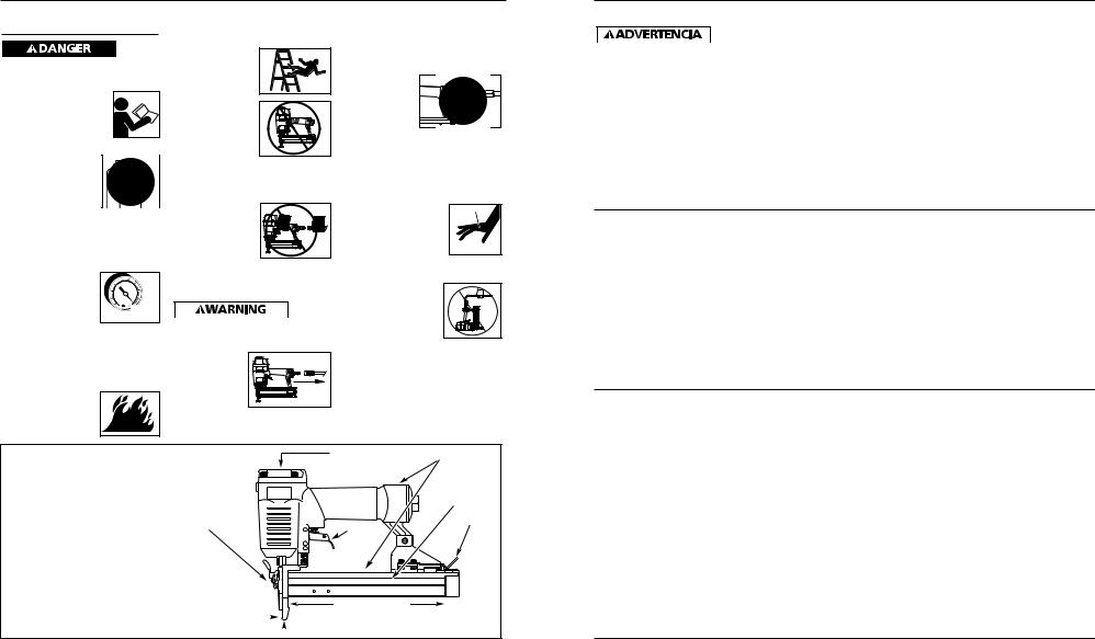
Stapler Components And Specifications
•REQUIRES: .80 SCFM with 10 staples per minute @ 90 psi
•AIR INLET: 1/4” NPT
•STAPLE SIZE RANGE: 1/2” to 1”
•MAGAZINE CAPACITY:
100 Staples per load, 18 gauge
•WEIGHT: 2 lbs., 13 oz.
•LENGTH: 10”
•HEIGHT: 71/2”
•MAXIMUM PRESSURE: 100 psi
•PRESSURE RANGE: 60 - 100 psi
Quick Clear Nose
Work Contact 
Element (WCE)
Cap Exhaust |
Warning Labels |
Magazine
Latch
Trigger
Staple Loading Area
 Staple Discharge Area
www.chpower.com
Modelo SN268K00
Guía de Diagnóstico de Averías
Deje de usar la grapadora inmediatamente si alguno de los si guientes problemas ocurre. repuestos. Podría ocasionarle heridas graves. Cualquier reparación o reemplazo de piezas los
debe hacer un técnico calificado personal de un centro autorizado de servicio.
Problema |
Causa |
Solución |
|
|
|
Hay una fuga de aire en el |
Los anillos en O de la cubierta de la |
Debe reemplazar los anillos en O & chequear el |
área de la válvula del |
válvula del gatillo están dañados. |
funcionamiento del elemento de funcionamiento |
gatillo. |
|
al contacto. |
|
|
|
Hay una fuga de aire entre |
Los tornillos de la cubierta están flojos. |
Debe apretar los tornillos. |
la cubierta y la boquilla. |
Los anillos en O están dañados. |
Debe reemplazar los anillos en O. |
|
||
|
La defensa está dañada. |
Debe reemplazar la defensa. |
|
|
|
Hay una fuga de aire entre |
Los tornillos están flojos. |
Debe apretar los tornillos. |
la cubierta y la tapa. |
El empaque está dañado. |
Debe reemplazar el empaque. |
|
La grapadora deja de grapar una grapa.
La defensa está desgastada. La boquilla está sucia.
La suciedad o daños evitan el desplazamiento libre de las grapas o el mecanismo de impulso en el cargador.
El resorte del mecanismo de impulso está dañado.
El flujo de aire hacia la grapadora es inadecuado.
El anillo en O del pistón está desgastado o le falta lubricación.
Los anillos en O de la válvula del gatillo están dañados.
Hay fugas de aire.
Hay una fuga en el empaque de la tapa.
Debe reemplazar la defensa.
Debe limpiar el canal del sistema de impulso. Debe limpiar el cargador.
Debe reemplazar el resorte.
Chequée las conexiones, la manguera o el compresor.
Debe reemplazar los anillos en O. Lubríquelos.
Debe reemplazar los anillos en O.
Debe apretar los tornillos y las conexiones. Debe reemplazar el empaque.
La grapadora funciona |
La grapadora no está bien lubricada. |
Necesita lubricar la grapadora. |
lentamente o pierde |
La clavadora no está bien lubricada |
Necesita lubricar la clavador |
su potencia. |
El orificio de salida de la tapa está |
Debe reemplazar las partes internas dañadas. |
|
||
|
obstruído. |
|
|
|
|
Hay grapas atascadas en la |
La guía del mecanismo de impulso está |
Debe reemplazar la guía. |
grapadora. |
desgastada. |
|
|
La guía del mecanismo de impulso está |
Debe reemplazar la guía |
|
desgastada |
|
|
Las grapas no son del tamaño adecuado. |
Debe usar las grapas recomendadas para esta |
|
|
grapadora. |
Las grapas están dobladas.
Los tornillos del cargador o de la boquilla están flojos.
El mecanismo de impulso está dañado.
Las grapas están mal colocadas
Reemplácelas con grapas en buenas condiciones. Debe apretar los tornillos.
Debe reemplazar el mecanismo de impulso de grapas.
Vea las instrucciones de cómo cargar/descargar la grapadora
2 |
23 Sp |
Manual de Instrucciones
Servicio Técnico
Si desea hacer alguna pregunta referente a la reparación u operación de las herramientas, o para solicitar copias adicionales de este manual, sírvase llamar a nuestro número especial, 1-800-543-6400.
Sujetadores y Piezas de Repuesto
 Use solamente sujetadores Campbell Hausfeld originales calibre 16 (o su equivalente) - (vea la información sobre intercambio de sujetadores). El desempeño de las herramientas, la
seguridad y la duración pueden disminuir si no se utilizan los sujetadores adecuados. Cuando ordene piezas de repuesto o sujetadores, especifique el número de la pieza.
Para reparar la herramienta
La herramienta debe ser reparada únicamente por personal calificado, y deben usar piezas de repuesto y accesorios originales Campbell Hausfeld, o piezas y accesorios que funcionen de manera equivalente.
Para colocarle los sellos
Cada vez que repare una grapadora deberá limpiarle y lubricarle las partes internas. Le recomendamos que use Parker O-lube o un lubricante equivalente en todos los anillos en O. A cada anillo en O se le debe dar un baño de lubricante para anillos antes de instalarlos. Igualmente, deberá ponerle un poco de aceite a todas las piezas que se mueven y muñones. Finalmente, después de haberla ensamblado y antes de probar la herramienta deberá ponerle unas cuantas gotas de aceite sin detergente 30W u otro aceite similar, en las líneas de aire.
Grapas
Estas grapas para acabado de Campbell Hausfeld los puede comprar en su tienda más cercana. Si necesita ayuda para encontrar un artículo, comuníquese al 1-800-543-6400. Las grapas de Campbell Hausfeld cumplen o exceden las especificaciones Federales FF-N-105B.
|
|
Calibre |
|
|
|
Fusión de |
Grapas |
Grapas |
Modelo # |
Longitud |
de la grapa |
Corona |
Punta |
Acabado |
la linea |
por linea |
por caja |
|
|
|
|
|
|
|
|
|
|
|
|
|
|
|
|
|
|
FN180615AV |
12,7mm (1/2”) |
Calibre 18 |
6,4mm(1/4") |
Cincel |
Galvanizado/Cubierta por vinilo |
Adhesivo |
100 |
1000 |
FN180620AV |
19,1mm (3/4”) |
Calibre 18 |
6,4mm(1/4") |
Cincel |
Galvanizado/Cubierta por vinilo |
Adhesivo |
100 |
1000 |
FN180625AV |
25,4mm (1”) |
Calibre 18 |
6,4mm(1/4") |
Cincel |
Galvanizado/Cubierta por vinilo |
Adhesivo |
100 |
1000 |
|
|
|
|
|
|
|
|
|
Información de intercambio
Las grapas usadas con la grapadora para acabado SN268K de Campbell Hausfeld también se pueden usar con las grapadoras : Senco LN4450, SJS-LR, SKS L11-15, Hitachi N3804A, Duofast BN-1832S, KN-1848, ST-18, Stan-Tech SDS 18-14, Atro Minor 90/30, 90/32, 90/40, y Porter Cable NS100.
Notas
22 Sp
Model SN268K00
General Safety
Information (Continued)
Do not point the tool toward yourself or anyone whether it contains fasteners or not. Accidental triggering of the tool could result in death or serious personal injury.
● Do not drive a fastener on top of other fasteners. The fastener could glance and cause death or a serious puncture wound.
● Do not operate
or allow anyone
else to operate the tool if any warnings or warning labels are not legible.
Warnings or warning labels are located on the tool magazine and body.
●Do not drop or throw the tool. Dropping or throwing the tool can result in damage that will make the tool unusable or unsafe. If the tool has been dropped or thrown, examine the tool closely for bent, cracked or broken parts and air leaks. STOP and repair before using or serious injury could occur.
Caution indicates
a potentially hazardous situation which, if not avoided, MAY result in minor or moderate injury.
●Do not make any modifications to the tool without first obtaining written approval from Campbell Hausfeld. Do not use the tool if any shields or guards are removed or altered. Do not use the tool as a hammer. Personal injury or tool
damage may occur.
●Always check that the Work Contact Element (WCE) is operating properly. A fastener could accidentally be
driven if the WCE is not working properly. Personal injury may occur
(See "Checking the Work Contact Element" Section).
●Disconnect air supply and release tension from the pusher before attempting to clear jams because tools can be ejected from the front of the tool. Personal injury may occur.
Notice indicates
important information, that if not followed, MAY cause damage to equipment.
●Avoid using the tool when the magazine is empty. Accelerated wear on the tool may occur.
●Clean and check all air supply hoses and fittings before connecting the tool to an air supply. Replace any damaged or worn hoses or fittings. Tool performance or durability may be reduced.
●Air compressors providing air to the tool should follow the requirements established by the American National Standards Institute Standard B19.3-1991; Safety Standard for Compressors for Process Industries. Contact your air compressor manufacturer for information.
Operating The
Stapler
Read this manual and understand all safety warnings and instructions before operating the stapler.
LUBRICATION
This stapler requires lubrication before using the stapler for the first time and before each use. If an inline oiler is used, manual lubrication through the air inlet is not required on a daily basis.
The work
surface can become damaged by excessive lubrication. Proper lubrication is the owner’s responsibility. Failure to lubricate the stapler properly will dramatically shorten the life of the stapler and void your warranty.
1. Disconnect the air supply from the stapler to add lubricant.
2.Turn the stapler so the air inlet is fac-
ing up. Place 4-5 |
OIL |
|
|
drops of 30 W non- |
|
detergent oil into |
|
air inlet. Do not use |
|
detergent oils, oil |
|
additives, or air tool |
|
oils. Air tool oils |
|
contain solvents which will damage |
|
the stapler's internal components. |
|
3. After adding oil, |
|
run stapler |
|
briefly. Wipe off |
|
any excess oil |
|
from the cap |
|
exhaust. |
|
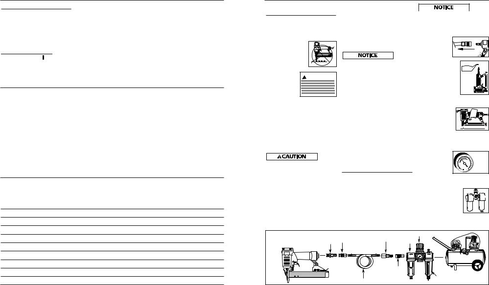
RECOMMENDED HOOKUP
The illustration below shows the recommended hookup for the stapler.
1. The air com-
pressor must be able to
maintain a minimum of 60 psi when
the stapler is being used. An inadequate air supply can cause a loss of power and inconsistent driving.
2. An oiler can be used
to provide oil 

 circulation through


 the stapler. A filter


 can be used to


 remove liquid and
  solid impurities which
can rust or “gum up” internal parts of the stapler.
Recommended Hookup |
Quick |
Quick |
Quick Plug |
Regulator |
|
Coupler |
(Optional) |
Oiler |
|
|
Plug |
|||
|
|
|
Quick |
|
|
|
|
Coupler |
|
|
|
|
(Optional) |
Filter |
|
|
|
Air Hose |
|
|
|
|
|
www.chpower.com |
|
|
|
3 |
|

Operating Instructions
Operating The
Stapler (Continued)
3. Use 3/8” air
hoses with a minimum
working pressure of 150 psi. Use 1/2”
air hoses for 50’ run or longer. For better performance, install a 3/8” quick plug (1/4” NPT threads) with an inside diameter of .315" (8mm) on the stapler and a 3/8” quick coupler on the air hose.
4.Use a pressure regulator on the compressor, with an operating pressure of 0 - 125 psi. A pressure regulator is required to control the operating pressure of the stapler between 60 and 100 psi.
Sequential Trip Safety Mechanism
This tool is equipped with a sequential trip safety mechanism. When the operator depresses the Work Contact Element (WCE) against the work surface and then pulls the trigger, a fastener will be driven.
OPERATING A SEQUENTIAL TRIP STAPLER
1. Release trigger and place nose of tool against work surface.
2. Depress the
Work contact
element (WCE) against the
work surface and pull the trigger to
drive a fastener.
3. Release the trigger and lift the tool from the work surface after each fastener is driven.
CHECKING THE WORK CONTACT ELEMENT (WCE)
Check the operation of the Work Contact Element (WCE) trip
mechanism before each use. The WCE must move freely without binding through its entire travel distance. The
WCE spring must return the WCE to its fully extended position after being
depressed. Do not operate the stapler if the WCE trip mechanism is not operating properly. Personal injury may occur.
1.Disconnect the air supply from the stapler.
2.Remove all
|
staples from |
|
|
the magazine |
|
|
(See Loading- |
|
|
Unloading). |
|
3. |
Make sure the |
|
|
trigger and |
|
|
Work Contact |
|
|
Element (WCE) |
movement |
|
move freely up |
|
|
|
|
|
and down |
|
|
without stick- |
|
|
ing or binding. |
|
4. |
Reconnect air |
|
|
supply to the |
|
|
stapler. |
|
5. |
Depress the |
|
|
work contact |
|
|
element |
|
|
(WCE) against |
|
|
the work sur- |
|
|
face without |
|
|
pulling the |
|
|
trigger. The stapler MUST NOT |
|
|
OPERATE. Do not use the stapler if |
|
|
it operates without pulling the trig- |
|
|
ger. Personal injury may result. |
|
6. |
Remove the |
|
|
stapler from the |
|
|
work surface. |
|
|
The Work |
|
|
Contact Element |
|
|
(WCE) must |
|
|
return to its original down position. |
|
|
Pull the trigger. The stapler MUST |
|
|
NOT OPERATE. Do not use the sta- |
|
|
pler if it operates while lifted from |
|
|
the work surface. Personal injury |
|
|
may result. |
|
7.Depress the Work Contact
Element (WCE) against
the work surface. Pull the trigger. The stapler MUST operate.
LOADING/UNLOADING THE STAPLER
1. |
Always connect the tool to the air |
|
|
supply before loading fasteners. |
|
2. |
Push down |
Latch |
|
on the latch |
Button |
|
button. Pull |
|
|
back on the |
|
|
magazine |
|
|
cover. |
|
3.For staples, load a clip of staples with the crowns straddling the magazine rail.
Magazine rail |
4. Push the magazine cover forward until latch button pops up.
5.Always unload all fasteners before removing tool from service. Unloading is the reverse of loading, except always disconnect the air supply before unloading.
ADJUSTING THE STAPLE
PENETRATION
1.Regulate the air pressure to 60 psi at the stapler.
2.Connect the air supply and test for penetration by driving staples into a sample piece of wood. If the staples do not achieve the desired penetration, adjust the air pressure to a higher setting until the desired penetration is achieved. Do not exceed 100 psi at the stapler or durability of the stapler will be reduced.
www.chpower.com
Modelo SN268K00
Cómo usar la
grapadora (Continuación)
4. Reconecte la grapadora a la fuente de suministro de aire.
5. Presione el
Elemento de Contacto de
Trabajo contra la superficie de trabajo sin
apretar el gatillo. La grapadora NO DEBE OPERAR. No use la herramienta si opera sin apretar el gatillo. Se pueden producir lesiones personales.
6. Remueva la
grapadora de la superficie
de trabajo. El Elemento de Contacto de
Trabajo tiene que volver a su posición original. La grapadora NO DEBE OPERAR. No use la herramienta si opera mientras está levantada de la superficie de trabajo.
7. Apriete el
gatillo y presione
el Elemento
de Contacto de Trabajo contra la superficie de trabajo. La grapadora
DEBE OPERAR.
PARA CARGAR Y DESCARGAR LA GRAPADORA
1. Siempre conecte la herramienta a |
||
|
la fuente de suminsitro de aire |
|
|
antes de colocarle los sujetadores. |
|
2. |
Empuje hacia |
Botón del |
|
abajo sobre |
|
|
seguro |
|
|
el boton del |
|
|
|
|
|
seguro. |
|
|
Mueva la |
|
|
tapa del |
|
|
cargador |
|
|
hacia atrás. |
|
3.Para grapas, cargue una tira de grapas con las coronas montadas sobre el riel del cargador.
Carril del cargador |
4. Empuje la tapa del cargador hacia delante hasta que el botón del seguro salte hacia arriba.
5.Siempre descargue el sujetador antes de remover la herramienta de servicio. La descarga se hace siguiendo el proceso inverso de la carga; sin embargo, siempre se tiene que desconectar la manguera de aire antes de descargarla.
PARA AJUSTAR LA PENETRACION DE LAS GRAPAS
1.Regule la presión de aire en la grapadora a 4,14 bar.
2.Conecte las mangueras de aire y pruebe la penetración clavando unas grapas en un pedazo de madera. Si éstos no penetran hasta el nivel deseado, aumente la presión de aire y pruebe una vez más, conmtinue haciendolo hasta lograr los resultados deseados. La presión de la grapadora no debe exceder 690 bar ya que ésto reduciría la durabilidad de la grapadora.
QUE HACER CUANDO LA GRAPADORA TENGA UNA GRAPA ATASCADA
1. Desconecte la
clavadora de la fuente de
suministro de aire.
2. Remueva
todos los clavos del
depósito (vea Para Cargar /
Descargar la Clavadora). De lo contrario, hará que los clavos se expulsen desde la parte delantera de la clavadora cuando se remueve el conjunto de la boca.
3. Hale hacía adelante la
lengüeta roja de la boquilla de
desatasco rápido. Aleje la portezuela para
exponer y desatascar el sujetador atascado.
4.Vuelva a colocar la boquilla revertiendo la secuencia del paso 3.
5. Asegúrese que el |
|
gatillo funciona y |
|
que el Elemento |
|
de Contacto de |
movemiento |
Trabajo se mueve |
|
libremente hacia arriba y hacia abajo sin atascarse o pegarse.
4 |
21 Sp |
 Loading...