


CHN50399
36
Operating Instructions and Parts Manual
Instructions d’Utilisation et Manual de Pièces
Manual de Instrucciones y Lista de Piezas
Notes
Notas
This manual contains safety,
operational and maintenance
information. Contact your Campbell
Hausfeld representative if you have
any questions.
Table of Contents
General Safety . . . . . . . . . . . . 1-3
Specifications . . . . . . . . . . . . . . . 2
Operating The Nailer . . . . . . . 4-7
Troubleshooting . . . . . . . . . . . . 7
Parts List . . . . . . . . . . . . . . . . . 8-9
Warranty . . . . . . . . . . . . . . . . . 10
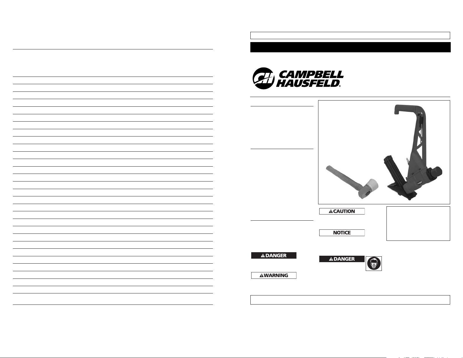
Description
This nailer is designed for use in
installing 3/4" and 1/2" thick
unfinished hardwood flooring. It can
be used to install pre-finished flooring
however caution must be used so the
finish is not damaged by the tool.
UNPACKING
When unpacking, check and make sure
that all the accessories are included. If
anything is missing or broken, please
call 1-800-543-6400 first for assistance.
General Safety
Information
This manual contains information that
is very important to know and
understand. This information is
provided for SAFETY and to PREVENT
EQUIPMENT PROBLEMS. To help
recognize this information, observe the
following symbols.
Danger
indicates
an imminently hazardous situation
which, if not avoided, will result in
death or serious injury.
Warning
indicates
a potentially hazardous situation
which, if not avoided, COULD result in
death or serious injury.
Caution
indicates
a potentially hazardous situation
which, if not avoided, MAY result in
minor or moderate injury.
Notice
indicates
important information, that if not
followed, may cause damage to
equipment.
CALIFORNIA PROPOSITION 65
You can create dust when
you cut, sand, drill or grind
materials such as wood, paint, metal,
concrete, cement, or other masonry.
This dust often contains chemicals
known to cause cancer, birth defects,
or other reproductive harm.
Wear protective gear.
Operating Instructions and Parts Manual Model CHN50399
BUILT TO LAST
Flooring
Nailer / Stapler
Please read and save these instructions. Read carefully before attempting to assemble, install, operate or maintain the product described.
Protect yourself and others by observing all safety information. Failure to comply with instructions could result in personal injury, death and/or
property damage! Retain instructions for future reference.
IN715200AV 3/07
© 2007 Campbell Hausfeld/Scott Fetzer
See Warranty on page 10 for important information about commercial use of this product.
For parts, product & service information
visit www.chpower.com
Locate model number on magazine
and date code on tool body; record
below:
Model No. ________________________
Date Code ________________
Retain these numbers for
future reference.
REMINDER: Keep your dated proof of purchase for warranty purposes! Attach it to this manual or file it for safekeeping.
35
Model
Modèle CHN50399
Modelo
Notes
Notas
2
General Safety
Information (Continued)
OPERATOR’S RESPONSIBILITY:
The tool operator is responsible for:
• Reading and understanding tool
labels and manual.
• Selecting an appropriate tool
actuation system, taking into
consideration the work application
for which the tool is used.
• The safe use of the tool.
• Ensuring that the tool
is used only when the
operator and all other
personnel in the work
area are wearing ANSI
Z87 eye protection equipment, and
when required, other appropriate
protection equipment such as head,
hearing and foot protection
equipment. Serious eye or
permanent hearing loss could
result.
• Assuring that the tool is kept in
safe working order as described in
this manual.
EMPLOYER’S RESPONSIBILITY:
• Selecting an appropriate tool
actuation system, taking into
consideration the work application
for which the tool is used.
• Ensuring that this manual is
available to operators and
personnel performing
maintenance.
• The safe use of the tool.
• Enforcing that the tool
is used only when the
operator and all other
personnel in the work
area are wearing ANSI
Z87 eye protection equipment, and
when required, other appropriate
protection equipment such as head,
hearing and foot protection
equipment. Serious eye or
permanent hearing loss could
result.
• Assuring that the tool is kept in
safe working order as described in
this manual.
• Assuring the proper maintenance
of all tools in employer’s
possession.
• Ensuring that tools which require
repair are not further used before
repair. Tags and physical
segregation are recommended
means of control.
Read and understand
tool labels and manual.
Failure to follow
warnings, dangers, and
cautions could result in
DEATH or SERIOUS INJURY.
Do not use any type of
reactive gases,
including, but not
limited to, oxygen and
combustible gases, as a
power source. Use filtered,
lubricated, regulated compressed air
only. Use of a reactive gas instead of
compressed air may cause the nailer
to explode which will cause death or
serious personal injury.
Use only a pressure-
regulated compressed
air source to limit the
air pressure supplied to
the tool. The regulated
pressure must not exceed 90 psi. If
the regulator fails, the pressure
delivered to the tool must not
exceed 200 psi. The nailer could
explode which will cause death or
serious personal injury.
Never use gasoline or
other flammable liquids
to clean the nailer.
Never use the nailer in
the presence of
flammable liquids or gases. Vapors
could ignite by a spark and cause an
explosion which will result in death
or serious personal injury.
Operating Instructions and Parts Manual
• REQUIRES: 4.3 Avg SCFM using
60 fasteners at 80 psi
• AIR INLET: 1/4" NPT
• FASTENER SIZE RANGE:
15 1/2 gauge 1/2" crown
flooring staples: 1 1/2" to 2"
16 gauge L- head flooring
cleats: 1 1/2" to 2"
• MAGAZINE CAPACITY:
110 fasteners
• WEIGHT: 10.0 lbs.
• LENGTH: 16.5"
• HEIGHT: 23"
• MAXIMUM PRESSURE: 90 psi
• PRESSURE RANGE: 70 - 90 psi
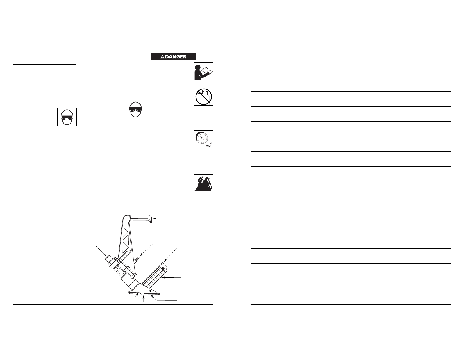
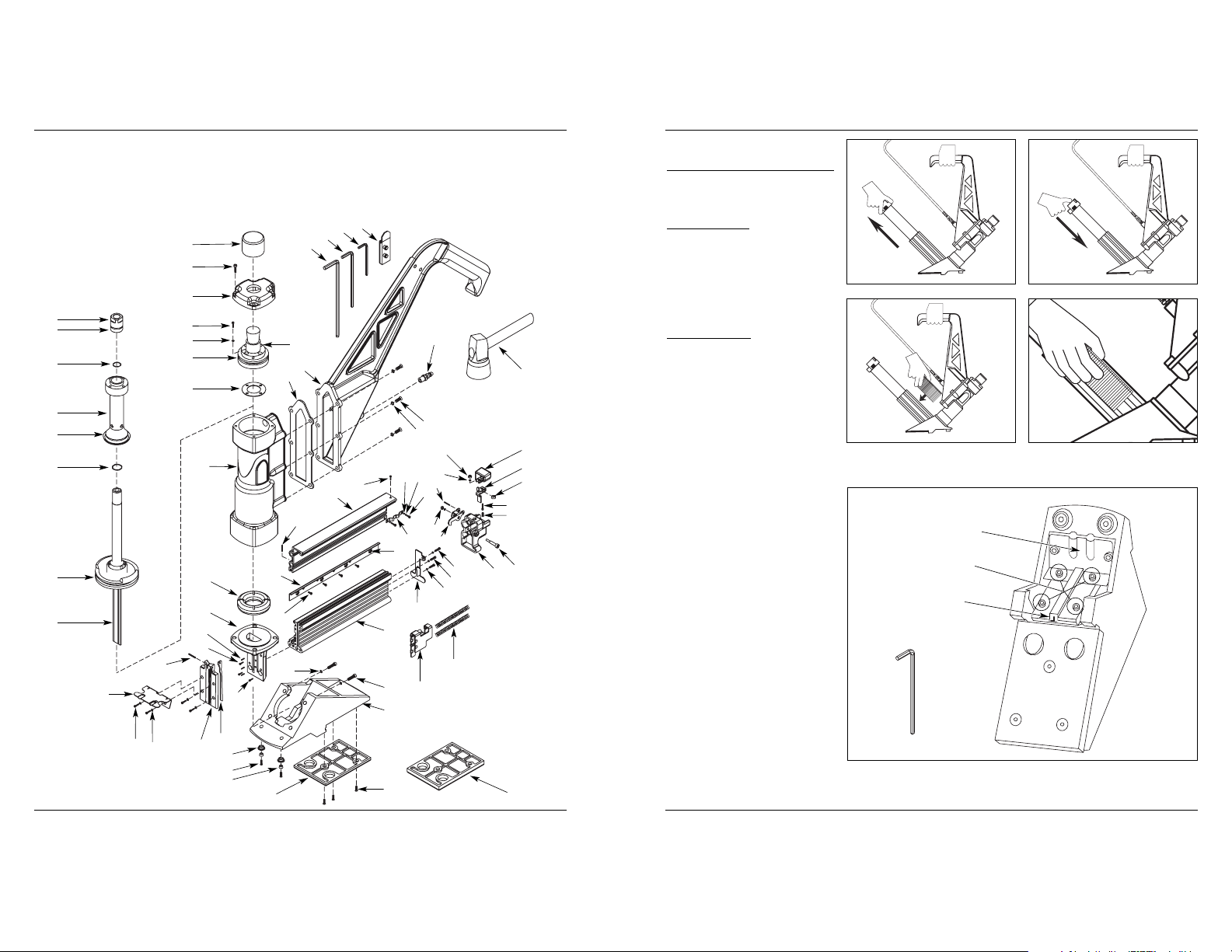
Nailer / Stapler Components And Specifications
www.chpower.com
Magazine
O
CO
2
90
Carry handle
Rubber bumper
Inlet
Magazine lock button
Shoe
Shoe plate
Nose
Fastener ejection area
34 Sp
Modelo CHN50399
Manual de Instrucciones y Lista de Piezas
Garantía Limitada
1 DURACION: A partir de la fecha de compra por el comprador original tal como se especifica a continuación: Productos
Estándard (Standard Duty) - Un año, Productos Resistentes (Serious Duty) -Dos años, Productos Robustos (Extreme Duty)
- Tres años.
2. QUIEN OTORGA ESTA GARANTIA (EL GARANTE: Campbell Hausfeld / The Scott Fetzer Company 100 Production Drive,
Harrison, Ohio 45030 Teléfono: (800) 543-6400
3. QUIEN RECIBE ESTA GARANTIA (EL COMPRADOR): El comprador original (que no sea un revendedor) del producto
Campbell Hausfeld.
4. PRODUCTOS CUBIERTOS POR ESTA GARANTIA: Cualquier clavadora, grapadora, herramienta neumática,
pistola pulverizadora, inflador o accesorio neumático suministrado o fabricado por el Garante.
5. COBERTURA DE LA GARANTIA: Los defectos substanciales de material y fabricación que ocurran dentro del período
de validez de la garantía.
6. LO QUE NO ESTA CUBIERTO POR ESTA GARANTIA:
A. Las garantías implícitas, incluyendo aquellas de comercialidad E IDONEIDAD PARA FINES PARTICULARES,
ESTAN LIMITADOS A LO ESPECIFICADO EN EL PARRAFO DE DURACION. Si este producto es empleado para uso
comercial, industrial o para renta, la garantía será aplicable por noventa (90) días a partir de la fecha de compra.
En algunos estados no se permiten limitaciones a la duración de las garantías implícitas, por lo tanto, en tales casos
esta limitación no es aplicable.
B. CUALQUIER PERDIDA DAÑO INCIDENTAL, INDIRECTO O CONSECUENTE QUE PUEDA RESULTAR DE UN DEFECTO,
FALLA O MALFUNCIONAMIENTO DEL PRODUCTO CAMPBELL HAUSFELD. En algunos estados no se permite la
exclusión o limitación de daños incidentales o consecuentes, por lo tanto, en tales casos esta limitación o exclusión
no es aplicable
C. Cualquier falla que resulte de un accidente, abuso, negligencia o incumplimiento de las instrucciones de
funcionamiento y uso indicadas en el (los) manual(es) que se adjunta(n) al producto. Dichos accidentes,
abusos por parte del comprador, o falta de operar el producto siguiendo las instrucciones del manual de
instrucciones suministrado también debe incluir la desconexión o modificación de los instrumentos de seguridad.
Si dichos instrumentos de seguridad son desconectados, la garantía quedaría cancelada.
D. Los ajustes normales explicados en el(los) manual(es) suministrado(s) con el producto.
E. Artículos o servicios normalmente requeridos para el mantenimiento del producto, tales como: anillos en O,
resortes, amortiguadores, defensas, hojas de impulsor
, fusibles, baterías, empaques, almohadillas o sellos, boquillas
de fluído, agujas, boquillas para rociar arena
, lubricantes, mangueras de material, elementos filtrantes, álabes de
motores, abrasivos, hojillas, discos para cortar, cinceles, retenes para cinceles, cortadores, collarines, mandriles,
mordazas para remachadoras, brocas para desarmadores
, almohadillas para lijar, soportes de almohadillas,
mecanismo de impacto
o cualquier otro artículo desgastable que no se haya enumerado específicamente.
Estos artículos sólo estarán cubiertos bajo esta garantía por noventa (90) días a partir de la fecha de
compra original. Los artículos subrayados sólo están garantizados por defectos de material o fabricación
.
7. RESPONSABILIDADES DEL GARANTE BAJO ESTA GARANTIA: Reparar o reemplazar, como lo decida el Garante,
los productos o componentes que estén defectuosos, se hayan dañado o hayan dejado de funcionar adecuadamente,
durante el período de validez de la garantía
8. RESPONSABILIDADES DEL COMPRADOR BAJO ESTA GARANTIA:
A. Suministrar prueba fechada de compra y la historia de mantenimiento del producto.
B. Entregar o enviar el producto o componente Campbell Hausfeld al Centro de Servicio autorizado Campbell
Hausfeld más cercano. Los gastos de flete, de haberlos, deben ser pagados por el comprador.
C. Seguir las instrucciones sobre operación y mantenimiento del producto, tal como se indica(n) en el (los) manual(es)
del propietario
9. CUANDO EFECTUARA EL GARANTE LA REPARACION O REEMPLAZO CUBIERTO BAJO ESTA GARANTIA: La reparación
o reemplazo dependerá del flujo normal de trabajo del centro de servicio y de la disponibilidad de repuestos.
Esta garantía limitada es válida sólo en los EE.UU., Canadá y México y otorga derechos legales específicos. Usted también
puede tener otros derechos que varían de un Estado a otro. o de un país a otro.
3
General Safety
Information (Continued)
Make sure tool is securely placed
before firing (see Operating the
Nailer section). If tool is not securely
placed, there is a risk of flying
fasteners that may cause death or
serious injury.
Make sure mallet head is secure to
mallet handle. Do not use if head is
not secure. A non-secure head may
fly off and cause death or severe
personal injury.
Always use the rubber end of the
mallet only for striking the rubber
bumper. Damage to the tool may
occur if you use the metal end. The
metal end is only to be used for
racking the flooring boards.
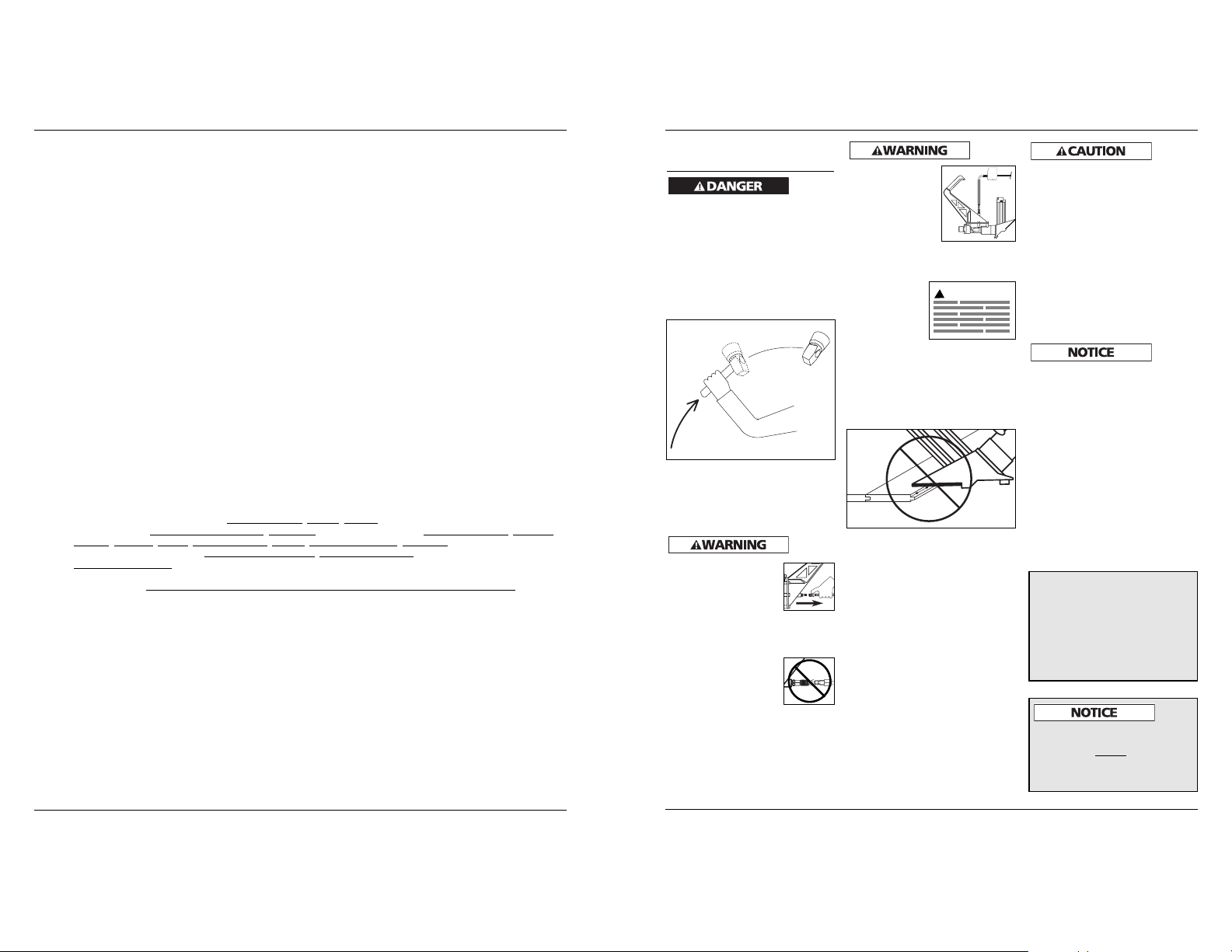
Always disconnect the
tool from the power
source when
unattended, performing
any maintenance or
repair, clearing a jam, or
moving the tool to a new location.
Always reconnect the air line
BEFORE loading any fasteners.
Always fit tool with a
fitting or hose coupling
on or near the tool in
such a manner that all
compressed air in the
tool is discharged at the
time the fitting or hose coupling is
disconnected. Do not use a check
valve or any other fitting which
allows air to remain in the nailer.
Death or serious personal injury
could occur.
Do not make any modifications to
the tool without first obtaining
written approval from Campbell
Hausfeld. Do not use the nailer if
any shields or guards are removed
or altered. Do not use the nailer as a
hammer. Personal injury or tool
damage may occur.
Avoid long extended periods of
work with the nailer. Stop using the
nailer if you feel pain in hands or
arms.
Do not place tool on pre-finished
flooring in an abusive manner.
Careless placement of the tool may
mar or damage the flooring.
Avoid using the nailer when the
magazine is empty. Accelerated
wear on the nailer may occur.
Clean and check all air supply hoses
and fittings before connecting the
nailer to an air supply. Replace any
damaged or worn hoses or fittings.
Tool performance or durability may
be reduced.
Air compressors providing air to the
nailer should follow the
requirements established by the
American National Standards
Institute Standard B19.3-1991;
Safety Standard for Compressors for
Process Industries. Contact your air
compressor manufacturer for
information.
Never carry the
nailer by the air
hose or pull the
hose to move the
nailer or a
compressor. Keep
hoses away from
heat, oil and sharp
edges. Replace any hose that is
damaged, weak or worn. Personal
injury or tool damage could occur.
Do not operate
or allow
anyone else to
operate the
nailer if any
warnings or
warning labels
are not legible. Warnings or
warning labels are located on the
nailer magazine and body.
Do not drive a nail on top of other
nails. The nail could glance and
cause death or a serious puncture
wound.
Always assume the nailer contains
nails. Respect the tool as a working
implement; no horseplay. Always
keep others at a safe distance from
the work area in case of accidental
discharge of nails. Do not point the
tool toward yourself or anyone
whether it contains fasteners or not.
Accidental triggering of the nailer
could result in death or serious
personal injury.
Do not drop or throw the tool.
Dropping or throwing the tool can
result in damage that will make the
tool unusable or unsafe. If the tool
has been dropped or thrown,
examine the tool closely for bent,
cracked or broken parts and air
leaks. STOP and repair before using
or serious injury could occur.
Model CHN50399
www.chpower.com
The DANGER, WARNING, CAUTION,
and NOTICE notifications and
instructions in this manual cannot
cover all possible conditions and
situations that may occur. It must be
understood by the operator that
common sense and caution are factors
which cannot be built into this
product, but must be supplied by the
operator.
!
WARNING
READ ALL FLOORING MANUFACTURER
WARNINGS, PROCEDURES, AND
INSTRUCTIONS BEFORE
USING THIS
TOOL. THE INFORMATION PROVIDED
BY THE FLOORING MANUFACTURER
MUST BE FOLLOWED.
Lista de Repuestos
No. de Número de
Ref Descripción Repuesto Ctd
No. de Número de
Ref Descripción Repuesto Ctd
33 Sp
Modelo CHN50399
1 Cabeza del pistón SX140100AV 1
2 Anillo en O - 19.2 x 1.8 1
3 Anillo en O - 15.9 x 1.8 1
4 Cilindro de válvula SX140400AV 1
5 Anillo en O - 42.5 x 5.4 1
6 Anillo en O - 17.5 x 2.6 1
7 Anillo en O - 57.4 x 3.5 1
8 Ensamblaje del pistón SX140800AV 1
9 Defensa de caucho SX140900AV 1
10 Tornillo - M5 x 20 1
11 Sombrerete SX141100AV 1
12 Tornillo - M4 x 20 1
13 Arandela de resorte 1
14 Actuador SX141400AV 1
15 Anillo en O - 54.2 x 3.5 1
16 Sello 1
17 Cuerpo -- 1
18 Defensa SX141800AV 1
19 Boquilla SX141900AV 1
20 Tornillo - M3 x 20 1
21 Pasador de resorte - 3 x 14 1
22 Protector contra el polvo SX142200AV 1
23 Tornillo - M5 x 14 1
24 Arandela de resorte 1
25 Guía de la cuchilla SX142500AV 1
26 Guía de puntillas dentadas SX142600AV 1
27 Zapata -- 1
28 Pata de goma SX142800AV 2
29 Casquillo SX142900AV 1
30 Tornillo - M6 x 16 1
31a Placa de zapata gruesa,
5/16" (8 mm) SX143100AV 1
31b Placa de zapata delgada,
1/4" (6 mm) SX143200AV 1
32 Tornillo - M6 x 12 1
33 Pasador de resorte - 2 x 14 1
34 Cargador SX143500AV 1
35 Arandela de resorte 1
36 Tornillo - M6 x 35 1
37 Impulsor SX143800AV 1
38 Resorte de empuje SX143900AV 2
39 Placa terminal del cargador SX144000AV 1
40 Tapa del extremo
del cargador SX144100AV 1
41 Tornillo 1
42 Resorte SX144300AV 1
43 Tornillo - M4 x 16 1
44 Placa tope SX144500AV 1
45 Botón de seguro
del cargador SX144600AV 1
46 Tuerca - M4 1
47 Arandela 1
48 Buje SX144900AV 1
49 Pasador de resorte - 3 x 12 1
50 Gancho de seguro
del cargador SX145100AV 1
51 Tornillo - M3 x 5 1
52 Arandela 1
53 Arandela de resorte 1
54 Resorte de hoja SX145500AV 1
55 Tornillo - M3 x 8 1
56 Puerta del cargador SX145700AV 1
57 Pasador de resorte - 2.5 x 10 1
58 Tornillo - M3 x 6 1
59 Magneto SX146000AV 3
60 Riel SX146100AV 1
61 Empaque SX146200AV 1
62 Brazo -- 1
63 Tornillo - M6 x 25 1
64 Tapón de aire 1
65 Llave 5 mm 1
66 Llave 4 mm 1
67 Llave 3 mm 1
68 Soporte de llaves 1
69 Martillo SX147000AV 1
REPLACEMENT PARTS KITS
Juego completo
de anillos en O SKN09100AV
Juego de llaves SKN09200AV
Artículo estándar de ferretería - disponible en su
ferretería local
Operating The Nailer
LUBRICATION
This nailer requires lubrication before
using the nailer for the first time and
before each use. If an inline oiler is
used, manual lubrication through the
air inlet is not required on a daily
basis.
The work
surface
can become damaged by excessive
lubrication. Proper lubrication is the
owner’s responsibility. Failure to
lubricate the nailer properly will
dramatically shorten the life of the
nailer and void your warranty.
1. Disconnect the air
supply from the nailer
to add lubricant.
2. Turn the nailer
so the air inlet
is facing up.
Place 4-5 drops
of 30 W non-
detergent oil
into air inlet.
Do not use
detergent oils,
oil additives, or
air tool oils which contain solvents.
This will damage the nailer’s
internal components.
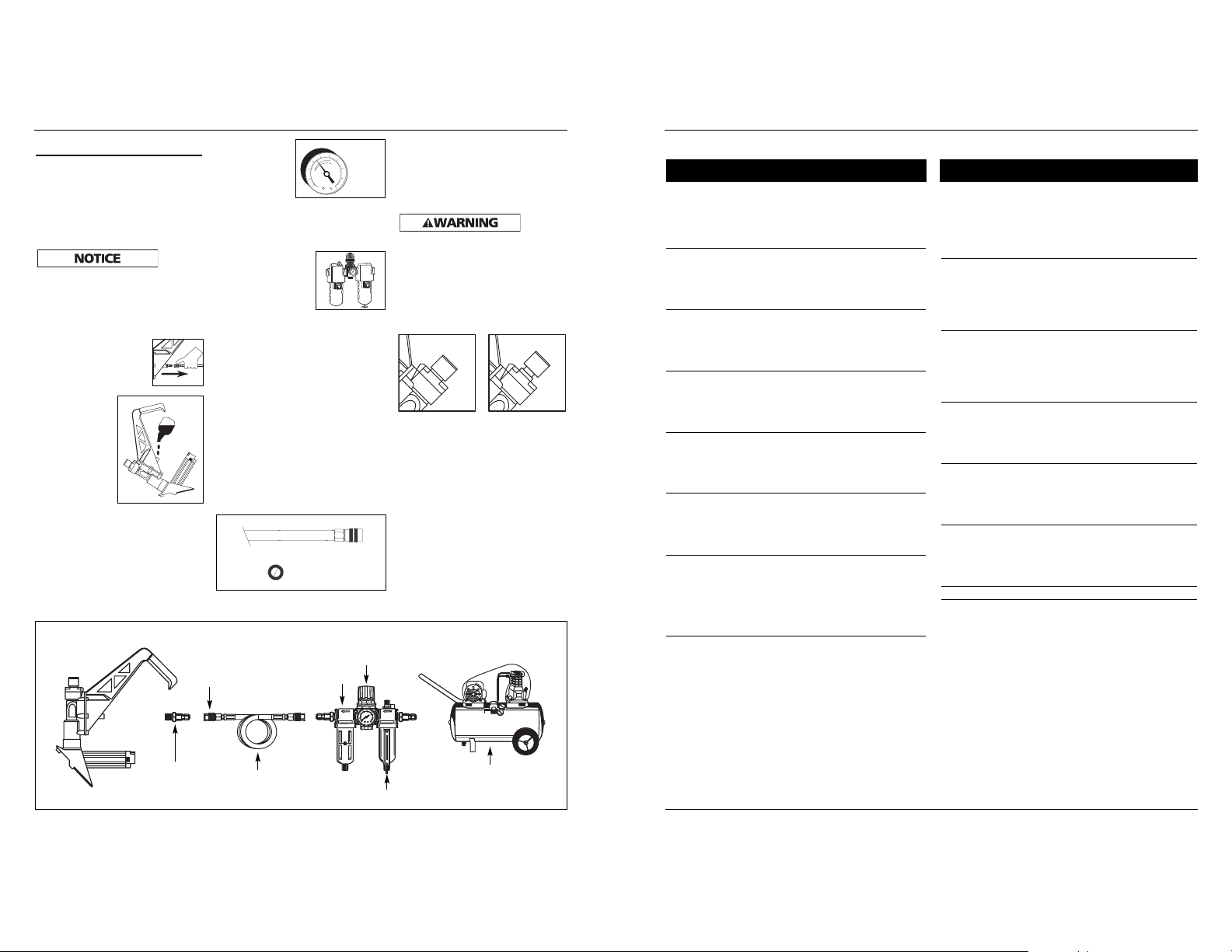
RECOMMENDED HOOKUP
The illustration below shows the
recommended hookup for the nailer.
1. The air
compressor
must be able
to maintain a
minimum of
70 psi when the nailer is being
used. An inadequate air supply can
cause a loss of power and
inconsistent driving.
2. An oiler can be
used to provide oil
circulation through
the nailer. A filter
can be used to
remove liquid and solid impurities
which can rust or “gum up”
internal parts of the nailer.
3. Always use air supply hoses with a
minimum working pressure rating
equal to or greater than the
pressure from the power source if
a regulator fails, or 150 psi,
whichever is greater. Use 3/8" air
hose for runs up to 50'. Use 1/2" air
hoses for 50' run or longer. For
better performance, install a 3/8"
quick plug (1/4" NPT threads) with
an inside diameter of .315" (8 mm)
on the nailer and a 3/8" quick
coupler on the air hose.
Operating Instructions and Parts Manual
4
www.chpower.com
150 psi or greater
3/8" I.D.
70 psi
Min.
90 psi
Max.
Recommended Hookup
Quick
Plug
Quick
Coupler
Air
Hose
Air Supply
Oiler
Regulator
Filter
4. Use a pressure regulator on the
compressor, with an operating
pressure of 0 - 125 psi. A pressure
regulator is required to control the
operating pressure of the nailer
between 70 and 90 psi.
An
improperly functioning tool must not
be used. Do not actuate the tool unless
the tool is placed firmly against the
work piece.
Note: Make sure the rubber bumper
on the flooring nailer is in the up
position before adding the air hose,
if not, the nailer may cycle (see below).
Rubber Bumper
Down Position
Rubber Bumper
Up Position
32 Sp
Manual de Instrucciones y Lista de Piezas
Para Ordenar Repuestos o Asistencia Técnica, Sírvase Llamar
al Distribuidor Más Cercano a Su Domicilio
Sírvase proporcionar la siguiente información:
- Número de modelo
- Número de serie (si tiene)
- Descripción y número de la pieza como se muestra en la lista de repuestos
Dirija toda la correspondencia a:
Campbell Hausfeld
Attn: Customer Service
100 Production Drive
Harrison, OH 45030 U.S.A.
14
1
3
4
6
7
2
5
8
9
10
11
12
13
15
16
17
18
19
33
20
21
22
23
24
25
26
10
64
69
28
30
29
31b
32
27
36
35
37
38
34
58
60
59
39
13
12
23
40
41
42
43
48
44
45
46
47
49
54
50
46
53
52
51
55
57
56
62
61
35
63
68
67
66
65
31a
Figure 5
Operating The Nailer
(Continued)
LOADING/UNLOADING THE NAILER
Always connect the tool to the air
supply before loading fasteners.
Loading the staples
1. Hold the tool firmly, press the lock
and pull the magazine door
(See figure 1).
2. Place the staples straddling the top
of the magazine (See figure 2).
3. Push and lock the magazine door
back in place (See figure 3).
Loading the L cleats
1. Hold the tool firmly, press the
lock and pull the magazine
(See figure 1).
2. Place the specified type and size of
L cleats in the magazine from side.
The head of the L cleats should be
inserted into the notch on the fixed
magazine (See figure 4).
3. Push and lock the magazine door
back in place (See figure 3).
CLEARING A JAM FROM THE NAILER
(SEE FIGURE 5)
1. Disconnect the air supply from the
nailer.
2. Remove staples or L cleats from
magazine.
3. Using provided 4 mm wrench,
remove the four nose plate screws,
washers, nose plate, and dust
shield.
4. Using a small tool, pick out the
jammed fastener.
5. Reattach all hardware (apply a
good quantity of threadlock glue
on screw threads before installing;
tighten firmly).
Model CHN50399
5
www.chpower.com
Figure 1
Figure 2
Figure 3
Figure 4
4 mm Wrench
Nose Plate Screws
Nose Plate
Dust shield
31 Sp
Modelo CHN50399
Notas
Operating The Nailer
(Continued)
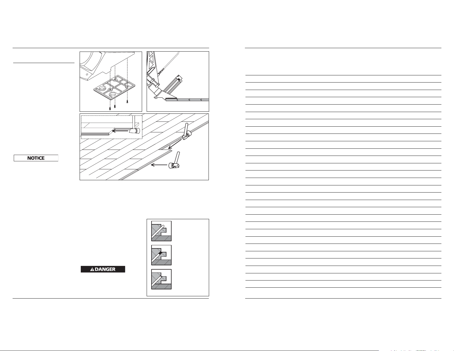
CHANGING SHOE PLATES
1. Disconnect the air supply from
the nailer.
2. Using provided 4 mm wrench,
remove the three shoe screws.
3. Remove shoe plate; place new or
alternate shoe. Make sure shoe is in
the “up” position when attaching
(See Figure 6).
4. Reattach screws (apply a good
quantity of threadlock glue on
screw threads before installing;
tighten firmly).
SHOE PLATE SIZES
There are two shoe plates included
with this tool. The 1/4" thin plate is for
use on 3/4" thick hardwood flooring.
The 5/16" thick plate is for use on 1/2"
thick hardwood flooring.
To
prevent
damage to the flooring, use the correct
shoe for the flooring being installed.
RACKING THE FLOORING
(SEE FIGURE 7)
First refer to flooring manufacturer’s
preparation procedures regarding
moisture content and floor
preparation before laying the flooring
boards.
To correctly install hardwood flooring,
it must be properly racked before
being nailed into place. After placing
the first board, follow these
instructions to rack the flooring:
1. Place flooring groove onto the
tongue of previously installed
board.
2. Use the rubber end of the mallet to
“pop” the tongue into the groove.
3. Use the metal end of the mallet to
rack the board tightly against
adjacent board.
FIRING THE NAILER
1. Connect the air supply to the nailer.
Note: Make sure the rubber bumper
on the flooring nailer is in the up
position before adding the air hose,
if not, the nailer may cycle.
2. Load fasteners (see Loading the
Nailer Section).
3. Place the tool on the floor as
shown in Figure 8 with the shoe
plate resting on the racked floor
board. Make sure the fastener
ejection nozzle is firmly placed
against the board tongue.
4. Strike the tools rubber bumper
firmly with the rubber end of the
mallet. The tool should cycle and
drive fastener into floor board.
Do NOT
fire the
tool unless it is securely placed. If tool
is not securely placed, there is a risk of
flying fasteners that may cause death
or serious injury.
Operating Instructions and Parts Manual
6
www.chpower.com
UP Position of
Shoe plate
Figure 6
Figure 7
Alternate Racking View
Racking
Popping
Figure 8
FASTENER DEPTH & PLACEMENT
Refer to Figure 9 for correct depth
placement of fasteners in hardwood
tongue. Use a scrap piece of the
flooring to help determine correct air
pressure settings. Damage to the
tongue upon installation will make
remaining project difficult.
Fastener seated High
Air Pressure too LOW
Figure 9
Fastener seated Low
Air Pressure too HIGH
Fastener seated
Correctly
Air Pressure set
Correctly
 Loading...