


SmartSTACK 100
ELS100-24TX
ETHERNET SWITCH
INSTALLATION
AND
USER GUIDE

Only qualified personnel should perform installation procedures.
NOTICE
Cabletron Systems reserves the right to make changes in specifications and other information contained in this document without prior notice. The reader should in all cases consult Cabletron Systems to determine whether any such changes have been made.
The hardware, firmware, or software described in this manual is subject to change without notice.
IN NO EVENT SHALL CABLETRON SYSTEMS BE LIABLE FOR ANY INCIDENTAL, INDIRECT, SPECIAL, OR CONSEQUENTIAL DAMAGES WHATSOEVER (INCLUDING BUT NOT LIMITED TO LOST PROFITS) ARISING OUT OF OR RELATED TO THIS MANUAL OR THE INFORMATION CONTAINED IN IT, EVEN IF CABLETRON SYSTEMS HAS BEEN ADVISED OF, KNOWN, OR SHOULD HAVE KNOWN, THE POSSIBILITY OF SUCH DAMAGES.
© Copyright 1999 by Cabletron Systems, Inc., P.O. Box 5005, Rochester, NH 03866-5005
All Rights Reserved
Printed in the United States of America
Part Number: 9032579-03 January 1999
ELS100-24TX is a trademark of Cabletron Systems, Inc.
All other product names mentioned in this manual may be trademarks or registered trademarks of their respective companies.
FCC NOTICE
This device complies with Part 15 of the FCC rules. Operation is subject to the following two conditions: (1) this device may not cause harmful interference, and (2) this device must accept any interference received, including interference that may cause undesired operation.
NOTE: This equipment has been tested and found to comply with the limits for a Class A digital device, pursuant to Part 15 of the FCC rules. These limits are designed to provide reasonable protection against harmful interference when the equipment is operated in a commercial environment. This equipment uses, generates, and can radiate radio frequency energy and if not installed in accordance with the operator’s manual, may cause harmful interference to radio communications. Operation of this equipment in a residential area is likely to cause interference in which case the user will be required to correct the interference at his own expense.
WARNING: Changes or modifications made to this device which are not expressly approved by the party responsible for compliance could void the user’s authority to operate the equipment.
Printed on Recycled Paper

DOC NOTICE
This digital apparatus does not exceed the Class A limits for radio noise emissions from digital apparatus set out in the Radio Interference Regulations of the Canadian Department of Communications.
Le présent appareil numérique n’émet pas de bruits radioélectriques dépassant les limites applicables aux appareils numériques de la class A prescrites dans le Règlement sur le brouillage radioélectrique édicté par le ministère des Communications du Canada.
VCCI NOTICE
This is a Class A product based on the standard of the Voluntary Control Council for Interference by Information Technology Equipment (VCCI). If this equipment is used in a domestic environment, radio disturbance may arise. When such trouble occurs, the user may be required to take corrective actions.
CABLETRON SYSTEMS, INC.
PROGRAM LICENSE AGREEMENT
IMPORTANT: Before utilizing this product, carefully read this License Agreement.
This document is an agreement between you, the end user, and Cabletron Systems, Inc. (“Cabletron”) that sets forth your rights and obligations with respect to the Cabletron software program (the “Program”) contained in this package. The Program may be contained in firmware, chips or other media. BY UTILIZING THE ENCLOSED PRODUCT, YOU ARE AGREEING TO BECOME BOUND BY THE TERMS OF THIS AGREEMENT, WHICH INCLUDES THE LICENSE AND THE LIMITATION OF WARRANTY AND DISCLAIMER OF LIABILITY. IF YOU DO NOT AGREE TO THE TERMS OF THIS AGREEMENT, PROMPTLY RETURN THE UNUSED PRODUCT TO THE PLACE OF PURCHASE FOR A FULL REFUND.
CABLETRON SOFTWARE PROGRAM LICENSE
1.LICENSE. You have the right to use only the one (1) copy of the Program provided in this package subject to the terms and conditions of this License Agreement.
You may not copy, reproduce or transmit any part of the Program except as permitted by the Copyright Act of the United States or as authorized in writing by Cabletron.
2.OTHER RESTRICTIONS. You may not reverse engineer, decompile, or disassemble the Program.
3.APPLICABLE LAW. This License Agreement shall be interpreted and governed under the laws and in the state and federal courts of New Hampshire. You accept the personal jurisdiction and venue of the New Hampshire courts.
EXCLUSION OF WARRANTY
AND DISCLAIMER OF LIABILITY
1.EXCLUSION OF WARRANTY. Except as may be specifically provided by Cabletron in writing, Cabletron makes no warranty, expressed or implied, concerning the Program (including its documentation and media).
CABLETRON DISCLAIMS ALL WARRANTIES, OTHER THAN THOSE SUPPLIED TO YOU BY CABLETRON IN WRITING, EITHER EXPRESSED OR IMPLIED, INCLUDING BUT NOT LIMITED TO IMPLIED WARRANTIES OF MERCHANTABILITY AND FITNESS FOR A PARTICULAR PURPOSE, WITH RESPECT TO THE PROGRAM, THE ACCOMPANYING WRITTEN MATERIALS, AND ANY ACCOMPANYING HARDWARE.
2.NO LIABILITY FOR CONSEQUENTIAL DAMAGES. IN NO EVENT SHALL CABLETRON OR ITS SUPPLIERS BE LIABLE FOR ANY DAMAGES WHATSOEVER (INCLUDING, WITHOUT LIMITATION, DAMAGES FOR LOSS OF BUSINESS, PROFITS, BUSINESS INTERRUPTION, LOSS OF BUSINESS INFORMATION, SPECIAL, INCIDENTAL, CONSEQUENTIAL, OR RELIANCE DAMAGES, OR OTHER LOSS) ARISING OUT OF THE USE OR INABILITY TO USE THIS CABLETRON PRODUCT, EVEN IF CABLETRON HAS BEEN ADVISED OF THE POSSIBILITY OF SUCH DAMAGES. BECAUSE SOME STATES DO NOT ALLOW THE EXCLUSION OR LIMITATION OF LIABILITY FOR CONSEQUENTIAL OR INCIDENTAL DAMAGES, OR ON THE DURATION OR LIMITATION OF IMPLIED WARRANTIES, IN SOME INSTANCES THE ABOVE LIMITATIONS AND EXCLUSIONS MAY NOT APPLY TO YOU.
UNITED STATES GOVERNMENT RESTRICTED RIGHTS
The enclosed product (a) was developed solely at private expense; (b) contains “restricted computer software” submitted with restricted rights in accordance with Section 52227-19 (a) through (d) of the Commercial Computer Software - Restricted Rights Clause and its successors, and (c) in all respects is proprietary data belonging to Cabletron and/or its suppliers.
For Department of Defense units, the product is licensed with “Restricted Rights” as defined in the DoD Supplement to the Federal Acquisition Regulations, Section 52.227-7013 (c) (1) (ii) and its successors, and use, duplication, disclosure by the Government is subject to restrictions as set forth in subparagraph (c) (1) (ii) of the Rights in Technical Data and Computer Software clause at 252.227-7013. Cabletron Systems, Inc., 35 Industrial Way, Rochester, New Hampshire 03867-0505.
SAFETY INFORMATION
LASER RADIATION AND CONNECTORS
When the connector is in place, all laser radiation remains within the fiber. The maximum
amount of radiant power exiting the fiber (under normal conditions) is -12.6 dBm or 55 x 10 -6 watts. Removing the optical connector from the transceiver allows laser radiation to emit directly from the optical port. The maximum radiance from the optical port (under worst case
conditions) is 0.8 W cm -2 or 8 x 10 3 W m 2 sr-1.
Do not use optical instruments to view the laser output. The use of optical instruments to view laser output increases eye hazard. When viewing the output optical port, power must be removed from the network adapter.
DECLARATION OF CONFORMITY
Application of Council Directive(s): |
89/336/EEC |
|
73/23/EEC |
Manufacturer’s Name: |
Cabletron Systems, Inc. |
Manufacturer’s Address: |
35 Industrial Way |
|
PO Box 5005 |
|
Rochester, NH 03867 |
European Representative Name: |
Mr. J. Solari |
European Representative Address: |
Cabletron Systems Limited |
|
Nexus House, Newbury Business Park |
|
London Road, Newbury |
Conformance to Directive(s)/ |
Berkshire RG13 2PZ, England |
|
|
Product Standards: |
EC Directive 89/336/EEC |
|
EC Directive 73/23/EEC |
|
EN 55022 |
|
EN 50082-1 |
|
EN 60950 |
Equipment Type/Environment: |
Networking Equipment, for use in a Com- |
|
mercial or Light Industrial Environment. |
We the undersigned, hereby declare, under our sole responsibility, that the equipment packaged with this notice conforms to the above directives.
Manufacturer |
Legal Representative in Europe |
|
Mr. Ronald Fotino |
Mr. J. Solari |
|
Full Name |
Full Name |
|
Principal Compliance Engineer |
Managing Director - E.M.E.A. |
|
Title |
Title |
|
Rochester, NH, USA |
Newbury, Berkshire, England |
|
Location |
Location |
|

TABLE OF CONTENTS
PREFACE . . . . . . . . . . . . . . . . . . . . . . . . . . . . . . . . . . . . . . . . . . . . . . . . . . . . . . . . .Preface i
Purpose. . . . . . . . . . . . . . . . . . . . . . . . . . . . . . . . . . . . . . . . . . . . . . . . . . . . . . . . . .i Audience . . . . . . . . . . . . . . . . . . . . . . . . . . . . . . . . . . . . . . . . . . . . . . . . . . . . . . . . .i Conventions . . . . . . . . . . . . . . . . . . . . . . . . . . . . . . . . . . . . . . . . . . . . . . . . . . . . . .i Message Formats . . . . . . . . . . . . . . . . . . . . . . . . . . . . . . . . . . . . . . . . . . . . . .i Keyboard Entries . . . . . . . . . . . . . . . . . . . . . . . . . . . . . . . . . . . . . . . . . . . . . ii Other Conventions . . . . . . . . . . . . . . . . . . . . . . . . . . . . . . . . . . . . . . . . . . . . ii Organization . . . . . . . . . . . . . . . . . . . . . . . . . . . . . . . . . . . . . . . . . . . . . . . . . . . . . iii Getting Help . . . . . . . . . . . . . . . . . . . . . . . . . . . . . . . . . . . . . . . . . . . . . . . . . . . . . iv
1. PRODUCT OVERVIEW . . . . . . . . . . . . . . . . . . . . . . . . . . . . . . . . . . . . . . . . . . . . . . . . . . 1
Description . . . . . . . . . . . . . . . . . . . . . . . . . . . . . . . . . . . . . . . . . . . . . . . . . . . . . . 1
Features . . . . . . . . . . . . . . . . . . . . . . . . . . . . . . . . . . . . . . . . . . . . . . . . . . . . . . . . 1
Front Panel . . . . . . . . . . . . . . . . . . . . . . . . . . . . . . . . . . . . . . . . . . . . . . . . . . . . . . 3
Rear Panel . . . . . . . . . . . . . . . . . . . . . . . . . . . . . . . . . . . . . . . . . . . . . . . . . . . . . . 5
Feature Summaries . . . . . . . . . . . . . . . . . . . . . . . . . . . . . . . . . . . . . . . . . . . . . . . 6
IEEE 802.1D Bridge . . . . . . . . . . . . . . . . . . . . . . . . . . . . . . . . . . . . . . . . . . . 6
Spanning Tree Protocol . . . . . . . . . . . . . . . . . . . . . . . . . . . . . . . . . . . . . . . . 6
Frame Buffering and Frame Latency . . . . . . . . . . . . . . . . . . . . . . . . . . . . . . 6
Software Download. . . . . . . . . . . . . . . . . . . . . . . . . . . . . . . . . . . . . . . . . . . . 7
Non-volatile Parameter Storage . . . . . . . . . . . . . . . . . . . . . . . . . . . . . . . . . . 7
Configuration and Management Interfaces. . . . . . . . . . . . . . . . . . . . . . . . . . 7
RMON. . . . . . . . . . . . . . . . . . . . . . . . . . . . . . . . . . . . . . . . . . . . . . . . . . . . . . 8
Port Mirroring . . . . . . . . . . . . . . . . . . . . . . . . . . . . . . . . . . . . . . . . . . . . . . . . 8
Auto-negotiation . . . . . . . . . . . . . . . . . . . . . . . . . . . . . . . . . . . . . . . . . . . . . . 8
Broadcast Throttling . . . . . . . . . . . . . . . . . . . . . . . . . . . . . . . . . . . . . . . . . . . 9
BootP/DHCP . . . . . . . . . . . . . . . . . . . . . . . . . . . . . . . . . . . . . . . . . . . . . . . . . 9
LEDs . . . . . . . . . . . . . . . . . . . . . . . . . . . . . . . . . . . . . . . . . . . . . . . . . . . . . . . 9
Full Duplex Mode . . . . . . . . . . . . . . . . . . . . . . . . . . . . . . . . . . . . . . . . . . . . . 9
Flow Control . . . . . . . . . . . . . . . . . . . . . . . . . . . . . . . . . . . . . . . . . . . . . . . . 10
Virtual LANs (VLANs) . . . . . . . . . . . . . . . . . . . . . . . . . . . . . . . . . . . . . . . . . 10
Class of Service . . . . . . . . . . . . . . . . . . . . . . . . . . . . . . . . . . . . . . . . . . . . . 10
Application Examples . . . . . . . . . . . . . . . . . . . . . . . . . . . . . . . . . . . . . . . . . . . . . 10
Client/Server Network Application . . . . . . . . . . . . . . . . . . . . . . . . . . . . . . . 11
Local Backbone Application . . . . . . . . . . . . . . . . . . . . . . . . . . . . . . . . . . . . 12
2. INSTALLATION . . . . . . . . . . . . . . . . . . . . . . . . . . . . . . . . . . . . . . . . . . . . . . . . . . . . . . . 13
Inspecting Your Shipment . . . . . . . . . . . . . . . . . . . . . . . . . . . . . . . . . . . . . . . . . . 13 Site Requirements . . . . . . . . . . . . . . . . . . . . . . . . . . . . . . . . . . . . . . . . . . . . . . . 13 Mounting the Switch on a Table or Shelf . . . . . . . . . . . . . . . . . . . . . . . . . . . . . . 14 Mounting the Switch on a Wall . . . . . . . . . . . . . . . . . . . . . . . . . . . . . . . . . . . . . . 15 Mounting the Switch in a Rack . . . . . . . . . . . . . . . . . . . . . . . . . . . . . . . . . . . . . . 16 Connecting a Terminal to the Console Port . . . . . . . . . . . . . . . . . . . . . . . . . . . . 17 Powering the Switch . . . . . . . . . . . . . . . . . . . . . . . . . . . . . . . . . . . . . . . . . . . . . . 18
Power-Up . . . . . . . . . . . . . . . . . . . . . . . . . . . . . . . . . . . . . . . . . . . . . . . . . . 18 Connecting Network Cables . . . . . . . . . . . . . . . . . . . . . . . . . . . . . . . . . . . . . . . . 20 RJ-45 Connector. . . . . . . . . . . . . . . . . . . . . . . . . . . . . . . . . . . . . . . . . . . . . 20 10Base-T/100Base-TX Ports . . . . . . . . . . . . . . . . . . . . . . . . . . . . . . . . . . . 20
9032579-03 |
Table of Contents i |

3. ELS100-24TX USER INTERFACE . . . . . . . . . . . . . . . . . . . . . . . . . . . . . . . . . . . . . . . . 21
Overview . . . . . . . . . . . . . . . . . . . . . . . . . . . . . . . . . . . . . . . . . . . . . . . . . . . . . . . 21 User Access . . . . . . . . . . . . . . . . . . . . . . . . . . . . . . . . . . . . . . . . . . . . . . . . . . . . 22 Factory Defaults . . . . . . . . . . . . . . . . . . . . . . . . . . . . . . . . . . . . . . . . . . . . . . . . . 23 Menu Hierarchy. . . . . . . . . . . . . . . . . . . . . . . . . . . . . . . . . . . . . . . . . . . . . . . . . . 24 Main Menu . . . . . . . . . . . . . . . . . . . . . . . . . . . . . . . . . . . . . . . . . . . . . . . . . . . . . 25 System Configuration Menu . . . . . . . . . . . . . . . . . . . . . . . . . . . . . . . . . . . . . . . . 26 SNMP Configuration Menu . . . . . . . . . . . . . . . . . . . . . . . . . . . . . . . . . . . . . . . . . 27 Switch Configuration Menu . . . . . . . . . . . . . . . . . . . . . . . . . . . . . . . . . . . . . . . . . 28 Forwarding Table Configuration Menu . . . . . . . . . . . . . . . . . . . . . . . . . . . . . . . . 29 Spanning Tree Configuration Menu . . . . . . . . . . . . . . . . . . . . . . . . . . . . . . . . . . 31 Spanning Tree Port Configuration Menu. . . . . . . . . . . . . . . . . . . . . . . . . . . . . . . 33 Spanning Tree Port #n Configuration Menu . . . . . . . . . . . . . . . . . . . . . . . . . . . . 34 VLAN Configuration Menu . . . . . . . . . . . . . . . . . . . . . . . . . . . . . . . . . . . . . . . . . 35 VLAN Menu. . . . . . . . . . . . . . . . . . . . . . . . . . . . . . . . . . . . . . . . . . . . . . . . . . . . . 36 VLAN #n Configuration Menu . . . . . . . . . . . . . . . . . . . . . . . . . . . . . . . . . . . . . . . 37 VLAN Port Menu . . . . . . . . . . . . . . . . . . . . . . . . . . . . . . . . . . . . . . . . . . . . . . . . . 38 Class of Service Configuration Menu . . . . . . . . . . . . . . . . . . . . . . . . . . . . . . . . . 39 Port Priority Menu . . . . . . . . . . . . . . . . . . . . . . . . . . . . . . . . . . . . . . . . . . . . . . . . 40 Port Menu . . . . . . . . . . . . . . . . . . . . . . . . . . . . . . . . . . . . . . . . . . . . . . . . . . . . . . 41 Port Configuration Menu . . . . . . . . . . . . . . . . . . . . . . . . . . . . . . . . . . . . . . . . . . . 42 Switch Statistics Screen . . . . . . . . . . . . . . . . . . . . . . . . . . . . . . . . . . . . . . . . . . . 43 Switch Summary Screen. . . . . . . . . . . . . . . . . . . . . . . . . . . . . . . . . . . . . . . . . . . 44 Port Statistics Screen . . . . . . . . . . . . . . . . . . . . . . . . . . . . . . . . . . . . . . . . . . . . . 45 General Information Screen . . . . . . . . . . . . . . . . . . . . . . . . . . . . . . . . . . . . . . . . 47 Download Software Menu . . . . . . . . . . . . . . . . . . . . . . . . . . . . . . . . . . . . . . . . . . 48 Save Current Configuration. . . . . . . . . . . . . . . . . . . . . . . . . . . . . . . . . . . . . . . . . 49 Return to Default Configuration. . . . . . . . . . . . . . . . . . . . . . . . . . . . . . . . . . . . . . 49 Logout . . . . . . . . . . . . . . . . . . . . . . . . . . . . . . . . . . . . . . . . . . . . . . . . . . . . . . . . . 49 Reset. . . . . . . . . . . . . . . . . . . . . . . . . . . . . . . . . . . . . . . . . . . . . . . . . . . . . . . . . . 50
4. CONFIGURING & MONITORING THE SWITCH . . . . . . . . . . . . . . . . . . . . . . . . . . . . . 51
Common Tasks . . . . . . . . . . . . . . . . . . . . . . . . . . . . . . . . . . . . . . . . . . . . . . . . . . 51 Setting Password Protection . . . . . . . . . . . . . . . . . . . . . . . . . . . . . . . . . . . . . . . . 52 Assigning an IP Address . . . . . . . . . . . . . . . . . . . . . . . . . . . . . . . . . . . . . . . . . . . 52 Checking Network Configuration Status . . . . . . . . . . . . . . . . . . . . . . . . . . . . . . . 53 Connecting via Telnet . . . . . . . . . . . . . . . . . . . . . . . . . . . . . . . . . . . . . . . . . . . . . 53 Setting SNMP Management Access . . . . . . . . . . . . . . . . . . . . . . . . . . . . . . . . . . 53 Viewing Switch Statistics. . . . . . . . . . . . . . . . . . . . . . . . . . . . . . . . . . . . . . . . . . . 54 Configuring Port Mirroring . . . . . . . . . . . . . . . . . . . . . . . . . . . . . . . . . . . . . . . . . . 54 Downloading a Software Upgrade . . . . . . . . . . . . . . . . . . . . . . . . . . . . . . . . . . . 55
Downloading Via the Serial Port . . . . . . . . . . . . . . . . . . . . . . . . . . . . . . . . . 55 Downloading Via TFTP . . . . . . . . . . . . . . . . . . . . . . . . . . . . . . . . . . . . . . . . 56 Configuring Spanning Tree Parameters . . . . . . . . . . . . . . . . . . . . . . . . . . . . . . . 56 Configuring VLANs . . . . . . . . . . . . . . . . . . . . . . . . . . . . . . . . . . . . . . . . . . . . . . . 57 Configuring Class of Service. . . . . . . . . . . . . . . . . . . . . . . . . . . . . . . . . . . . . . . . 58 Configuring Port Operation . . . . . . . . . . . . . . . . . . . . . . . . . . . . . . . . . . . . . . . . . 58 Configuring the Forwarding Table. . . . . . . . . . . . . . . . . . . . . . . . . . . . . . . . . . . . 59 Configuring Broadcast Throttling. . . . . . . . . . . . . . . . . . . . . . . . . . . . . . . . . . . . . 60 Setting a Default Gateway . . . . . . . . . . . . . . . . . . . . . . . . . . . . . . . . . . . . . . . . . 61 Configuring BootP/DHCP . . . . . . . . . . . . . . . . . . . . . . . . . . . . . . . . . . . . . . . . . . 61
ii Table of Contents |
ELS100-24TX |

5. SNMP MANAGEMENT . . . . . . . . . . . . . . . . . . . . . . . . . . . . . . . . . . . . . . . . . . . . . . . . . 63
The SNMP Protocol . . . . . . . . . . . . . . . . . . . . . . . . . . . . . . . . . . . . . . . . . . . . . . 63
MIB Objects . . . . . . . . . . . . . . . . . . . . . . . . . . . . . . . . . . . . . . . . . . . . . . . . . . . . 64
RFC 1213 (MIB-II). . . . . . . . . . . . . . . . . . . . . . . . . . . . . . . . . . . . . . . . . . . . 64
RFC 1398 (Ethernet MIB) . . . . . . . . . . . . . . . . . . . . . . . . . . . . . . . . . . . . . . 65
RFC 1493 (Bridge MIB) . . . . . . . . . . . . . . . . . . . . . . . . . . . . . . . . . . . . . . . 65
RFC 1757 (RMON MIB) . . . . . . . . . . . . . . . . . . . . . . . . . . . . . . . . . . . . . . . 65
Cabletron Proprietary MIB Extensions . . . . . . . . . . . . . . . . . . . . . . . . . . . . 66
Compiling MIB Extensions . . . . . . . . . . . . . . . . . . . . . . . . . . . . . . . . . . . . . . . . . 69
APPENDIX A. TECHNICAL SPECIFICATIONS . . . . . . . . . . . . . . . . . . . . . . . . . . . . . . . . 71
General . . . . . . . . . . . . . . . . . . . . . . . . . . . . . . . . . . . . . . . . . . . . . . . . . . . . . . . . 71 Standards Compliance . . . . . . . . . . . . . . . . . . . . . . . . . . . . . . . . . . . . . . . . 71 Certification. . . . . . . . . . . . . . . . . . . . . . . . . . . . . . . . . . . . . . . . . . . . . . . . . 71 Data Rate . . . . . . . . . . . . . . . . . . . . . . . . . . . . . . . . . . . . . . . . . . . . . . . . . . 71 Environmental Specifications . . . . . . . . . . . . . . . . . . . . . . . . . . . . . . . . . . . 71 Electrical Specifications . . . . . . . . . . . . . . . . . . . . . . . . . . . . . . . . . . . . . . . 72 Physical. . . . . . . . . . . . . . . . . . . . . . . . . . . . . . . . . . . . . . . . . . . . . . . . . . . . 72 Microprocessor . . . . . . . . . . . . . . . . . . . . . . . . . . . . . . . . . . . . . . . . . . . . . . 72 Memory . . . . . . . . . . . . . . . . . . . . . . . . . . . . . . . . . . . . . . . . . . . . . . . . . . . . 72
Port Specifications . . . . . . . . . . . . . . . . . . . . . . . . . . . . . . . . . . . . . . . . . . . . . . . 73 Console Port . . . . . . . . . . . . . . . . . . . . . . . . . . . . . . . . . . . . . . . . . . . . . . . . 73 10Base-T and 100Base-TX Ports . . . . . . . . . . . . . . . . . . . . . . . . . . . . . . . . 73 MDI/MDI-X Crossover Cable Wiring . . . . . . . . . . . . . . . . . . . . . . . . . . . . . . 74 Power Cord Set Requirements . . . . . . . . . . . . . . . . . . . . . . . . . . . . . . . . . . . . . . 75 General Requirements . . . . . . . . . . . . . . . . . . . . . . . . . . . . . . . . . . . . . . . . 75 Country-Specific Requirements . . . . . . . . . . . . . . . . . . . . . . . . . . . . . . . . . 75
APPENDIX B. SPANNING TREE CONCEPTS. . . . . . . . . . . . . . . . . . . . . . . . . . . . . . . . . 77
General . . . . . . . . . . . . . . . . . . . . . . . . . . . . . . . . . . . . . . . . . . . . . . . . . . . . . . . . 77
Spanning Tree Features . . . . . . . . . . . . . . . . . . . . . . . . . . . . . . . . . . . . . . . . . . . 77
Spanning Tree Protocol in a Network . . . . . . . . . . . . . . . . . . . . . . . . . . . . . . . . . 78
Spanning Tree Protocol Parameters. . . . . . . . . . . . . . . . . . . . . . . . . . . . . . . . . . 78
Spanning Tree Protocol Operation . . . . . . . . . . . . . . . . . . . . . . . . . . . . . . . . . . . 79
Communicating Between Bridges. . . . . . . . . . . . . . . . . . . . . . . . . . . . . . . . 80
Selecting a Root Bridge and Designated Bridges. . . . . . . . . . . . . . . . . . . . 80
Selecting Designated Ports. . . . . . . . . . . . . . . . . . . . . . . . . . . . . . . . . . . . . 80
Handling Duplicate Paths . . . . . . . . . . . . . . . . . . . . . . . . . . . . . . . . . . . . . . 80
Remapping Network Topology . . . . . . . . . . . . . . . . . . . . . . . . . . . . . . . . . . 80
APPENDIX C. FLOW CONTROL . . . . . . . . . . . . . . . . . . . . . . . . . . . . . . . . . . . . . . . . . . . 81
APPENDIX D. VIRTUAL LANS (VLANS) . . . . . . . . . . . . . . . . . . . . . . . . . . . . . . . . . . . . . 83
VLANs and Frame Tagging . . . . . . . . . . . . . . . . . . . . . . . . . . . . . . . . . . . . . . . . 83
ELS100-24TX VLAN Configuration. . . . . . . . . . . . . . . . . . . . . . . . . . . . . . . . . . . 84
VLAN ID . . . . . . . . . . . . . . . . . . . . . . . . . . . . . . . . . . . . . . . . . . . . . . . . . . . 84
Ports in VLAN . . . . . . . . . . . . . . . . . . . . . . . . . . . . . . . . . . . . . . . . . . . . . . . 84
VLAN Egress Ports . . . . . . . . . . . . . . . . . . . . . . . . . . . . . . . . . . . . . . . . . . . 85
VLAN Access Ports. . . . . . . . . . . . . . . . . . . . . . . . . . . . . . . . . . . . . . . . . . . 85
VLAN Hybrid Ports . . . . . . . . . . . . . . . . . . . . . . . . . . . . . . . . . . . . . . . . . . . 86
VLAN Application Example . . . . . . . . . . . . . . . . . . . . . . . . . . . . . . . . . . . . . . . . . 88
9032579-03 |
Table of Contents iii |

APPENDIX E. CLASS OF SERVICE. . . . . . . . . . . . . . . . . . . . . . . . . . . . . . . . . . . . . . . . . 89 APPENDIX F. ACRONYMS & ABBREVIATIONS . . . . . . . . . . . . . . . . . . . . . . . . . . . . . . 91 INDEX . . . . . . . . . . . . . . . . . . . . . . . . . . . . . . . . . . . . . . . . . . . . . . . . . . . . . . . . . . . . Index 93
iv Table of Contents |
ELS100-24TX |
PREFACE
Purpose
This guide provides information about the features and applications of the ELS100-24TX switch as well as instructions for configuring and monitoring the switch.
Audience
This guide is intended for Ethernet local area network (LAN) administrators and Management Information Systems (MIS) personnel with the following background:
•Working knowledge of Ethernet LANs
•Familiarity with Transmission Control Protocol/Internet Protocol (TCP/IP) and Simple Network Management Protocol (SNMP)
Conventions
This section describes the conventions used in this guide.
Message Formats
Two types of messages, identified by icons, appear in the text:
A note informs you of special circumstances.
A caution indicates the possibility of equipment damage.
9032579-03 |
Preface i |

Keyboard Entries
This guide uses the following conventions for keyboard entries:
•When you read “enter,” type the text and press the [Enter] key.
•Example: Enter the Gateway IP address and press the [Enter] key.
•When you read “select,” type the letter associated with the parameter.
Example: Select a from the System Configuration Menu to view the SNMP Configuration Menu.
Other Conventions
This guide uses the following typographical conventions:
• |
Initial Caps |
Menu titles and console menu selections |
• |
[Enter] |
Used to designate the Enter or Return key. |
• |
ALL CAPS |
Used to designate fields within the |
|
|
console menus. |
|
|
(Example: CONNECTION) |
•courier font Screen messages and user prompts.
• |
Selection |
Describes a user-configurable user |
|
|
interface item. |
• |
Field |
Describes a read-only information item |
ii Preface |
ELS100-24TX |

Organization
Chapter 1. Product Overview: Describes the features of the switch, front and rear panel components and application examples.
Chapter 2. Installation: Describes the content of your switch shipment, lists site requirements, and provides mounting instructions. Instructions for making connections and powering up the switch are provided as well.
Chapter 3. ELS100-24TX User Interface: Describes the user interface console menus and lists the factory defaults for system settings. Each of the console menus are presented along with a description of the selections/fields available within each menu.
Chapter 4. Configuring and Monitoring the Switch: Describes common tasks and associated steps required to configure the switch, and covers common switch and network considerations required to ensure system integrity.
Chapter 5. SNMP Management: Describes how the Simple Network Management Protocol (SNMP) communication protocol is used to manage the switch, and provides a description of industry standard and proprietary Managed Information Bases (MIBs) supported by the switch.
Appendix A. Technical Specifications: Provides a list of standards compliance and certifications, power cord requirements, as well as physical and operational specifications.
Appendix B. Spanning Tree Concepts: Describes the operation of the Spanning Tree Protocol and how it is used to resolve the problems of physical loops in a network.
Appendix C. Flow Control: Describes how the flow control features are used to provide a mechanism for protecting the switch from overload conditions and to keep additional traffic off the network.
Appendix D. Virtual LANs (VLANs): Describes how the switch uses VLANs to create isolated network domains, and provides illustrations of VLAN switch configurations.
Appendix E. Class of Service: Describes how the traffic Class of Service features can be used to assign mission-critical data a higher priority through the switch by delaying less critical traffic during periods of congestion.
Appendix F. Acronyms and Abbreviations: Provides definitions for a list of common acronyms and abbreviations used within the user guide and the networking industry.
9032579-03 |
Preface iii |

Getting Help
If you need additional support for this device, or if you have any questions, comments, or suggestions concerning this manual, contact the Cabletron Systems Global Call Center:
Phone |
(603) 332-9400 |
|
|
Internet mail |
support@ctron.com |
|
|
FTP |
ctron.com (134.141.197.25) |
Login |
anonymous |
Password |
your email address |
|
|
BBS |
(603) 335-3358 |
Modem setting |
8N1: 8 data bits, No parity, 1 stop bit |
|
|
For additional information about Cabletron Systems or its products, visit the World Wide Web site: http:www.cabletron.com/
Before calling the Cabletron Systems Global Call Center, be prepared to provide the following information:
•Your Cabletron Systems service contract number
•A description of the failure
•A description of any action(s) already taken to resolve the problem (e.g., changing mode switches, rebooting the unit, etc.)
•The serial and revision numbers of all involved Cabletron Systems products in the network
•A description of your network environment (layout, cable type, etc.)
•Network load and frame size at the time of the trouble (if known)
•The device history (i.e., have you returned the device before, is this a recurring problem, etc.)
•Any previous Return Material Authorization (RMA) numbers
iv Preface |
ELS100-24TX |

1. PRODUCT OVERVIEW
Description
This installation and user guide describes the Cabletron Systems ELS100-24TX Ethernet switch. This unit is IEEE 802.1D-compliant and supports 24 IEEE 802.3u 100Base-TX Fast Ethernet ports. Each port can alternatively operate as an IEEE 802.3i 10Base-T port.
The Cabletron Systems ELS100-24TX switch automatically learns endstation addresses from the network and stores them in a Media Access Control (MAC) address forwarding table. Incoming packets are then forwarded to the appropriate output port based on the addresses in the packet. Each port on the switch operates at full Fast Ethernet wire speed with full address and frame filtering.
The Cabletron Systems ELS100-24TX switch contains advanced features such as Remote Monitoring (RMON), IEEE 802.1Q virtual LANs (VLANs), IEEE 802.1p Class of Service, flow control and broadcast throttling. For network management, the ELS100-24TX switch includes a standards-compliant Simple Network Management Protocol (SNMP) agent. This agent allows network management station applications to collect and present status and performance information about a switch as well as providing the ability to configure and control functions on the device.
Network management can also be performed in-band using the popular TCP/IP application, Telnet. In addition, a serial console port allows out-of- band management using a PC or an ASCII terminal. The ELS100-24TX switch is desktop or rack-mountable. LEDs on the front panel provide information about the operating status of the switch. The back panel of the switch contains the power connector and a power switch. Two fans maintain ventilation and cooling for internal switch components.
This chapter provides the following information:
•Product Description
•Features
•Front and Rear Panel Component Descriptions
•Feature Summaries
•Application Examples
Features
•Ports:
-24 dual-speed 10Base-T/100Base-TX RJ-45 connectors (MDI-X)
9032579-03 |
Product Overview 1 |

•Architecture:
-8-port 10/100 switch ASIC in a distributed switching architecture
-4.2 Gbps internal switching fabric
-Up to 12 MB packet buffering (512 KB/port)
-4096 MAC address forwarding table per port; up to 12,288 addresses per system
-IEEE 802.3u auto-negotiation for full/half duplex and 10/100 Mbps speed operation on all ports
-High performance store-and-forward switching
•Performance:
-Forwarding: over 3.5 million packets-per-second (64 byte packets)
-Filtering: 3.6 million packets-per-second (64 byte packets)
•Traffic Management:
-Tag and port-based VLANs per the IEEE 802.1Q draft standard - 4094 VLAN IDs recognized per switch
-Class of Service support per the IEEE 802.1p draft standard
-Flow control per port: IEEE 802.3x frame-based for full duplex; back-pressure for half duplex
-Broadcast throttling for broadcast storm control
•Network Management:
-SNMP compliant agent: MIB II (RFC 1213), Bridge MIB (RFC 1493), Ethernet MIB (RFC 1398), RMON - Statistics, History, Alarm and Event groups per port (RFC 1757), private MIB extensions
-Port mirroring for network monitoring and analysis
-Telnet
-Console port, RS-232, female DB-9 connector, null modem
-BootP/DHCP for IP address configuration
•LED Indicators
-Ethernet ports: Link, Activity, 100Mbps Speed, Full Duplex
-System: Power, Test
•Software:
-Extensive diagnostics for product testing and troubleshooting
-Upgrades using the front panel console port or in-band with TFTP
2 Product Overview |
ELS100-24TX |
Front Panel
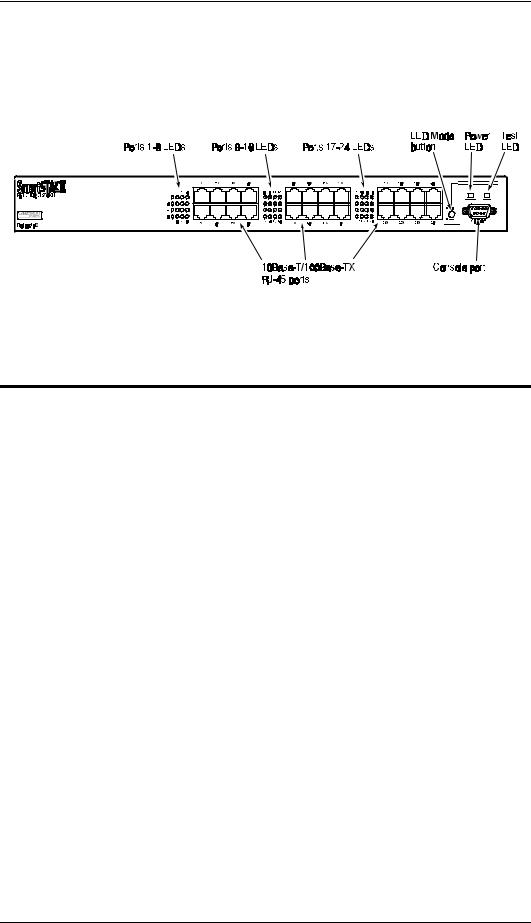
Figure 1-1 shows the front panel of the ELS100-24TX. Table 1-1 defines the ELS100-24TX front panel components.
Figure 1-1. ELS100-24TX Front Panel |
Table 1-1. Front Panel Components
Name |
Function |
Ports 1-24 LEDs |
Indicates Link, Activity, Speed and Duplex information (see |
|
Table 1-2 for details). |
10Base-T/100Base-TX |
RJ-45 connectors numerically identified based on the |
RJ-45 ports (Ports 1-24) |
specific product configuration. All ports are wired MDI-X. |
LED mode button |
Button used to switch port LEDs between Link/Activity mode |
|
and 100M/Full Duplex mode. |
Power LED |
Lights steady green to indicate power is supplied to the |
|
switch. Off indicates no power is supplied to the switch. |
Test LED |
Lights steady green after a reset and remains on until |
|
successful completion of power-on self tests. Off indicates a |
|
successful completion of the power-on self tests. |
Console port |
Female DB-9 connector configured as a null modem connec- |
|
tion for serial out-of-band management using the console |
|
menus. |
|
|
9032579-03 |
Product Overview 3 |

Figure 1-2 shows the Link and Activity port LEDs for 24 10Base-T/ 100Base-TX ports (default configuration). Pressing the front panel LED mode button changes the operation of these LEDs to 100M Speed and Full Duplex, as shown in Figure 1-3.
The numbers above and below the port LEDs identify the
LEDs associated with a specific RJ-45 port.
The port LEDs are grouped to the left of their corresponding RJ-45 ports. Table 1-2 defines the performance of the port LEDs for the 10Base-T/ 100Base-TX ports in both the default configuration and with the LED mode button pressed.
1 |
2 |
3 |
4 |
9 |
10 |
11 |
12 |
17 |
18 |
19 |
20 |
Link |
|
|
|
Link |
|
|
|
Link |
|
|
|
Activity |
|
|
|
Activity |
|
|
|
Activity |
|
|
|
Link |
|
|
|
Link |
|
|
|
Link |
|
|
|
Activity |
|
|
|
Activity |
|
|
|
Activity |
|
|
|
5 |
6 |
7 |
8 |
13 |
14 |
15 |
16 |
21 |
22 |
23 |
24 |
Figure 1-2. Port LEDs Default Configuration
1 |
2 |
3 |
4 |
9 |
10 |
11 |
12 |
17 |
18 |
19 |
20 |
10/100 speed |
|
|
|
10/100 speed |
|
|
|
10/100 speed |
|
|
|
Full/half duplex |
|
|
|
Full/half duplex |
|
|
|
Full/half duplex |
|
|
|
10/100 speed |
|
|
|
10/100 speed |
|
|
|
10/100 speed |
|
|
|
Full/half duplex |
|
|
|
Full/half duplex |
|
|
|
Full/half duplex |
|
|
|
5 |
6 |
7 |
8 |
13 |
14 |
15 |
16 |
21 |
22 |
23 |
24 |
Figure 1-3. Port LEDs LED Mode Button Pressed
4 Product Overview |
ELS100-24TX |
|
Table 1-2. Port LEDs Defined |
|
|
Name |
Function |
|
|
Default |
Link LED On: Indicates a valid connection (link) on the |
Configuration |
associated port. |
|
Link LED Off: Indicates no link on the associated port. |
|
Activity LED flashing: Indicates the presence of transmit and/or |
|
receive activity. |
|
Activity LED Off: Indicates the absence of transmit or receive |
|
activity. |
LED mode button pressed
Speed LED On: Indicates the port is in the 100Base-TX mode. Speed LED Off: Indicates the port is in the 10Base-T mode. Duplex LED On: Indicates the port is in the full duplex mode. Duplex LED Off: Indicates the port is in the half duplex mode.
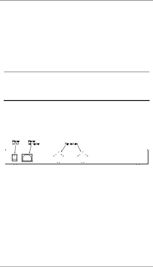
Rear Panel
Figure 1-4 shows the ELS100-24TX rear panel and Table 1-3 defines the rear panel components.
|
|
|
|
|
|
|
|
|
|
|
|
|
|
|
|
|
|
|
|
|
|
|
|
|
|
|
|
|
|
|
|
|
|
|
|
|
|
|
|
|
|
|
|
|
|
|
|
|
|
|
|
|
|
|
|
|
|
|
|
|
|
|
|
|
|
|
|
|
|
|
|
|
|
|
|
|
|
|
|
|
|
|
|
|
|
|
|
|
|
|
|
|
|
|
|
|
|
|
|
|
|
|
|
|
|
|
|
|
|
|
|
|
|
|
|
|
|
|
|
|
|
|
|
|
|
|
|
|
|
|
|
|
|
|
|
|
|
|
|
|
|
|
|
|
|
|
|
|
|
|
|
|
|
|
|
|
|
|
|
|
|
|
|
|
|
|
|
|
|
|
|
|
|
|
|
|
|
|
|
|
|
|
|
|
|
|
|
|
|
|
|
|
|
|
|
|
|
|
Figure 1-4. ELS100-24TX Rear Panel |
|||||||||||||||||
|
|
|
|
|
|
|
|
|
|
|
|
|
Table 1-3. Rear Panel Components |
|||||||||||||||||
|
|
|
|
|
|
|
|
|
|
|
|
|
|
|
|
|
|
|
|
|
|
|
|
|
|
|
|
|
|
|
|
Name |
|
Function |
|||||||||||||||||||||||||||
|
|
|
|
|
|
|
|
|
|
|
|
|
|
|
|
|
|
|
|
|
|
|
|
|
|
|
|
|
|
|
|
Power Connector |
|
Provides AC power to the switch. |
|||||||||||||||||||||||||||
|
Power Switch |
|
Allows you to turn the switch power on and off. |
|||||||||||||||||||||||||||
|
Fan Outlets |
|
Air exit vents through which internal fans discharge air |
|||||||||||||||||||||||||||
|
|
|
|
|
|
|
|
|
|
|
|
|
|
for ventilation purposes. |
||||||||||||||||
|
|
|
|
|
|
|
|
|
|
|
|
|
|
|
|
|
|
|
|
|
|
|
|
|
|
|
|
|
|
|
9032579-03 |
Product Overview 5 |

Feature Summaries
The following summaries provide a brief description of ELS100-24TX features in areas such as standards compliance, functionality, performance, and options.
IEEE 802.1D Bridge
The ELS100-24TX switch is fully compliant with IEEE 802.1D transparent bridging specifications. An aggregate address table containing 4096 entries per 8 switch ports is provided for learning, filtering, and forwarding. The switch can support up to a maximum of 12,288 addresses. Addresses are automatically learned by the switch, and can be individually assigned specific forwarding treatment by the network administrator if desired. Forwarding table configuration can be made out- of-band via the console interface or in-band via SNMP or Telnet. Static and dynamic addresses are both stored in this table. One static address is assigned per port by default. The Forwarding Table Configuration screen in the console menus allows you to assign additional static addresses if required.
Spanning Tree Protocol
The ELS100-24TX switch supports the IEEE 802.1D Spanning Tree Protocol. This protocol allows redundant connections to be created between different LAN segments for purposes of fault tolerance. Two or more physical paths between different segments can be created through the switch, with the Spanning Tree Protocol choosing a single path at any given time and disabling all others. If the chosen path fails for any reason, a disabled alternative is activated, thereby maintaining the connection. This prevents network traffic from circulating in an endless loop formed by multiple connections to the same LAN segment.
Spanning Tree parameters are configurable in the Spanning Tree Configuration Menu using the console menus or via SNMP (see Appendix B, “Spanning Tree Concepts,” for more information).
Frame Buffering and Frame Latency
The ELS100-24TX switch is a store-and-forward switching device. Each frame is copied into switch memory before being forwarded to another port. This method ensures that all forwarded frames conform to a standard Ethernet frame size and have a correct cyclic redundancy check (CRC) for data integrity. This switching method prevents bad frames from traversing the network and using up valuable network bandwidth, as with cut-through switching technology.
To minimize the possibility of dropping frames on congested ports, the ELS100-24TX switch provides 4 MB of dynamically allocated frame buffering per 8 ports. This buffer space is used to queue packets for transmission on congested networks. This is an additional advantage over cut-through switching technology, which drops packets immediately when experiencing collisions.
6 Product Overview |
ELS100-24TX |
Software Download
The ELS100-24TX switch supports the industry-standard Trivial File Transfer Protocol (TFTP) for downloading software to the switch. All switch software is stored in a 2 MB sectored flash ROM. The download feature allows you to easily install software upgrades to the unit. Software can alternatively be downloaded via the serial console port using the XMODEM protocol.
A TFTP or XMODEM software download is invoked via the Download Software Menu using the console menus. A TFTP download can also be invoked via SNMP.
Non-volatile Parameter Storage
Important operating parameters such as IP addresses, Spanning Tree configuration, and management security parameters, are stored in nonvolatile Flash memory. These values are retained when the switch experiences power interruptions or is powered down for normal maintenance.
Configuration and Management Interfaces
The ELS100-24TX switch can be managed using any of the following three methods:
•Serial console, out-of-band
An RS-232 connection, using a DB-9 connector, is supported for out- of-band switch management. Serial console management is performed using a terminal, or computer system running communications software. See Chapter 3, “ELS100-24TX User Interface,” for more detailed information on managing the ELS100-24TX switch via the serial console.
•Telnet, in-band (over Ethernet)
The switch supports management through a Telnet connection using the TCP/IP protocols. Telnet is performed using an ASCII terminal or computer system running communications software. See Chapter 3, “ELS100-24TX User Interface,” for more detailed information on managing the switch via the serial console. Global password protection for changing the operating parameters of the switch is provided.
•SNMP-based network manager, in-band
The switch can be managed using SNMP, the most common protocol used today for network management. Standard agent MIBs embedded in the switch provide basic SNMP management through indus- try-standard SNMP applications.
Management security protection is provided based on SNMP community names. See Chapter 5, “SNMP Management,” for more information.
9032579-03 |
Product Overview 7 |

RMON
RMON (Remote Monitoring) is a facility used to manage networks remotely while providing multi-vendor interoperability between monitoring devices and management stations. RMON is defined by an SNMP MIB. This MIB is divided into nine different groups, each gathering specific statistical information or performing a specific function. RMON-capable devices gather network traffic data and then store them locally until downloaded to an SNMP management station.
The ELS100-24TX supports four of the nine groups of RMON defined for Ethernet networks on a per port basis. Specifically, these are:
•Statistics: a function that maintains counts of network traffic statistics such as number of packets, broadcasts, collisions, errors, and distribution of packet sizes.
•History: a function which collects historical statistics based on userdefined sampling intervals. The statistical information collected is the same as the Statistics group, except on a time stamped basis.
•Alarm: a function that allows managers to set alarm thresholds based on traffic statistics. Alarms trigger other actions through the Event group.
•Event: a function that operates with the Alarm group to define an action that will be taken when an alarm condition occurs. The event may write a log entry and/or send a trap message.
RMON Statistics group information is displayed on the Port Statistics Screen in the console menus. Additional RMON functionality is available via SNMP.
Port Mirroring
The ELS100-24TX switch includes the ability to mirror the traffic being switched on any port for purposes of network traffic analysis and connection integrity. When this feature is enabled, a protocol analyzer or RMON probe is connected to any port in a group of eight. This port is configured to mirror the traffic from any other port in the same group of ports. The groupings are ports 1-8, 9-16 and 17-24. You can only mirror one port to another port at one time. Port mirroring occurs at the same speed configured for the port (10Mbps-to-10Mbps or 100Mbps-to- 100Mbps). Port mirroring is configurable in the Switch Configuration Menu using the console menus or via SNMP.
Auto-negotiation
Auto-negotiation is a process that permits the switch to automatically select the operational modes of its ports. Upon first being connected, the switch detects the speed of the network the port is connected to, either 10Mbps or 100Mbps, and the type of communication setting, half or full duplex. The port is then automatically set by the switch to operate in the proper mode, without user intervention. It is not required that the network device being connected to the switch supports auto-negotiation as the
8 Product Overview |
ELS100-24TX |

ELS100-24TX switch automatically adjusts to the network device’s communication settings. Auto-negotiation is configurable in the Port Configuration Menu of the console menus or via SNMP.
Broadcast Throttling
The ELS100-24TX has the capability to throttle (or limit) the flooding of packets through the switch. Broadcast, multicast, and unknown destination address unicast packets received by the switch are typically flooded to all ports on the switch or on a given VLAN. When the number of these types of packets being forwarded is large, the performance of the switch in forwarding packets of other types may suffer. A programmable broadcast cutoff rate parameter allows a rate threshold to be set in the switch for the forwarding of broadcast and unknown destination address packets. If the cutoff rate is exceeded, further packets of these types are dropped. This capability helps to alleviate broadcast storms, a problem often encountered in Ethernet networks. Broadcast throttling is configurable in the Switch Configuration menu of the console menus or via SNMP.
BootP/DHCP
The Bootstrap Protocol (BootP) and the Dynamic Host Configuration Protocol (DHCP) provide for the capability of passing configuration information to hosts on a TCP/IP network. Using this process, network devices do not need to be configured before they can communicate using the TCP/IP protocol suite. The ELS100-24TX switch uses BootP and DHCP to automatically configure IP address information without requiring access to the console menus. BootP/DHCP operation is configurable using the BootP/DHCP Enable option in the System Configuration Menu of the console menus or via SNMP.
LEDs
The switch port LEDs provide a quick and accurate display of the integrity of switch connections and switch mode. The operation of the port LEDs can be changed by use of the LED mode button on the switch front panel. The default operation of the LEDs indicates Link (L) and Activity (A) for each of the ports. When the LED mode button is pressed (pressed and held in), the operation of the LEDs changes to indicate 10/100 Mbps speed and full/half duplex operation, respectively.
Full Duplex Mode
The full duplex mode of operation on a port can double the throughput of switch connections. This mode disables the collision detection portion of the Ethernet Carrier Sense Multiple Access with Collision Detection (CSMA/CD) protocol, allowing for two-way traffic. Full duplex is configurable using the Duplex Mode parameter in the Port Menu of the console menus or via SNMP.
9032579-03 |
Product Overview 9 |

Flow Control
Flow control allows you to manage network traffic during congestion periods and to prevent the loss of packets when port buffer thresholds are exceeded. Flow control also serves to deny access to additional traffic that could add to a congestion condition. The ELS100-24TX switch supports flow control per the IEEE 802.3x standard. See Appendix C, “Flow Control,” for more information on this feature.
Virtual LANs (VLANs)
VLANs allow you to connect users to a specific LAN segment regardless of their physical location. The ELS100-24TX switch supports tagged VLANs per the IEEE 802.1Q draft standard. With frame tagging, a short tag is appended to every frame that crosses the network backbone. The tag identifies which VLAN the frame belongs to. See Appendix D, “Virtual LANs,” for more information.
Class of Service
Class of Service support allows you to assign a higher priority to selected traffic passing through the switch. The ELS100-24TX switch supports Class of Service attributes per the IEEE 802.1p draft standard using a priority queuing mechanism. This feature ensures that traffic during congestion periods will not interfere with traffic assigned a higher priority. Traffic assigned a lower priority is subject to discard when memory is in short supply. See Appendix E, “Class of Service,” for more information.
Application Examples
The exploding popularity of the Internet and of corporate intranets, as well as new, high-bandwidth desktop applications, are driving the demand for Fast Ethernet. The increase in multimedia traffic and the need to support legacy protocols alongside new, data intensive applications is driving the need for network segmentation and traffic prioritization.
The ELS100-24TX switch is ideal for meeting the needs of today’s high performance networks. The switch’s low cost and high port count makes it attractive and affordable for dedicated 10/100Mbps connections to the desktop. In addition, extensive features, including redundant links, traffic Class of Service and VLAN capability, provide the management needed for the workgroup and local backbone.
The following sections illustrate the ELS100-24TX switch employed in application examples:
•Client/Server Network
•Local Backbone
10 Product Overview |
ELS100-24TX |
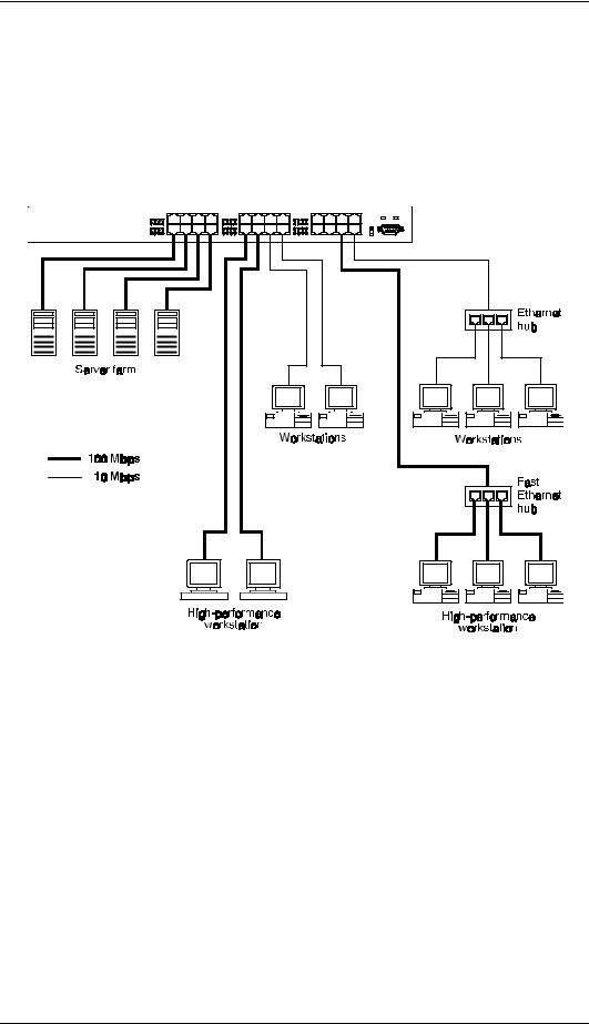
Client/Server Network Application
To improve workstation performance in a client/server environment, the ELS100-24TX switch can be configured to provide 200 Mbps full duplex Fast Ethernet connections to servers by connecting each to a dedicated switch port (Figure 1-5). Users can be accommodated through connections to hubs, both at 10Mbps and 100Mbps speeds, through 10Mbps switches with 100Mbps uplinks, or through direct connections.
Figure 1-5. |
Client/Server Network Application |
9032579-03 |
Product Overview 11 |

Local Backbone Application
The ELS100-24TX switch can be used in a local backbone application, connecting network segments together and providing file-server access (Figure 1-6). Workgroup hubs are provided with a single connection to the switch while servers are put on dedicated 100 Mbps ports. Routers and other networking devices can connect off of the switched backbone as well.
Figure 1-6. Local Backbone Application
12 Product Overview |
ELS100-24TX |

2. INSTALLATION
Inspecting Your Shipment
When you receive the shipment of your switch, check the package contents and make sure you have the following items:
•ELS100-24TX Ethernet switch
•Mounting ears and mounting screws
•Power cord
•This document
Site Requirements
Before you install the switch, make sure the site meets the following requirements:
•Mounting
Provide a flat table, wall or shelf surface, or an optional 19 in. (48.3 cm) equipment rack.
Use an EIA standard equipment rack that is grounded and physically secure.
•Power source
Provide a power source within six feet (1.8 m) of the installation location. This source must provide 100 VAC to 240 VAC, and 50 Hz to 60 Hz power, with a 100 VA minimum. Power specifications for the switch are shown in Appendix A, “Technical Specifications.”
Primary voltage selection within the above ranges is automatic and requires no user action.
•Environmental
Install the ELS100-24TX switch in a dry area, with adequate air circulation. Avoid placing the switch in direct sunlight or near other heat sources, such as hot-air vents. For temperature and humidity specifications, see Appendix A, “Technical Specifications.”
•Ventilation
Do not restrict airflow by covering or obstructing air inlets on the side of the switch or the rear panel internal air fan exits.
9032579-03 |
Installation 13 |

Mounting the Switch on a Table or Shelf
Mount the switch on a table or shelf in a position which allows access to the front panel RJ-45 ports, visibility of the port LEDs, and access to the power connector. Make sure that the mounting surface can safely support the switch and that there is adequate space around the switch for ventilation and cooling.
14 Installation |
ELS100-24TX |
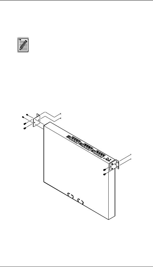
Mounting the Switch on a Wall
The switch ships with two (2) multi-position mounting ears and four (4) mounting screws.
The mounting screws are used to attach the mounting ears to the switch. Once the ears are attached to the switch, you will need to provide appropriate screws to mount the switch to the wall.
Figure 2-1 shows the orientation of the mounting ears for attaching the ears to the switch for a wall mount application. Be sure that the wall surface can safely support the switch.
Do the following:
1.Mount one of the ears to the switch using two (2) of the supplied screws. Repeat this step for the other side of the switch.
2.Mount the switch to the wall using appropriate screws.
Figure 2-1. Mounting the Switch on a Wall
9032579-03 |
Installation 15 |
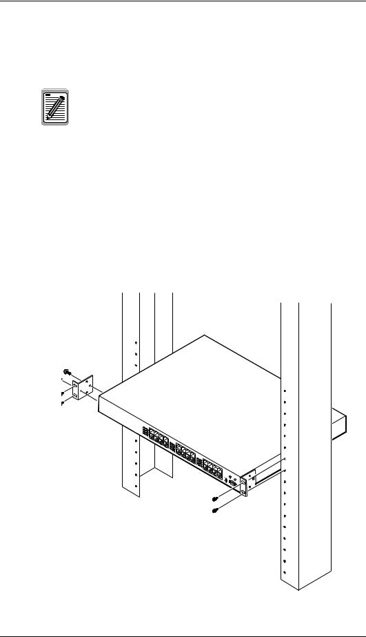
Mounting the Switch in a Rack
The switch ships with two (2) multi-position mounting ears and four (4) mounting screws.
The mounting screws are used to attach the mounting ears to the switch. Once the ears are attached to the switch, you will need to provide appropriate screws to mount the switch in a rack.
Figure 2-2 shows the orientation of the mounting ears for attaching the ears to the switch for a rack mount application. Mount the switch with the front panel facing forward. Do the following:
1.Mount one of the ears to the switch using two (2) of the supplied screws. Repeat this step for the other side of the switch.
2.Slide the switch into the rack and align the holes in the rack mounting ears with the holes in the rack rails.
3.Insert and tighten appropriate rack-mounting screws (not provided
Figure 2-2. Mounting the Switch in a Rack
16 Installation |
ELS100-24TX |
 Loading...