


ULTRA-1
ULTRA-2
SERVICE & REPAIR MANUAL
BUNN-O-MATIC CORPORATION
POST OFFICE BOX 3227 SPRINGFIELD, ILLINOIS 62708-3227
PHONE: (217) 529-6601 FAX: (217) 529-6644
41084.0000D 03/13 ©2009 Bunn-O-Matic Corporation
BUNN-O-MATIC COMMERCIAL PRODUCT WARRANTY
Bunn-O-Matic Corp. (“BUNN”) warrants equipment manufactured by it as follows:
1)Airpots, thermal carafes, decanters, GPR servers, iced tea/coffee dispensers, MCP/MCA pod brewers thermal servers and Thermofresh servers (mechanical and digital)- 1 year parts and 1 year labor.
2)All other equipment - 2 years parts and 1 year labor plus added warranties as specified below:
a)Electronic circuit and/or control boards - parts and labor for 3 years.
b)Compressors on refrigeration equipment - 5 years parts and 1 year labor.
c)Grinding burrs on coffee grinding equipment to grind coffee to meet original factory screen sieve analysis - parts and labor for 4 years or 40,000 pounds of coffee, whichever comes first.
These warranty periods run from the date of installation BUNN warrants that the equipment manufactured by it will be commercially free of defects in material and workmanship existing at the time of manufacture and appearing within the applicable warranty period. This warranty does not apply to any equipment, component or part that was not manufactured by BUNN or that, in BUNN’s judgment, has been affected by misuse, neglect, alteration, improper installation or operation, improper maintenance or repair, non periodic cleaning and descaling, equipment failures related to poor water quality, damage or casualty. In addition, the warranty does not apply to replacement of items subject to normal use including but not limited to user replaceable parts such as seals and gaskets. This warranty is conditioned on the Buyer 1) giving BUNN prompt notice of any claim to be made under this warranty by telephone at (217) 529-6601 or by writing to Post Office Box 3227, Springfield, Illinois 62708-3227; 2) if requested by BUNN, shipping the defective equipment prepaid to an authorized BUNN service location; and 3) receiving prior authorization from BUNN that the defective equipment is under warranty.
THE FOREGOING WARRANTY IS EXCLUSIVE AND IS IN LIEU OF ANY OTHER WARRANTY, WRITTEN OR ORAL, EXPRESS OR IMPLIED, INCLUDING, BUT NOT LIMITED TO, ANY IMPLIED WARRANTY OF EITHER MERCHANTABILITY OR FITNESS FOR A PARTICULAR PURPOSE. The agents, dealers or employees of BUNN are not authorized to make modifications to this warranty or to make additional warranties that are binding on BUNN. Accordingly, statements by such individuals, whether oral or written, do not constitute warranties and should not be relied upon.
If BUNN determines in its sole discretion that the equipment does not conform to the warranty, BUNN, at its exclusive option while the equipment is under warranty, shall either 1) provide at no charge replacement parts and/or labor (during the applicable parts and labor warranty periods specified above) to repair the defective components, provided that this repair is done by a BUNN Authorized Service Representative; or 2) shall replace the equipment or refund the purchase price for the equipment.
THE BUYER’S REMEDY AGAINST BUNN FOR THE BREACH OF ANY OBLIGATION ARISING OUT OF THE SALE OF THIS EQUIPMENT, WHETHER DERIVED FROM WARRANTY OR OTHERWISE, SHALL BE LIMITED, AT BUNN’S SOLE OPTION AS SPECIFIED HEREIN, TO REPAIR, REPLACEMENT OR REFUND.
In no event shall BUNN be liable for any other damage or loss, including, but not limited to, lost profits, lost sales, loss of use of equipment, claims of Buyer’s customers, cost of capital, cost of down time, cost of substitute equipment, facilities or services, or any other special, incidental or consequential damages.
392, A Partner You Can Count On, Air Infusion, AutoPOD, AXIOM, BrewLOGIC, BrewMETER, Brew Better Not Bitter, BrewWISE, BrewWIZARD, BUNN Espress, BUNN Family Gourmet, BUNN Gourmet, BUNN Pour-O-Matic, BUNN, BUNN with the stylized red line, BUNNlink, Bunn-OMatic, Bunn-O-Matic, BUNNserve, BUNNSERVE with the stylized wrench design, Cool Froth, DBC, Dr. Brew stylized Dr. design, Dual, Easy Pour, EasyClear, EasyGard, FlavorGard, Gourmet Ice, Gourmet Juice, High Intensity, iMIX, Infusion Series, Intellisteam, My Café, Phase Brew, PowerLogic, Quality Beverage Equipment Worldwide, Respect Earth, Respect Earth with the stylized leaf and coffee cherry design, Safety-Fresh, savemycoffee.com, Scale-Pro, Silver Series, Single, Smart Funnel, Smart Hopper, SmartWAVE, Soft Heat, SplashGard, The Mark of Quality in Beverage Equipment Worldwide, ThermoFresh, Titan, trifecta, Velocity Brew, Air Brew, Beverage Bar Creator, Beverage Profit Calculator, Brew better, not bitter., BUNNSource, Coffee At Its Best, Cyclonic Heating System, Daypart, Digital Brewer Control, Element, Nothing Brews Like a BUNN, Pouring Profits, Signature Series, Tea At Its Best, The Horizontal Red Line, Ultra are either trademarks or registered trademarks of Bunn-O-Matic Corporation. The commercial trifecta® brewer housing configuration is a trademark of Bunn-O-Matic Corporation.
2 |
41084 021513 |
|
CONTENTS |
|
Warranty.................................................................................................................................... |
2 |
User Notices.............................................................................................................................. |
3 |
Site Preparation ........................................................................................................................ |
3 |
Introduction............................................................................................................................... |
4 |
Operating Controls.................................................................................................................... |
6 |
Preventive Maintenance |
|
Recommended Cleaning ..................................................................................................... |
8 |
Auto-fill Cleaning Instructions........................................................................................... |
10 |
Preventive Maintenance Schedule..................................................................................... |
11 |
Troubleshooting................................................................................................................. |
14 |
Service |
|
Access Panels.................................................................................................................... |
22 |
Auger Motors.................................................................................................................... |
23 |
Auger Motor Capacitors..................................................................................................... |
24 |
Auger Shaft Assembly....................................................................................................... |
25 |
Circuit Breaker................................................................................................................... |
27 |
Compressor ....................................................................................................... |
28,31,34,37 |
Relay (or Contactor on Early Models)................................................................................ |
39 |
Control Board.................................................................................................................... |
40 |
Cooling Drum Alignment................................................................................................... |
41 |
Fan................................................................................................................................ |
42,43 |
Hot Gas Sensor................................................................................................................. |
44 |
Lamp Cord Assembly........................................................................................................ |
45 |
Lamp Cord Connector....................................................................................................... |
46 |
Lamp Holder/Socket Assembly.......................................................................................... |
47 |
Lamp Relay........................................................................................................................ |
48 |
Membrane Switch......................................................................................................... |
49,50 |
Solenoids........................................................................................................................... |
51 |
Temperature Sensor Assembly.......................................................................................... |
52 |
Torque Sensor Circuit Board.............................................................................................. |
53 |
Transformer ...................................................................................................................... |
54 |
Coolant Schematics................................................................................................................. |
55 |
Electrical Schematics............................................................................................................... |
57 |
USER NOTICES
All notices on this equipment are written for your protection. All notices are to be kept in good condition. Replace any unreadable or damaged labels.
Site preparation
The dispenser must have at least four inches of space behind it. This space is needed for airflow, air filter removal, and cleaning. Minimal clearance is required between the dispenser sides and the wall or another appliance. The dispenser performs better if not placed near any heating appliance. Leave some space so the dispenser can be moved for cleaning.
3 |
41084 102709 |
|
INTRODUCTION
Safety first!
To avoid electrical shock, unplug dispenser from power source before servicing inside.
WARNING: When powered, the condenser cooling fan will turn on every 30 minutes to aid cooling the entire unit, even when not in the ICE or CHILL modes. KEEP HANDS AWAY FROM FAN!
Basic Maintenance
In order to maintain proper machine operation, the shaft seals and bushings need to be replaced as a Preventative Maintenance measure. A reminder message will appear every 6 months. Worn/dirty shaft seals/bushings will have a direct effect on torque sensing and prevent complete freezing in “ICE” mode.
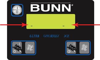
“UPPER” case vs “lower” case
Before beginning the process of troubleshooting, verify simple operating modes, ie; “CHILL” mode will not freeze the product, but “ICE” mode will. You should also observe the letter case size in either mode. UPPER case means the solenoid valve for that side is open, lower case, solenoid is closed.
|
JULY 4, 2002 |
|
|
Valve open |
ICE |
Ice |
Valve closed |
Fault codes
To aid in troubleshooting, fault codes are now incorporated into the display. See “Troubleshooting”.
4 |
41084 102709 |
|
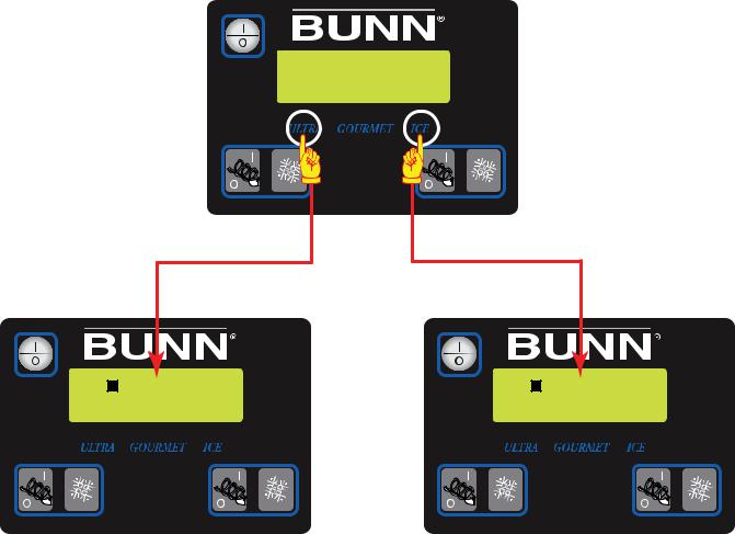
TEMP & TORQUE SCREEN
Press and hold for five seconds the ULTRA and ICE hidden switches to display the TEMP & TORQUE. The temperature of each cooling drum and the hot gas temperature will toggle back and forth. The auger torque is displayed continuously. Press and release the ULTRA and ICE hidden switches to return to HOME SCREEN. The TEMP & TORQUE mode is typically used for service.
DISPLAY
TEMP & TORQUE
30 |
25- |
30 |
25- |
161 |
161°h |
27 |
28°b |
NOTICE: While in the TEMP & TORQUE screen, the UPPER/lower case will be replaced by symbols. The 
 indicates the solenoid valve is open, and the
 indicates that solenoid is closed.
5 |
41084 102709 |
|
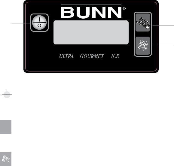
OPERATING CONTROLS
ULTRA-1
There are three of these switches that will be used for the operation of the dispenser.
1 |
2 |
|
3
P3932
1. switch (upper left corner of the control pad)
This switch is the ON/OFF toggle switch which powers up the dispenser and the LCD display. When ON
the Date and Time toggle back and forth continously except during programming.
2.  (upper right corner)
This is used to turn the auger motor to AUGER ON, AUGER OFF or AUGER REFILL ON. (Refill only applicable when installed) (See *NOTE)
3. (lower right corner)
This is used to turn the ice control to OFF, ICE or CHILL.
*NOTE: Refill system includes a “Maximum Fill Time” in the software. If the time to fill the hopper exceeds this limit, the hopper lights will flash and a “Refill Fault” will be displayed on the screen. If this accurs, check the product supply to ensure the BIB is not empty. (Change BIB if empty). Then press the “ULTRA” button for 3 seconds to clear the fault and restart the refill system.
6 |
41084 102709 |
|
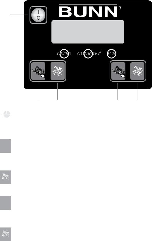
OPERATING CONTROLS
ULTRA-2
There are five of these switches that will be used for the operation of the dispenser.
1
P3677
2 |
3 |
4 |
5 |
1. switch (upper left corner of the control pad)
This switch is the ON/OFF toggle switch which powers up the dispenser and the LCD display. When ON
the Date and Time toggle back and forth continously except during programming.
2.  (bottom left corner)
This is used to turn the left side auger motor to AUGER ON, AUGER OFF or AUGER REFILL ON. (Refill only applicable when installed) (See *NOTE)
3. (bottom left corner)
This is used to turn the left side ice control to OFF, ICE or CHILL.
4. (bottom right corner)
This is used to turn the right side auger motor AUGER ON, AUGER OFF or AUGER REFILL ON. (Refill only
applicable when installed) (See *NOTE)
5. (bottom right corner)
This is used to turn the right side ice control to OFF, ICE or CHILL.
7 |
41084 102709 |
|
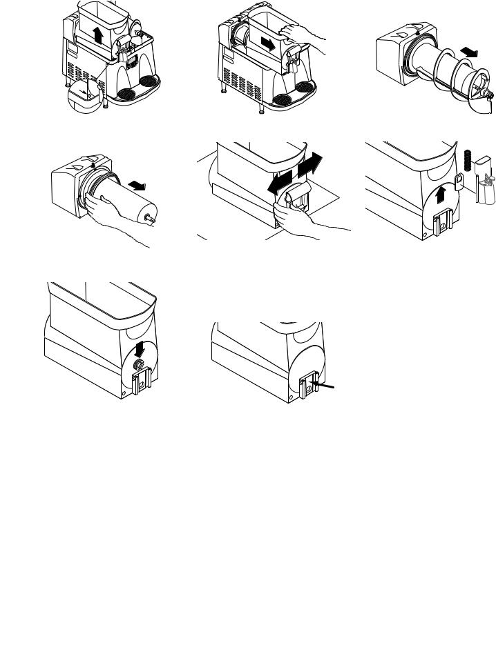
RECOMMENDED DAILY CLEANING (ULTRA-2 shown)
NOTE – Turn the power OFF to the dispenser before proceeding.
1.Empty all product from the hopper(s). Disconnect the hopper lid lamp cord(s) and remove the lids.
2. Depress the hopper lock plung- 3. Pull forward to remove. |
4. Pull the auger from the cooling |
er. Lift the hopper up slightly. |
drum. |
5. Remove the cooling drum seal 6. |
Caution: The faucet valve is 7. |
Carefully slide the faucet valve |
from the rear of the drum. |
under spring tension. Spread |
up to remove the spring and |
|
one side of the handle first, then |
faucet seal. Extra care should |
|
the other and disconnect from |
be taken when handling the |
|
the hopper. |
seal to prevent damage. Do not |
|
|
fold the seal as this will cause |
|
|
damage to the Teflon® sealing |
|
|
surface. |
8. Remove the auger nose bush- 9. |
Care must be taken to ensure this surface does not get scratched dur- |
ing from inside the hopper. |
ing cleaning. Deep scratches could cause leakage around the seal. |
10.Place all parts in a clean sink with mild hot water (120°F) and sanitizer solution. Allow all parts to soak for at least 5 minutes. Carefully wash all components with a clean wash cloth in the hot water and sanitizer solution. Use a clean, soft bristle brush as needed for the smaller components and tight areas. Do not immerse hopper lids. Use a commercial sanitizer that has 100 ppm of available chlorine with a concentration level of at least 3% available chlorine (KAY-5 Sanitizer). Follow the sanitizer’s mixing instructions to ensure 100 ppm of available chlorine.
11.Wash the drums, hopper drip trays, top covers, and outer enclosure using a clean wash cloth that has been dampened in the hot water and sanitizer solution. Pay particular attention to the shaft area and make sure it is thoroughly cleaned and sanitized.
12.Thoroughly rinse all surfaces with a clean wash cloth that has been dampened with hot water. Wipe dry with a clean dry wash cloth before reassembling the dispenser.
NOTE – Although most parts are dishwasher safe, they may be affected by the chemicals in some commercial sanitizing agents. Do not place the hopper nor hopper lids in a dishwasher. Rinse thoroughly before assembly.
8 |
41084 102709 |
|
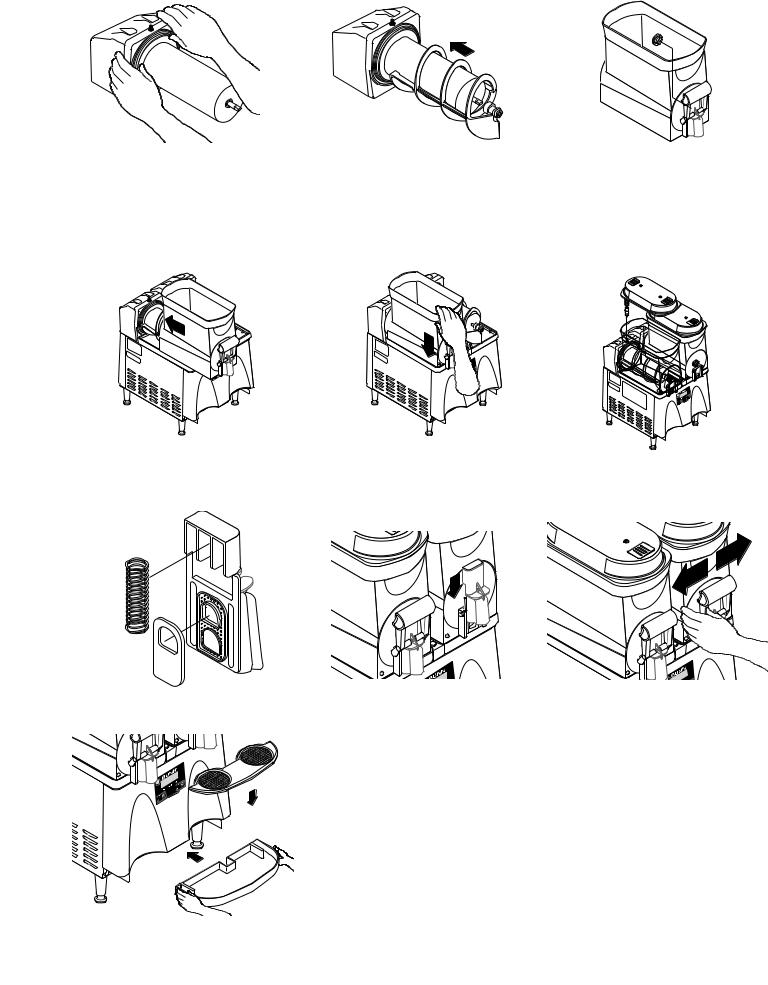
RECOMMENDED DAILY CLEANING (Continued)
1. Install the seal(s) over the 2. |
Align the auger shaft(s) with the 3. |
Install auger nose bushing into |
flange at the rear of the cooling |
auger(s). Push the auger(s) as |
inside front of hopper. |
drum(s) and press the seal(s) |
far as they will go and rotate so |
|
firmly into place as shown. |
the flat face of the auger shaft |
|
|
is aligned with the flat face of |
|
|
the auger nose. |
|
4. Thoroughly rinse the hopper(s) 5. |
Slide into place and push down 6. |
Set the lids on the hopper(s) |
and install over the auger(s) |
until the hopper lock plunger(s) |
and plug in the hopper lid lamp |
and cooling drum(s). |
snap into place. |
cord(s). |
7.Position the faucet seal and return spring in the faucet valve.
8.Slide the faucet valve assembly 9. Press down on the valve to
into place on the hopper. |
compress the spring. Position |
|
the faucet handle over the fau- |
|
cet valve one side at a time and |
|
snap into place on the hopper. |
10. Assemble the drip tray.
9 |
41084 102709 |
|
Auto-fill Cleaning Instructions
(With Brixing Pump Installed)
Materials required
1.Non-sudsing liquid detergent (such as common household automatic dishwasher liquid detergent).
2.Household bleach (Sodium chloride solution: 5.25%) or equivalent.
3.Clean five (5) gallon bucket.
4.Measuring Cup
5.An adaptor is needed to hold the Q.C.D. (Quick Connect/Disconnect) fitting on the concentrate suction line open. A connector from an empty bag will work.
Sanitizing Procedure
1.Fill bucket with 4 gallons of warm water (120-180 deg. F).
2.Measure 4 ounces (1/2 cup) of the liquid detergent and add to the water.
3.Measure 2 ounces (1/4 cup) of bleach and add to the water, then stir, mixing evenly.
4.Ensure that the refill for the Ultra hopper is turned off.
5.Empty all product from the Ultra hopper
6.Disconnect the concentrate line from the B-I-B and install adaptor on the quick disconnect so the line is open to the sanitizing solution. Place concentrate inlet line into the bucket so that the Q.C.D. will stay at the bottom.
7.Press the auger button to turn on the “Auger Refill On” feature.
8.Allow system to run until the hopper is about 1/4 full then turn off refill.
9.Switch three way sanitize valve to the Sanitize postion.
10.Turn refill system back on and let run until the hopper is almost full then turn off refill.
11.Allow sanitizer to sit in system for 10 minutes.
12.Drain sanitizer from hopper and remove the Q.C.D. from the sanitizer bucket.
13.Empty remaining sanitizer and refill bucket with about 2 gallons of warm (120-180 deg. F) rinse water.
14.Turn sanitize valve back to dispense position.
15.Place Q.C.D. into rinse water and turn on refill system.
16.Run until hopper is about 1/4 full.
17.Turn off refill system and drain hoppers.
18.Refer to the Recommended Daily Cleaning instructions and follow these steps to clean the hopper, lid and other dispense parts.
10 |
41084 040110 |
|
PREVENTIVE MAINTENANCE
A common problem occurs when the proper preventive maintenance procedures are not followed. Failure to perform these procedures may result in damaged equipment and may not be covered by warranty.
Please check the following items before assuming a refrigeration fault.
When the product does not freeze, there are several possibilities other than a failure in the refrigeration system. The torque between the auger motor and the frozen product is contolled by the torque sensor board measuring the distance between the pins on the coupler and shaft. When the distance between the pins reaches the maximum allowable distance, the compressor shuts off. The machine thinks the product thickness has reach the maximum and shuts off the compressor. The illustration below shows some of the other possible causes for a false reading from the torque sensor board.
Proper inspection and preventive maintenance (including daily cleaning) will avoid expensive repairs and costly down time.
NORMAL OPERATION
A
B
C
D
E
CHILL MODE |
ICE MODE |
A.MOTOR SHAFT TORQUE SENSOR PIN
B.AUGER SHAFT TORQUE SENSOR PIN
C.TORSION SPRINGS
D.AUGER SHAFT
E.AUGER MOTOR COUPLING
POSSIBLE CAUSES FOR FALSE READINGS
|
|
|
|
|
|
|
|
|
|
|
|
|
|
|
|
|
|
|
|
|
|
|
|
|
|
|
|
|
|
WEAK TORSION SPRINGS |
TOO MUCH KRYTOX GREASE |
||||||||
DAMAGED/CORRODED AUGER SHAFT |
|
|
|
|
|
||||
DAMAGED/WORN BUSHINGS/SEALS |
|
|
|
|
|
||||
|
|
|
|
|
|
|
|
|
|
|
|
|
|
|
|
|
|
|
|
|
|
|
|
|
|
|
|
|
|
|
|
|
|
|
|
|
|
|
|
BENT TORQUE SENSOR PINS |
MISSING TORQUE SENSOR PINS |
DIRTY OR DAMAGED TORQUE SENSOR BOARD
11 |
41084 102709 |
|
REQUIRED REGULAR MAINTENANCE: Semi Annual:
Bunn Kit #34245.0002 is required for ULTRA-1 and #34245.0000 & #34245.0001 is required for ULTRA-2, to perform the semi annual Preventive maintenance:
Note: Service caused by failure to perform required maintenance is not covered by warranty.
The following instructions apply to one hopper only; repeat each step for all hoppers.
Kit Contents
Inventory this kit for completeness before proceeding.
* 34245.0003 PM Kit, ULTRA-2 PAF w/ LEDs ** 34245.0001 PM Kit, ULTRA-2
***34245.0002 PM Kit, ULTRA-1
Part Number |
|
Qty. |
|
Description |
|
* |
** *** |
|
|
26781.0000 |
2 |
3 |
1 |
Auger Shaft Bushing (Blue) |
37593.0000 |
2 |
3 |
1 |
Cooling Drum Seal |
32079.0000 |
2 |
3 |
1 |
Hopper/Drum Seal |
32268.1000 |
2 |
3 |
1 |
Seal Kit, Faucet (Clear) |
29563.0000 |
- |
- |
- |
Lubricant (“Krytox”) |
28395.0000 |
1 |
1 |
1 |
Seal Insertion Tool |
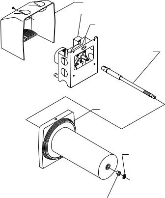
INSTRUCTIONS
Auger Motor Cover
Run Capacitor
Auger Motor Assy
Auger Shaft Assy
Hopper/Drum Seal
Cooling Drum
Seal
Cooling Drum 
Auger Shaft Bushing |
|
P2528 |
|
FIG 1
WARNING Disconnect the dispenser from the power source before the removal of any panel or the replacement of any component.
1.Drain, remove and clean hopper; refer to the Recommended Daily Cleaning instructions for proper cleaning procedures. Discard the hopper/drum seal and faucet seal.
2.Remove the #8 locking screws securing auger motor cover to the cooling drum mount assembly; remove cover and set aside for reassembly.
3.Remove the #8 locking screw on the lower right side (viewed from front) of the auger motor mounting bracket securing the auger motor run capacitor. Set capacitor aside with wires attached.
4.Disconnect the auger motor terminal from the terminal on the main wiring harness.
5.Remove the remaining #8 locking screws securing the cooling drum mounting bracket. Remove motor with mounting bracket.
NOTE: When removing or installing motor and shaft assembies, be sure the motor and shaft pins are turned to a position that will clear the torque sensor circuit board.
12 |
41084 052112 |
|
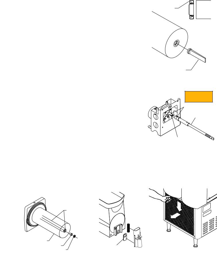
REQUIRED REGULAR MAINTENANCE (Continued)
6.Pull the auger shaft assembly straight out of cooling drum. Inspect the shaft for abnormal wear.
7.From the front of dispenser, remove the seal and blue bushing from cooling drum and discard them.
8.Inspect inside of the coling drum from the rear for product leakage and clean thoroughly with an extended bristle brush (Bunn part no. 40500.1068) and warm sanitize solution, rinse and dry with a towel. Clean the front seal/bushing area of the cooling drum thoroughly with the bristle brush. Refer to Fig. 4 for areas to be cleaned.
9.Refer to FIG 1, and slip new blue bushing into cooling drum.
10.Place seal on insertion tool #28395.0000 as shown in FIG 2. Make sure open face of seal is toward cooling drum.
11.Apply a small amount of food grade lubricant (Bunn #M2568.1001) to inside diameter of seal. Push seal into bore until it is firmly seated; remove tool.
12.Place a small amount of #29563.0000 “Krytox” lubricant (provided in kit in a plastic cap) on the end of the motor shaft
(about 1 1/2”) and a thin film in the groove. Install auger shaft assembly onto the motor shaft. See FIG 3. Do not use too much “Krytox” lubricant. Dirt or grease on pins will cause “optical” misreading by torque sensors.
NOTE: This is the only place “Krytox” lubricant is used.
13.Assemble motor/shaft assembly as shown in FIG 3, then install assembly into cooling drum. Make sure the pins do not hit the sensor board and cooling drum seal is not dislodged as the shaft passes through.
14.Secure motor and capacitor to the cooling drum mounting bracket. Install rear motor cover.
15.Refer to the hopper assembly and installation procedures. Install new hopper/drum seals and faucet seals included in the kit. See FIG 1 & 5.
16.Remove and clean condenser air filter. See FIG 6.
17.Refer to the Programming Manual, “Menu Function Index”. Scroll to menu “PM Complete?” and answer “YES” to reset the reminder message “PM Due”.
Open face of seal away from tool
Cooling Drum Seal 

Seal Insertion Tool
P1760
FIG 2
Check for weak torsion springs
Pins
Auger Shaft Assy
Lube about 1 1/2” of shaft and in the groove with #29563.0000 “Krytox” Lubricant
P2529
FIG 3
 Hopper/Drum Seal
Inspect & Clean
Cooling Drum |
|
|
|
|
Auger Shaft Bushing |
Faucet Seal |
|
|
|
Cooling Drum Seal |
|
P3695 |
P3682 |
|
FIG 4 |
FIG 5 |
FIG 6 |
||
|
||||
|
|
13 |
41084 052112 |
|
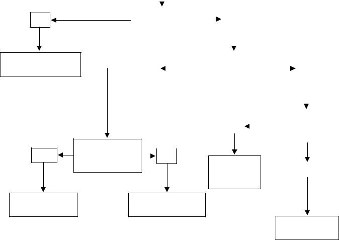
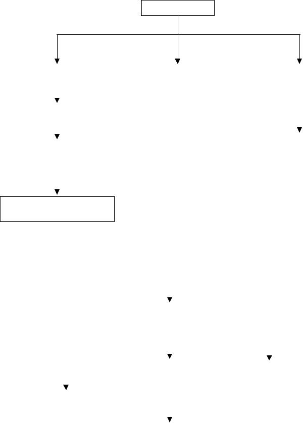
TROUBLESHOOTING
A troubleshooting guide is provided to suggest probable causes and remedies for the most likely problems encountered. If the problem remains after exhausting the troubleshooting steps, contact the Bunn-O-Matic Technical Service Department.
•Inspection, testing, and repair of electrical equipment should be performed only by qualified service personnel.
•All electronic components have 120 volt ac and/or low voltage dc potential on their terminals. Shorting of terminals or the application of external voltages may result in board failure.
•Intermittent operation of electronic circuit boards is unlikely. Board failure will normally be permanent. If an intermittent condition is encountered, the cause will likely be a switch contact or a loose connection at a terminal or crimp.
•Keep away from combustibles.
WARNING – • Exercise extreme caution when servicing electrical equipment.
•Unplug the dispenser when servicing, except when electrical tests are specified.
•Follow recommended service procedures
•Replace all protective shields or safety notices
No
Call licensed electrician for repair
Yes
Replace Control
Board
|
No Power |
|
|
|
|
||
|
|
|
|
|
|
|
|
|
|
|
|
|
|
|
|
|
|
|
|
|
|
|
|
|
Correct voltage |
|
|
|
|
|
|
|
|
|
|
Yes |
|||
|
at outlet? |
|
|
|
|||
|
|
|
|
||||
|
|
|
|
|
|
||
|
|
|
|
|
|
|
|
|
|
|
|
|
|
|
|
|
|
|
|
12vac to Control Board |
|
|
|
|
|
Yes |
|
|
|
|
No |
||
|
|
|
at J5-8 & J5-20? |
|
|
|||
|
|
|
|
|
||||
|
|
|
|
|
|
|
|
|
|
|
|
|
|
|
|
|
|
|
|
|
|
|
|
|
|
|
|
|
|
|
|
|
|
|
|
|
|
|
12vac from secondary |
No |
|
|
|
|
|
of transformer? |
|
|
|
||
|
|
|
|
|
|
|
|
Does Membrane |
|
|||
No |
||||
|
|
|
||
Switch test ok? |
||||
|
||||
Replace |
Yes |
Transformer |
|
|
Replace Membrane
Switch
Check main
wiring harness
14 |
41084 102709 |
|
TROUBLESHOOTING (cont.) |
|
|
|
|
|
|
|
|
|
|
|
|
|
|
|
|
|
|
|
|
|
|
|
|
|
|
|
|||||||||||||||||||||||
|
|
|
|
|
|
|
|
|
|
|
|
|
|
|
|
|
|
|
|
|
|
|
|
|
|
|
|
|
|
|
|
|
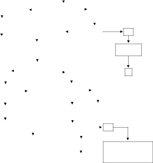
|
|
|
|
|
|
|
|
|
|
|
|
|
|
|
|
|
|
|
|
|
|
|
|
|
|
|
|
|
|
|
|
|
|
|
|
|
|
|
|
|
|
|
|
Chills but |
|
|
|
|
|
|
|
|
|
|
|
|
|
|||||||||||
|
|
|
|
|
|
|
|
|
|
|
|
|
|
|
|
|
|
|
|
|
|
|
|
|
won’t freeze |
|
|
|
|
|
|
|
|
|
|
|
|
|
||||||||||||
|
|
|
|
|
|
|
|
|
|
|
|
|
|
|
|
|
|
|
|
|
|
|
|
|
|
|
|
|
|
|
|
|
|
|
|
|
|
|
|
|
|
|
|
|
|
|
|
|
|
|
|
|
|
|
|
|
|
|
|
|
|
|
|
|
|
|
|
|
|
|
|
|
|
|
|
|
|
|
|
|
|
|
|
|
|
|
|
|
|
|
|
|
|
|
|
|
|
|
|
|
|
|
|
|
|
|
|
|
|
|
|
|
|
|
|
|
|
|
|
|
|
|
|
|
|
|
|
|
|
|
|
|
|
|
|
|
|
|
|
|
|
|
|
|
|
|
|
|
|
|
|
|
|
|
|
|
|
|
|
|
|
|
|
|
|
|
|
|
|
|
|
|
|
|
|
|
|
Dispenser in |
|
|
|
|
|
|
|
|
|
|
|
|
|
||||||||||||
|
|
|
|
|
|
|
|
|
|
|
|
|
No |
|
|
|
|
|
|
|
|
|
|
|
|
|
Yes |
|
|
|
||||||||||||||||||||
|
|
|
|
|
|
|
|
|
|
|
|
|
|
|
|
|
|
|
|
“DAY” mode? |
|
|
|
|
|
|
|
|
|
|||||||||||||||||||||
|
|
|
|
|
|
|
|
|
|
|
|
|
|
|
|
|
|
|
|
|
|
|
|
|
|
|
|
|
|
|
|
|
|
|
|
|
||||||||||||||
|
|
|
|
|
|
|
|
|
|
|
|
|
|
|
|
|
|
|
|
|
|
|
|
|
|
|
|
|
|
|
|
|
|
|
|
|
|
|
|
|
|
|
|
|
|
|
|
|
|
|
|
|
|
|
|
|
|
|
|
|
|
|
|
|
|
|
|
|
|
|
|
|
|
|
|
|
|
|
|
|
|
|
|
|
|
|
|
|
|
|
|
|
|
|
|
|
|
|
|
|
|
|
|
Set into |
|
|
|
|
|
|
|
|
|
|
|
|
|
|
|
|
|
|
|
|
|
|
|
|
|
|
|
|
|
|
|
|
|
|
|
|
|
|
|
|
|
|||||||
|
|
|
|
|
|
|
|
|
|
|
|
|
|
|
|
|
|
|
|
|
|
|
|
|
|
|
|
|
|
|
|
|
|
|
|
|
|
|
|
|
||||||||||
|
|
“DAY” mode |
|
|
|
|
|
|
|
|
|
|
|
|
|
|
|
|
|
|
|
|
|
|
|
|
|
|
|
|
|
|
|
|
|
|
|
|
|
|
|
|||||||||
|
|
|
|
|
|
|
|
|
|
|
|
|
|
|
|
|
|
|
|
|
|
|
|
|
|
|
Dispenser in |
|
|
|
||||||||||||||||||||
|
|
|
|
|
|
|
|
|
|
|
|
|
|
|
|
|
|
|
|
|
|
|
|
|
|
Yes |
|
|
|
|
|
|
|
|
|
|
||||||||||||||
|
|
|
|
|
|
|
|
|
|
|
|
|
|
|
|
|
|
|
|
|
|
|
|
|
|
|
|
|
|
|
|
|
“ICE” mode? |
|
|
|
||||||||||||||
|
|
|
|
|
|
|
|
|
|
|
|
|
|
|
|
|
|
|
|
|
|
|
|
|
|
|
|
|
|
|
|
|
|
|
|
|
|
|
|
|
||||||||||
|
|
|
|
|
|
|
|
|
|
|
|
|
|
|
|
|
|
|
|
|
|
|
|
|
|
|
|
|
|
|
|
|
|
|
|
|
|
|
|
|
||||||||||
|
|
|
|
|
|
|
|
|
|
|
|
|
|
|
|
|
|
|
|
|
|
|
|
|
|
|
|
|
|
|
|
|
|
|
|
|
|
|
|
|
|
|
|
|
|
|
|
|
|
|
|
|
1 |
|
|
|
|
|
|
|
|
|
|
|
|
|
|
|
|
|
|
|
|
|
|
|
|
|
|
|
|
|
|
|
|
|
|
|
|
|
|
|
|
|
|
|
|
||||
|
|
|
|
|
|
|
|
|
|
|
|
|
|
|
|
|
|
|
|
|
|
|
|
|
|
|
|
|
|
|
|
|
|
|
|
|
|
|
|
|
||||||||||
|
|
|
|
|
|
|
|
|
|
|
|
|
|
|
|
|
|
|
|
|
|
|
|
|
|
|
|
|
|
|
|
|
|
|
|
|
|
|
|
|
|
|
|
|
|
|
|
|||
|
|
|
|
|
|
|
|
|
|
|
|
|
|
|
|
Verify augers |
|
|
|
|
|
|
|
|
|
|
|
|
|
|
|
|
|
|
|
|
|
|
|
|
|
|
|
|||||||
|
|
|
|
|
|
|
|
|
|
|
|
|
|
|
|
|
|
|
|
|
|
|
|
|
|
|
|
|
|
|
|
|
|
|
|
|
|
|
|
|
|
|
||||||||
|
|
|
|
|
|
|
|
|
|
|
|
|
|
|
|
are turned on |
|
|
|
|
|
|
|
|
|
|
|
|
|
|
|
|
|
|
|
|
|
|
|
|
|
|
|
|||||||
|
|
|
|
|
|
|
|
|
|
|
|
|
|
|
|
|
|
|
|
|
|
|
|
|
|
|
|
|
|
|
|
|
|
|
|
|
|
|
|
|
|
|
|
|
|
|
||||
|
|
|
|
|
|
|
|
|
|
|
|
|
|
|
|
|
|
|
|
|
|
|
|
|
|
|
|
|
|
|
|
|
|
|
|
|
|
|
|
|
|
|
|
|
|
|
|
|
|
|
|
|
|
|
|
|
|
|
|
|
|
|
|
|
|
|
|
|
|
|
|
|
|
|
|
|
|
|
|
|
|
|
|
|
|
|
|
|
|
|
|
|
|
|
|
|
|
||||
|
|
|
|
|
|
|
|
|
|
|
|
|
|
|
Is display showing |
|
|
|
|
|
|
|
|
|
|
|
|
|
|
|
|
|
|
|
|
|
|
|
|
|
|
|
||||||||
|
|
|
|
|
|
No |
|
|
|
|
|
|
UPPER CASE |
|
|
|
|
|
|
|
|
|
|
Yes |
|
|
|
|
|
|
|
|
|
|
|
|
|
|||||||||||||
|
|
|
|
|
|
|
|
|
|
|
|
|
|
|
|
|
|
|
|
|
|
|
|
|
|
|
|
|
|
|
|
|
|
|||||||||||||||||
|
|
|
|
|
|
|
|
|
|
|
|
|
|
|
|
|
|
|
|
|
|
|
|
|
|
|
|
|
|
|
|
|
|
|||||||||||||||||
|
|
|
|
|
|
|
|
|
|
|
|
|
|
|
|
“ICE” mode? |
|
|
|
|
|
|
|
|
|
|
|
|
|
|
|
|
|
|
|
|
|
|
|
|
|
|
|
|||||||
|
|
|
|
|
|
|
|
|
|
|
|
|
|
|
|
|
|
|
|
|
|
|
|
|
|
|
|
|
|
|
|
|
|
|
|
|
|
|
|
|
|
|||||||||
|
|
|
|
|
|
|
|
|
|
|
|
|
|
|
|
|
|
|
|
|
|
|
|
|
|
|
|
|
|
|
|
|
|
|
|
|
|
|
|
|
|
|
|
|
|
|
||||
|
|
|
|
|
|
|
|
|
|
|
|
|
|
|
|
|
|
|
|
|
|
|
|
|
|
|
|
|
|
|
|
|
|
|
|
|
|
|
|
|
|
|
|
|
|
|
|
|
|
|
|
|
Is Thickness |
|
|
|
|
|
|
|
|
|
|
|
|
|
|
|
|
|
|
|
Is Brix |
|
|
|
|
|
|
|
|
|
|
|
|
|
|||||||||||||||
|
|
|
|
|
|
No |
|
|
|
|
|
|
|
|
|
|
|
|
|
|
|
|
|
|
Yes |
|
|
|
||||||||||||||||||||||
|
|
screen set low? |
|
|
|
|
|
|
|
|
|
|
|
|
|
level high? |
|
|
|
|
|
|
|
|||||||||||||||||||||||||||
|
|
|
|
|
|
|
|
|
|
|
|
|
|
|
|
|
|
|
|
|
|
|||||||||||||||||||||||||||||
|
|
|
|
|
|
|
|
|
|
|
|
|
|
|
|
|
|
|
|
|
|
|
|
|
|
|
|
|
||||||||||||||||||||||
|
|
|
|
|
|
|
|
|
|
|
|
|
|
|
|
|
|
|
|
|
|
|
|
|
|
|
|
|
|
|
|
|
|
|
|
|
|
|
|
|
|
|
|
|
|
|
|
|
|
|
|
|
|
|
|
|
|
|
|
|
|
|
|
|
|
|
|
|
|
|
|
|
|
|
|
|
|
|
|
|
|
|
|
|
|
|
|
|
|
|
|
|
|
|
|
|
|
|
|
|
|
|
|
|
|
|
|
|
|
|
|
|
|
|
|
|
|
|
|
|
|
|
|
|
|
|
|
|
|
|
|
|
|
|
|
|
|
|
|
|
|
|
|
|
|
|
|
|
|
|
|
|
|
|
|
|
|
|
|
|
|
|
|
|
|
|
|
|
|
|
|
|
|
|
|
|
|
|
|
|
|
|
|
|
|
|
|
|
|
|
|
|
|
|
|
|
|
2 |
|
|
|
|
|
|
|
|
|
|
|
Yes |
|
|
|
|
|
|
|
|
|
|
|
|
|
|
|
|
|
|
|
|
|
|
|
|
No |
|
|
|
|
|
|
|
|
|
|
|||||||||
|
|
|
|
|
|
|
|
|
|
|
|
|
|
|
|
|
|
|
|
|
|
|
|
|
|
|
|
|
|
|
|
|
|
|
|
|
|
|
|
|
|
|
||||||||
|
|
|
|
|
|
|
|
|
|
|
|
|
|
|
|
|
|
|
|
|
|
|
|
|
|
|
|
|
|
|
|
|
|
|
|
|
|
|
|
|
|
|
||||||||
|
|
|
|
|
|
|
|
|
|
|
|
|
|
|
|
|
|
|
|
|
|
|
|
|
|
|
|
|
|
|
|
|
|
|
|
|
|
|
|
|
|
|
|
|
|
|||||
|
|
|
|
|
|
|
|
|
|
|
|
|
|
|
|
|
|
|
|
|
|
|
|
|
|
|
|
|
|
|
|
|
|
|
|
|
|
|
|
|
|
|
|
|
|
|||||
|
|
|
|
|
|
|
|
|
|
|
|
|
|
|
|
|
|
|
|
|
|
|
|
|
|
|
|
|
|
|
|
|
|
|
|
|
|
|
|
|
|
|
|
|
||||||
|
|
|
|
|
|
|
|
|
|
|
|
|
|
|
|
|
|
|
|
|
|
|
|
|
|
|
|
|
|
|
|
|
|
|
|
|
|
|
|
|
|
|
|
|||||||
|
|
|
|
|
|
2 |
|
|
|
|
|
|
|
|
|
|
|
|
|
|
|
|
|
|
|
|
|
|
|
|
|
|
|
|
|
|
|
|
|
|
|
|
|
|
|
|
|
|
|
|
|
|
|
|
|
|
|
|
|
|
|
|
|
|
|
|
|
|
|
|
|
|
|
|
|
|
|
|
|
|
|
Is Filter dirty? |
|
|
|
|
|
|
|
||||||||||||
|
|
|
|
|
|
|
|
|
|
|
|
|
|
|
|
|
|
|
|
|
|
|
|
|
|
|
|
|
|
|
|
|
|
|
|
|
|
|
|
|
||||||||||
|
|
|
|
|
|
|
|
|
|
|
|
|
|
|
|
|
|
|
|
|
|
|
|
|
|
|
|
|
|
|
|
|
|
|
|
|
|
|
|
|
|
|
|
|
|
|
|
|
|
|
|
|
|
|
|
|
|
|
|
|
|
|
|
|
|
|
|
|
|
|
|
|
|
|
|
|
|
|
|
|
|
|
|
|
|
|
|
|
|
|
|
|
|
|
|
|
|
|
|
|
|
|
|
|
|
|
|
|
|
|
|
|
|
|
|
|
|
|
|
|
|
|
|
|
|
|
|
|||||||||||||||||||||||||
|
|
|
|
|
|
|
|
|
|
|
|
|
|
|
|
|
|
|
|
|
|
|
|
|
|
|||||||||||||||||||||||||
|
|
|
|
|
|
|
|
|
|
|
Inspect auger drive shafts |
|
|
|
|
|
|
|
|
|
|
|
|
|
|
|
|
|
|
|
|
|
|
|
||||||||||||||||
|
|
|
|
|
|
|
|
|
|
|
|
|
|
|
|
|
|
|
|
|
Yes |
|
|
|
|
|
|
|
|
|
||||||||||||||||||||
|
|
|
|
|
|
|
|
|
|
for weak torsion springs or |
|
|
|
|
|
|
|
|
|
|
|
|
|
|
|
|
|
|
||||||||||||||||||||||
|
|
|
|
|
|
|
|
|
|
|
|
|
|
|
|
|
|
|
|
|
|
|
|
|
||||||||||||||||||||||||||
|
|
|
|
|
|
|
|
|
|
damaged pins. Check for dirty |
|
|
|
|
|
|
|
|
|
|
|
|
|
|
|
|
|
|
|
|
|
|
|
|||||||||||||||||
|
|
|
|
|
|
|
|
|
|
|
|
|
|
|
|
|
|
|
|
|
|
|
|
|
|
|
|
|
|
|
|
|
||||||||||||||||||
|
|
|
|
|
|
|
|
|
|
or worn seals and bushings. |
|
|
|
|
|
|
|
|
|
|
|
|
|
|
||||||||||||||||||||||||||
|
|
|
|
|
|
|
|
|
|
|
|
|
|
|
|
|
|
|
|
3 |
|
|
|
|
|
|
|
|
|
|
||||||||||||||||||||
|
|
|
|
|
|
|
|
|
|
|
|
|
|
|
|
|
|
|
|
|
|
|
|
|
|
|
|
|
|
|
|
|
|
|
|
|
|
|
|
|
|
|
|
|
|
|
|
|||
|
|
|
|
|
|
|
|
|
|
|
|
|
|
|
|
|
|
|
|
|
|
|
|
|
|
|
|
|
|
|
|
|
|
|
|
|
|
|
|
|
|
|
|
|
|
|
|
|||
|
|
|
|
|
|
|
|
|
|
|
|
|
|
|
|
|
|
|
|
|
|
|
|
|
|
|
|
|
|
|
|
|
|
|
|
|
|
|
|
|
|
|
|
|
|
|
|
|
|
|
No
Set into “ICE” mode
1
No
Have a certified refrigeration technician check for low refrigerant or blockage.
1- Done |
|
2- Adjust |
|
3- Clean |
|
|
|
|
|
15 |
41084 102709 |
|
TROUBLESHOOTING (cont.)
No cooling at all
Yes
Set into “ICE” or “CHILL” mode
1
Yes
Plug directly inti outlet
1
No
Call a licensed electrician
Is ICE/CHILL
set to off?
|
|
|
|
|
|
No |
||
|
|
|
|
|
|
|
|
|
|
|
|
|
|
|
|
||
|
|
|
|
|
Is compressor |
|||
|
|
|
|
|
||||
No |
||||||||
|
|
|
running? |
|||||
|
|
|
||||||
|
|
|
|
|
||||
|
|
|
|
|
|
|
|
|
|
|
|
|
|
|
|
|
|
Is Dispenser on an extension cord?
No
Is there correct voltage at outlet?
Yes
Follow compressor circuit checks.
|
|
Yes |
|
|
|
|
|
|
|
||
|
|
|
|
|
|
|
|
|
|
|
|
|
|
|
|
|
|
|
|
|
|
|
|
|
|
|
|
|
|
|
|
|
|
|
|
|
Is filter |
|
|
|
|
|
|
||||
|
|
|
|
Yes |
|
||||||
|
|
dirty? |
|
|
|
|
|||||
|
|
|
|
|
|
|
|
||||
|
|
|
|
|
|
|
|
|
|
|
|
|
|
|
|
|
|
|
|
|
|
|
|
|
|
|
|
|
|
|
|
|
|
|
|
|
|
|
|
|
|
|
|
|
3 |
|
|
|
|
|
|
|
|
|
|
|
|
||
|
|
No |
|
|
|
|
|
|
|
||
|
|
|
|
|
|
|
|||||
|
|
|
|
|
|
|
|
|
|
|
|
Check fan
Have a certified refrigeration technician check for low refrigerant or blockage.
1- Done |
|
2- Adjust |
|
3- Clean |
|
|
|
|
|
16 |
41084 102709 |
|
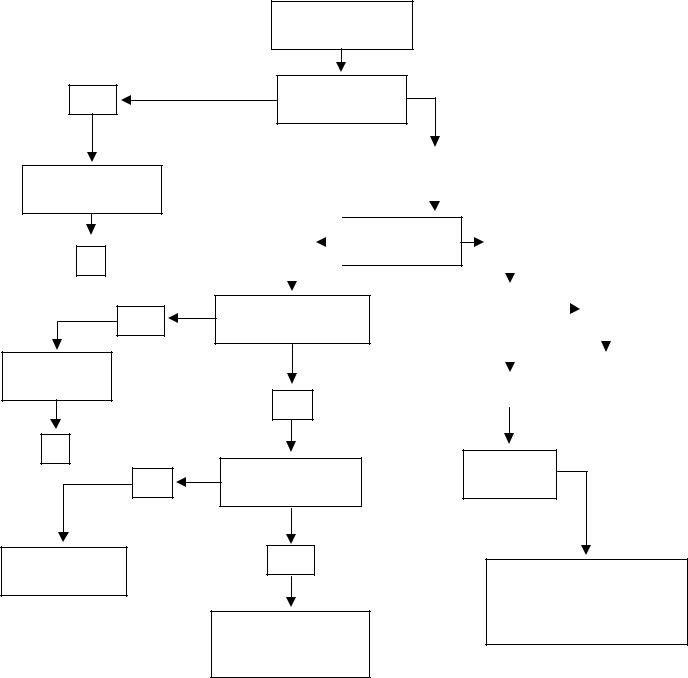
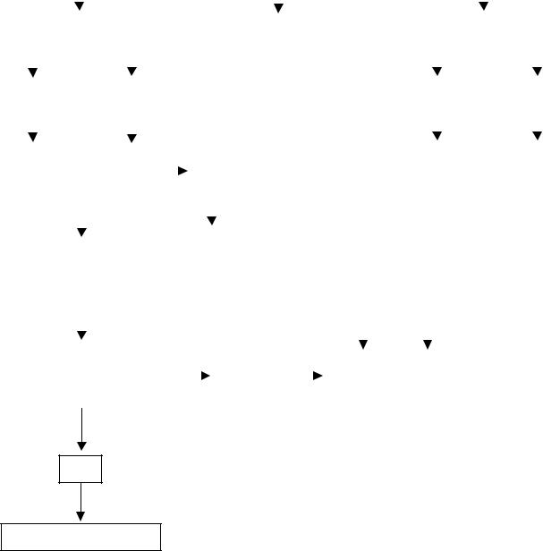
TROUBLESHOOTING (cont.)
Freezes, but not thick enough
Adjust thickness |
|
|
Brix ratio |
|
Too much |
|
Ambient |
||
screen higher |
|
|
too high |
|
alcohol in |
|
temperature |
||
|
|
|
|
||||||
|
|
|
|
|
|
product |
|
too hot |
|
|
|
|
|
|
|||||
|
|
|
|
|
|
|
|
|
|
|
|
|
|
|
|
|
|
|
|
Check for slightly |
|
|
|
Recommended |
bent auger shaft |
|
Adjust |
|
for indoor |
pins and/or weak |
|
product |
|
use only |
torsion springs. |
|
|
|
|
|
|
|
|
|
Check for dirty |
|
|
|
|
or worn seals and |
|
|
|
|
bushings. |
|
|
|
|
|
|
|
|
|
|
|
|
|
|
|
|
No hood lamps |
|
|
|
|
|
|
|
|
|
|
|
|
|
|||||||
|
|
|
|
|
|
|
|
|
|
|
|
|
|
|
|
|
|
|
|
|
|
|
|
|
|
|
|
|
|
|
|
|
|
|
|
|
|
|
|
|
|
|
|
|
|
|
|
|
|
|
|
|
|
|
|
|
|
|
|
|
|
|
|
|
|
|
|
|
|
|
|
|
|
|
|
|
|
|
|
|
|
|
|
|
|
|
|
|
|
|
Is dispenser in |
|
|
|
|
|
|
|
|
|
|
|
|
|
|
||||||
|
No |
|
|
|
|
|
|
|
|
Yes |
|
|
|
|
|
|
|
|
|||||||||
|
|
|
|
|
“DAY” mode? |
|
|
|
|
|
|
|
|
|
|
|
|
||||||||||
|
|
|
|
|
|
|
|
|
|
|
|
|
|
|
|
|
|
|
|
|
|||||||
|
|
|
|
|
|
|
|
|
|
|
|
|
|
|
|
|
|
|
|
|
|
|
|
|
|
|
|
|
|
|
|
|
|
|
|
|
|
|
|
|
|
|
|
|
|
|
|
|
|
|
|
|
|
|
|
|
|
|
|
|
|
|
|
|
|
|
|
|
|
|
|
|
|
|
|
||||||||
Set into |
|
|
|
|
|
|
|
|
|
Is circuit breaker |
|
|
|
|
|
|
|||||||||||
|
|
No |
|
|
|
|
|
|
|
Yes |
|
||||||||||||||||
“DAY” mode |
|
|
|
|
|
|
|
tripped? |
|
|
|
|
|
||||||||||||||
|
|
|
|
|
|
|
|
|
|
|
|
|
|||||||||||||||
|
|
|
|
|
|
|
|
|
|
|
|
|
|
|
|
|
|
|
|
|
|
|
|||||
|
|
|
|
|
|
|
|
|
|
|
|
|
|
|
|
|
|
|
|
|
|
||||||
|
|
|
|
|
|
|
Check lamp circuit |
|
|
|
|
|
|
Verify all 4 bulbs are 912 |
|||||||||||||
|
|
|
|
|
|
|
|
|
|
|
|
|
|
series & reset breaker |
|||||||||||||
|
|
|
|
|
|
|
|
|
|
|
|
|
|
|
|
|
|
|
|
|
|
||||||
|
|
|
|
|
|
|
|
|
|
|
|
|
|
|
|
|
|
|
|
|
|
|
|
|
|
|
|
17 |
41084 102709 |
|
TROUBLESHOOTING (cont.)
Noise
Auger jumping |
|
Check fan |
|
|
Using auger |
|
||
|
|
|
|
|
assembly from |
|
||
|
|
|
|
|
|
|
||
|
|
|
|
|
|
CDS 2 or 3? |
|
|
|
|
|
|
|
|
|
||
|
|
|
|
|
|
|
|
|
|
|
|
|
|
|
|
|
|
Lower brix ratio |
|
|
|
|
|
|
|
|
|
|
|
|
|
|
|
|
|
|
|
|
|
|
|
|
|
|
|
|
|
|
|
|
|
||
|
|
|
|
|
|
Replace with ULTRA |
||
|
|
|
|
|
|
|||
Drum alignment |
|
|
|
|
p/n 32106.1000 |
|||
|
|
|
|
|
|
|
||
|
|
|
|
|
|
|
|
|
|
|
|
|
|
|
|
|
|
Check auger shaft bushings
|
|
|
|
|
|
|
Auger won’t turn |
|
|
|
|
|
|
||
|
|
|
|
|
|
|
|
|
|
|
|
|
|
|
|
|
|
|
|
|
|
|
|
|
|
|
|
|
|
|
|
|
|
|
|
|
|
|
|
|
|
|
|
|
|
|
|
|
|
|
|
|
|
|
Do they turn during |
|
|
|
|
|
|
||
|
Yes |
|
|
|
“AUGER MOTOR TEST” |
|
|
|
No |
|
|||||
|
|
|
|
|
|
|
|
||||||||
|
|
|
|
|
|
|
mode? |
|
|
|
|
|
|
||
|
|
|
|
|
|
|
|
|
|
|
|
|
|||
|
|
|
|
|
|
|
|
|
|
|
|
|
|
|
|
|
|
|
|
|
|
|
|
|
|
|
|
|
|||
|
|
|
|
|
|
|
|
|
|
|
|
|
|
|
|
|
|
|
|
|
|
|
|
|
|
|
|
|
|
|
|
|
|
|
|
|
|
|
One direction, |
|
|
|
Auger motor/capacitor |
||||
|
|
|
|
|
|
|
but not the other |
|
|
|
checks |
||||
|
|
|
|
|
|
|
|
|
|
|
|
|
|
|
|
|
|
|
|
|
|
|
|
|
|
|
|||||
Check membrane |
|
|
|
|
|
|
|
|
|
|
|
|
|||
|
switch |
|
|
|
|
|
|
|
|
|
|
|
|||
|
|
|
|
|
|
|
|
|
|
|
|
|
|
|
|
|
|
|
|
|
|
|
|
|
|
|
|
|
|
|
|
|
|
|
|
|
|
|
Replace control |
|
|
|
|
|
|
|
|
|
|
|
|
|
|
|
board |
|
|
|
|
|
|
|
|
|
|
|
|
|
|
|
|
|
|
|
|
|
|
|
|
18 |
41084 102709 |
|
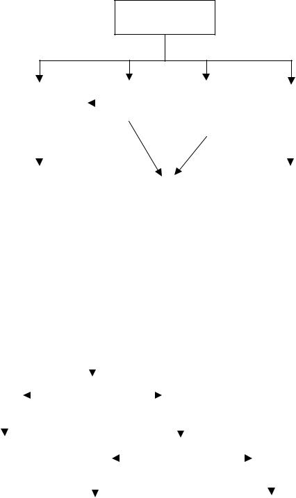
TROUBLESHOOTING (cont.) |
|
|
|
|
|
|
|
|
|
|
|
|
|
|
|
|
|
|
|
|
|
|
|
||||||||||||||
|
|
|
|
|
|
|
|
|
|
|
|
|
|
|
|
|
|
|
|
|
|
|
|
|
|
|
|
|
|
|
|
|
|
|
|
|
|
|
|
|
|
|
|
|
|
|
|
|
|
|
|
|
|
|
|
|
|
Torque Sensor Error |
|
|
|
|
|
|
|
|
|
|
|
|
|
||||
|
|
|
|
|
|
|
|
|
|
|
|
|
|
|
|
|
|
|
|
|
|
|
|
|
|
|
|
|
|
|
|||||||
|
|
|
|
|
|
|
|
|
|
|
|
|
|
|
|
|
|
|
|
|
|
|
|
|
|
|
|
|
|
|
|
|
|
|
|
|
|
|
|
|
|
|
|
|
|
|
|
|
|
|
|
|
|
|
|
|
|
|
|
|
|
|
|
|
|
|
|
|
|
|
|
|
|
|
|
|
|
|
|
|
|
|
|
|
|
|
|
|
|
|
|
|
|
|
|
|
|
|
|
|
|
|
|
|
|
|
|
|
|
|
|||
|
|
TORQUE SENSOR ERROR |
|
|
|
|
|
TORQUE SENSOR |
|
|
|
|
|
TORQUE SENSOR OPEN |
|||||||||||||||||||||||
|
|
|
|
|
|
|
|
|
|
|
|
|
|
|
|
|
|
|
|
|
SHORTED |
|
|
|
|
|
|
|
|
|
|
|
|
|
|
||
|
|
|
|
|
|
|
|
|
|
|
|
|
|
|
|
|
|
|
|
|
|
|
|
|
|
|
|
|
|
|
|
|
|||||
|
|
|
|
|
|
|
|
|
|
|
|
|
|
|
|
|
|
|
|
|
|
|
|
|
|
|
|
|
|
|
|
|
|
|
|
|
|
|
|
|
|
|
|
|
|
|
|
|
|
|
|
|
|
|
|
|
|
|
|
|
|
|
|
|
|
|
|
|
|
|
|
|
|
|
|
|
|
|
|
|
|
|
|
|
|
|
|
|
|
|
|
|
|
|
|
|
|
|
|
|
|
|
|
|
|
|
|
|
|
||||
|
|
Left side |
|
|
|
|
|
|
Right side |
|
|
|
|
|
|
|
|
|
|
|
|
|
|
Left side |
|
|
|
Right side |
|||||||||
|
|
|
|
|
|
|
|
|
|
|
|
|
|
|
|
|
|
|
|
|
|
|
|
|
|
|
|
|
|
|
|
||||||
|
|
|
|
|
|
|
|
|
|
|
|
|
|
|
|
|
|
|
|
|
|
|
|
|
|
|
|
|
|
|
|
|
|
|
|
|
|
|
|
|
|
|
|
|
|
|
|
|
|
|
|
|
|
|
|
|
|
|
|
|
|
|
|
|
|
|
|
|
|
|
|
|
|
|
|
|
|
|
|
Are augers |
|
|
|
|
|
|
|
|
|
|
|
|
|
|
|
|
|
Sensor unplugged or |
|
||||||||||||||
|
|
|
|
|
|
|
|
|
|
No |
|
|
|
|
|
|
|
|
|
||||||||||||||||||
|
|
|
|
|
turning? |
|
|
|
|
|
|
|
|
|
|
|
|
|
|
break in wiring |
|
||||||||||||||||
|
|
|
|
|
|
|
|
|
|
|
|
|
|
|
|
|
|
|
|
|
|
||||||||||||||||
|
|
|
|
|
|
|
|
|
|
|
|
|
|
|
|
|
|
|
|
|
|
|
|
||||||||||||||
|
|
|
|
|
|
|
|
|
|
|
|
|
|
|
|
|
|
|
|
|
|
|
|
|
|
|
|
|
|
|
|
|
|
|
|
|
|
|
|
|
|
|
|
|
|
|
|
|
|
|
|
|
|
|
|
|
|
|
|
|
|
|
|
|
|
|
|
|
|
||||||
|
|
|
|
|
|
|
|
|
|
|
|
|
|
|
|
|
|
|
|
|
|
|
|
|
|
|
|
|
|
|
|||||||
|
|
|
|
|
|
|
|
|
|
|
|
|
|
|
|
Go to motor |
|
|
|
|
|
|
|
|
|
|
|
|
|
|
|
|
|||||
|
|
|
|
|
|
|
Yes |
|
|
|
|
|
|
|
|
|
|
|
|
|
|
|
|
|
|
|
|
|
|||||||||
|
|
|
|
|
|
|
|
|
troubleshooting |
|
|
|
|
|
|
|
|
|
|
|
|
|
|
|
|
||||||||||||
|
|
|
|
|
|
|
|
|
|
|
|
|
|
|
|
|
|
|
|
|
|
|
|
|
|
|
|
|
|||||||||
|
|
|
|
|
|
|
|
|
|
|
|
|
|
|
|
|
|
|
|
|
|
|
|
|
|
|
|
|
|
|
|||||||
|
|
|
|
|
|
|
|
|
|
|
|
|
|
|
|
|
|
|
|
|
|
|
|
|
|
|
|
|
|
|
|
|
|
|
|
|
|
|
|
|
|
|
|
|
|
|
|
|
|
|
|
|
|
|
|
|
|
|
|
|
|
|
|
|
|
|
|
|
|
|
|
|
|
|
|
|
|
|
|
|
|
|
|
|
|
|
|
|
|
|
|
|
|
|
|
|
|
|
|
|
|
|
|
|
|
|
|
|
|
|
|
|
|
Are augers shaft pins |
|
|
|
|
|
|
|
|
|
|
|
Check sensor |
|
|
|
No |
|
|
||
damaged or missing? |
|
|
|
|
||
|
|
|
|
circuit |
||
|
|
|
|
|
|
|
|
|
|
|
|
|
|
Yes
Replace as necessary
19 |
41084 102709 |
|

TROUBLESHOOTING (cont.)
|
|
|
|
|
|
|
|
|
|
Temperature Sensor Error |
|
|
|
|
|
|
|
|
|
|
|
||||||
|
|
|
|
|
|
|
|
|
|
|
|
|
|
|
|
|
|
|
|
|
|||||||
|
|
|
|
|
|
|
|
|
|
|
|
|
|
|
|
|
|
|
|
|
|
|
|
|
|
|
|
|
|
|
|
|
|
|
|
|
|
|
|
|
|
|
|
|
|
|
|
|
|
|
|
|
|||
|
TEMPERATURE SENSOR SHORTED |
|
|
|
|
|
|
|
TEMPERATURE SENSOR OPEN |
||||||||||||||||||
|
|
|
|
|
|
|
|
|
|
|
|
|
|
|
|
|
|
|
|
|
|
|
|
|
|
||
|
|
|
|
|
|
|
|
|
|
|
|
|
|
|
|
|
|
|
|
|
|
|
|
|
|
|
|
|
|
|
|
|
|
|
|
|
|
|
|
|
|
|
|
|
|
|
|
|
|
||||||
|
|
Left side |
|
|
Right side |
|
|
|
|
|
|
|
|
|
|
Left side |
|
|
Right side |
|
|||||||
|
|
|
|
|
|
|
|
|
|
|
|
|
|
|
|
|
|
|
|
|
|||||||
|
|
|
|
|
|
|
|
|
|
|
|
|
|
|
|
|
|
|
|
|
|
|
|
|
|
|
|
|
|
|
|
|
|
|
|
|
|
|
|
|
|
||||||||||||||
|
Check wiring harness between |
|
|
|
|
|
|
|
|
|
Product not covering |
|
|||||||||||||||
|
thermistor and control board |
|
|
|
|
|
|
|
|
|
back end of drum. |
|
|||||||||||||||
|
|
|
|
|
|
|
|
|
|
|
|
|
|
|
|
|
|
|
Drum temperature |
|
|||||||
|
|
|
|
|
|
|
|
|
|
|
|
|
|
|
|
|
|
||||||||||
|
|
|
|
|
|
|
|
|
|
|
|
|
|
|
|
|
|
|
|
|
|||||||
|
|
|
|
|
|
|
|
|
|
|
|
|
|
|
|
|
|
|
|
falls below 9° F. |
|
||||||
|
|
|
|
|
|
|
|
|
|
|
|
|
|
|
|
|
|
|
Replenish product |
|
|||||||
|
|
|
|
|
|
|
|
|
|
|
|
|
|
|
|
|
|
|
|
|
|
||||||
|
|
|
|
|
|
|
|
|
|
|
|
|
|
|
|
|
|
|
|
|
|||||||
|
|
|
|
|
|
|
|
|
|
|
|
|
|
|
|
|
|
|
|
||||||||
|
|
|
|
|
|
|
|
|
|
|
|
|
|
|
|
|
|
|
Thermistor unplugged |
|
|
||||||
|
|
|
|
|
|
|
|
|
|
|
|
|
|
|
|
|
|
|
|
or break in wiring |
|
|
|||||
|
|
|
|
|
|
|
|
|
|
|
|
|
|
|
|
|
|
|
|
|
|
|
|||||
|
|
|
|
|
|
|
|
|
|
|
|
|
|
|
|
|
|
|
|
|
|
|
|
|
|
|
|
|
|
|
|
|
|
|
|
|
|
|
|
|
|
|
|
|
|
|
|
||||||||
|
|
|
|
|
|
|
|
|
|
|
|
Check thermistor |
|
|
|
|
|
|
|
|
|
|
|
|
|
||
|
|
|
|
|
|
|
|
|
|
|
|
circuit |
|
|
|
|
|
|
|
||||||||
|
|
|
|
|
|
|
|
|
|
|
|
|
|
|
|
|
|
|
|
|
|
|
|
|
|
|
|
20 |
41084 102709 |
|
TROUBLESHOOTING (cont.)
Clean Filter Messages
|
“MONTHLY FILTER |
|
|
“FILTER NEEDS |
|
|
|
“FILTER NEEDS |
|
||||
|
CLEAN REQUIRED” |
|
|
CLEANING” |
|
|
|
!!!CLEANING!!!” |
|
||||
|
|
|
|
|
|
|
|
|
|
|
|
|
|
|
|
|
|
|
|
|
|
|
|
|
|
|
|
|
|
|
|
|
|
|
|
|
|
|
Freezing is Disabled |
|
|
|
|
|
|
|
|
|
|
|
|
|
|
|
|
|
|
|
|
|
|
|
|
|
|
|
|||
|
Monthly reminder |
|
|
|
Hot gas thermistor |
|
|
|
Hot gas thermistor |
|
|||
|
|
|
|
|
|
sensing over 220° F |
|
|
|
sensing over 250° F |
|
||
|
|
|
|
|
|
|
|
|
|
||||
|
|
|
|
|
|
|
|
|
|
|
|
|
|
|
|
|
|
|
|
|
|
|
|
|
|
|
|
|
|
|
|
|
|
|
|
|
|
|
|
|
|
|
|
Dirty filter; air flow blockage; |
Clean filter |
|
|
|
wrong refrigerant or over charged |
|
|
|
|
|
|
|
|
|
|
Hold ULTRA button for 3 seconds to reset. *
* Early units have to reset to factory defaults in order to reset
21 |
41084 102709 |
|
 Loading...