


 H10X/H5X H5E/DV PC H5 ELEMENT
With Digital Control Board
SERVICE MANUAL
BUNN-O-MATIC CORPORATION
POST OFFICE BOX 3227
SPRINGFIELD, ILLINOIS 62708-3227
PHONE: (217) 529-6601 FAX: (217) 529-6644
To ensure you have the latest revision of the manual or to obtain the illustrated parts catalog, please visit the Bunn-O-Matic website, at www.bunn.com. This is absolutely FREE, and the quickest way to obtain the latest catalog and manual updates. Contact Bunn-O-Matic Corporation at 1-800-286-6070 to obtain a paper copy of the required Illustrated Parts Catalog mailed via U.S. Postal Service.
42311.0000E 09/13 © 2011 BUNN-O-MATIC CORPORATION
BUNN-O-MATIC COMMERCIAL PRODUCT WARRANTY
Bunn-O-Matic Corp. (“BUNN”) warrants equipment manufactured by it as follows:
1)Airpots, thermal carafes, decanters, GPR servers, iced tea/coffee dispensers, MCP/MCA pod brewers thermal servers and Thermofresh servers (mechanical and digital)- 1 year parts and 1 year labor.
2)All other equipment - 2 years parts and 1 year labor plus added warranties as specified below:
a)Electronic circuit and/or control boards - parts and labor for 3 years.
b)Compressors on refrigeration equipment - 5 years parts and 1 year labor.
c)Grinding burrs on coffee grinding equipment to grind coffee to meet original factory screen sieve analysis - parts and labor for 4 years or 40,000 pounds of coffee, whichever comes first.
These warranty periods run from the date of installation BUNN warrants that the equipment manufactured by it will be commercially free of defects in material and workmanship existing at the time of manufacture and appearing within the applicable warranty period. This warranty does not apply to any equipment, component or part that was not manufactured by BUNN or that, in BUNN’s judgment, has been affected by misuse, neglect, alteration, improper installation or operation, improper maintenance or repair, non periodic cleaning and descaling, equipment failures related to poor water quality, damage or casualty. In addition, the warranty does not apply to replacement of items subject to normal use including but not limited to user replaceable parts such as seals and gaskets. This warranty is conditioned on the Buyer 1) giving BUNN prompt notice of any claim to be made under this warranty by telephone at (217) 529-6601 or by writing to Post Office Box 3227, Springfield, Illinois 62708-3227; 2) if requested by BUNN, shipping the defective equipment prepaid to an authorized BUNN service location; and 3) receiving prior authorization from BUNN that the defective equipment is under warranty.
THE FOREGOING WARRANTY IS EXCLUSIVE AND IS IN LIEU OF ANY OTHER WARRANTY, WRITTEN OR ORAL, EXPRESS OR IMPLIED, INCLUDING, BUT NOT LIMITED TO, ANY IMPLIED WARRANTY OF EITHER MERCHANTABILITY OR FITNESS FOR A PARTICULAR PURPOSE. The agents, dealers or employees of BUNN are not authorized to make modifications to this warranty or to make additional warranties that are binding on BUNN. Accordingly, statements by such individuals, whether oral or written, do not constitute warranties and should not be relied upon.
If BUNN determines in its sole discretion that the equipment does not conform to the warranty, BUNN, at its exclusive option while the equipment is under warranty, shall either 1) provide at no charge replacement parts and/or labor (during the applicable parts and labor warranty periods specified above) to repair the defective components, provided that this repair is done by a BUNN Authorized Service Representative; or 2) shall replace the equipment or refund the purchase price for the equipment.
THE BUYER’S REMEDY AGAINST BUNN FOR THE BREACH OF ANY OBLIGATION ARISING OUT OF THE SALE OF THIS EQUIPMENT, WHETHER DERIVED FROM WARRANTY OR OTHERWISE, SHALL BE LIMITED, AT BUNN’S SOLE OPTION AS SPECIFIED HEREIN, TO REPAIR, REPLACEMENT OR REFUND.
In no event shall BUNN be liable for any other damage or loss, including, but not limited to, lost profits, lost sales, loss of use of equipment, claims of Buyer’s customers, cost of capital, cost of down time, cost of substitute equipment, facilities or services, or any other special, incidental or consequential damages.
392, A Partner You Can Count On, Air Infusion, AutoPOD, AXIOM, BrewLOGIC, BrewMETER, Brew Better Not Bitter, BrewWISE, BrewWIZARD, BUNN Espress, BUNN Family Gourmet, BUNN Gourmet, BUNN Pour-O-Matic, BUNN, BUNN with the stylized red line, BUNNlink, Bunn-OMatic, Bunn-O-Matic, BUNNserve, BUNNSERVE with the stylized wrench design, Cool Froth, DBC, Dr. Brew stylized Dr. design, Dual, Easy Pour, EasyClear, EasyGard, FlavorGard, Gourmet Ice, Gourmet Juice, High Intensity, iMIX, Infusion Series, Intellisteam, My Café, Phase Brew, PowerLogic, Quality Beverage Equipment Worldwide, Respect Earth, Respect Earth with the stylized leaf and coffee cherry design, Safety-Fresh, savemycoffee.com, Scale-Pro, Silver Series, Single, Smart Funnel, Smart Hopper, SmartWAVE, Soft Heat, SplashGard, The Mark of Quality in Beverage Equipment Worldwide, ThermoFresh, Titan, trifecta, Velocity Brew, Air Brew, Beverage Bar Creator, Beverage Profit Calculator, Brew better, not bitter., BUNNSource, Coffee At Its Best, Cyclonic Heating System, Daypart, Digital Brewer Control, Element, Milk Texturing Fusion, Nothing Brews Like a BUNN, Pouring Profits, Signature Series, Sure Tamp, Tea At Its Best, The Horizontal Red Line, Ultra are either trademarks or registered trademarks of Bunn-O-Matic Corporation. The commercial trifecta® brewer housing configuration is a trademark of Bunn-O-Matic Corporation.
2 |
42311 070913 |
|
WARNING - Inspection, testing, and repair of electrical equipment should be performed only by qualified service personnel. Disconnect the dispenser fromthe power source when servicing, except when electrical tests are required and the test procedure specifically states to connect the dispenser to the power source.
|
CONTENTS |
TroubleShooting............................................................................................ |
4 |
Component Access........................................................................................ |
7 |
Electronic Controls................................................................................... |
8-11 |
Limit Thermostat......................................................................................... |
12 |
Safety Overflow Switch................................................................................ |
13 |
Solenoid Valve (Late Models) |
14 |
Solenoid Valve (Early Models) |
15 |
Tank Heater.................................................................................................. |
16 |
Steam Sensor.............................................................................................. |
17 |
Dispense Valve (PC).................................................................................... |
18 |
Schematic Wiring Diagrams |
19 |
3 |
42311 071310 |
|
TROUBLESHOOTING
A troubleshooting guide is provided to suggest probable causes and remedies for the most likely problems encountered. If the problem remains after exhausting the troubleshooting steps, contact the Bunn-O-Matic Technical Service Department.
•Inspection, testing, and repair of electrical equipment should be performed only by qualified service personnel.
•All electronic components have 120 – 240 volt ac and low voltage dc potential on their terminals. Shorting of terminals or the application of external voltages may result in board failure.
•Intermittent operation of electronic circuit boards is unlikely. Board failure will normally be permanent. If an intermittent condition is encountered, the cause will likely be a switch contact or a loose connection at a terminal or crimp.
•Solenoid removal requires interrupting the water supply to the valve. Damage may result if solenoids are energized for more than ten minutes without a supply of water.
•The use of two wrenches is recommended whenever plumbing fittings are tightened or loosened. This will help to avoid twists and kinks in the tubing.
•Make certain that all plumbing connections are sealed and electrical connections tight and isolated.
•This dispenser is heated at all times. Keep away from combustibles.
WARNING
•Exercise extreme caution when servicing electrical equipment.
•Disconnect dispenser from the power source when servicing, except when electrical tests are specified.
•Follow recommended service procedures
•Replace all protective shields or safety notices
|
|
|
When a fault occurs (failure to the unit) the POWER lamp will |
|
FAULT CODES |
|
flash to identify the problem (early models) |
||
|
Flashes |
Description of Failure |
||
|
|
|
||
Er1 |
Temperature Sensor (short) |
|
1 |
Temperature Sensor (short) |
Er2 |
Temperature Sensor (open) |
|
2 |
Temperature Sensor (open) |
Er3 |
Refill Fault (continuous refill for 15 minutes) |
3 |
Refill Fault (continuous refill for 15 minutes) |
|
Er4 |
Heater Fault (heater relay on for 120 minutes) |
4 |
Heater Fault (heater relay on for 120 minutes) |
|
Er5 |
Boil Thermistor (short) H5X/H10X only) |
5 |
Boil Thermistor (short) H5X/H10X only |
|
Er6 |
Boil Thermistor (open) H5X/H10X only) |
6 |
Boil Thermistor (open) H5X/H10X only |
|
Problem |
Probable Cause |
|
Remedy |
|
Equipment will not operate. |
1. No power or incorrect voltage |
(A) Check the terminal block for the cor- |
||
rect voltage. It should be:
a.) 100 to 120 volts ac across the black and white terminals for 100 to 120 volt models or,
b.) 200 to 240 volts ac across the red and black terminals for 200 to 240 volt models or,
c.) 230 volts ac across the red and black terminals for 230 volt models.
(B) Check circuit breakers or fuses.
4 |
42311 071310 |
|
TROUBLESHOOTING (cont.) |
|
|
|
Problem |
Probable Cause |
Remedy |
|
Equipment will not operate |
2. |
Safety overflow switch |
Refer to Service – safety overflow switch |
(cont.) |
|
|
for testing procedures. |
Automatic refill will not oper- |
1. |
No water |
Check plumbing and shut-off valves. |
ate after drawing hot water. |
2. |
Water strainer/flow control |
(A) Direction of flow arrow must be point- |
|
|||
|
|
|
ing towards dispenser. |
|
|
|
(B) Remove the strainer/flow control and |
|
|
|
check for obstructions. Clear or replace. |
|
3. |
Liquid level system |
Refer to Service – electronic controls for |
|
|
|
testing procedures. |
|
4. |
Solenoid valve |
Refer to Service – solenoid valve for test- |
|
|
|
ing procedures. |
Water flows into the tank con- |
1. |
Solenoid valve |
Refer to Service – solenoid valve for test- |
tinuously (Dispenser discon- |
|
|
ing procedures. |
nected from power source). |
|
|
|
Water flows into the tank con- |
1. |
Liquid level system |
Refer to Service – electronic controls for |
tinuously (Dispenser connect- |
|
|
testing procedures. |
ed to power source). |
|
|
|
Water is cold. |
1. |
Safety overflow switch |
Refer to Service – safety overflow switch |
|
|
|
for testing procedures. |
|
2. |
Limit thermostat |
Refer to Service – limit thermostat for |
|
|
|
testing procedures. |
CAUTION – Do not eliminate or bypass limit thermostat. Use only B.O.M. replacement part #23717.0003.
3. |
Tank heater |
Refer to Service – tank heater for testing |
|
|
procedures. |
4. |
Temperature control |
Refer to Service – electronic controls for |
|
|
testing procedures. |
5 |
42311 071310 |
|
TROUBLESHOOTING (cont.) |
|
|
|
Problem |
Probable Cause |
Remedy |
|
Water boils continuously. |
1. |
Temperature control |
Refer to Service – electronic controls for |
|
|
|
testing procedures. |
|
2. |
Lime build-up |
Inspect the tank assembliy for excess lime |
|
|
|
deposits. Delime as required. |
CAUTION – Tanks and tank components should be delimed reglarly depending on local water conditions. Excessive mineral build-up on stainless steel surfaces can initiate corrosive reactions resulting in serious leaks.
Dispenser is making unusual 1. |
Plumbing lines |
noises. |
|
3. |
Water supply |
Ready indicator will not light. |
1. |
Temperature control |
|
2. |
Ready Indicator LED |
Plumbing lines should not be resting on the counter top.
(A)The dispenser must be connected to a cold water line.
(B)Water pressure to the dispenser must not be higher than 90 psi (620 kPa). Install a regulator if necessary to lower the working pressure to approximately 50 psi (345 kPa).
Refer to Service – electronic controls for testing procedures.
Replace the indicator LED.
6 |
42311 071310 |
|
SERVICE
WARNING – Disconnect the dispenser from the power source before the removal of any panel or the replacement of any component. WARNING - Inspection, testing, and repair of electrical equipment should be performed only by qualified service personnel. Disconnect the dispenser fromthe power source when servicing, except when electrical tests are required and the test procedure specifically states to connect the dispenser to the power source.
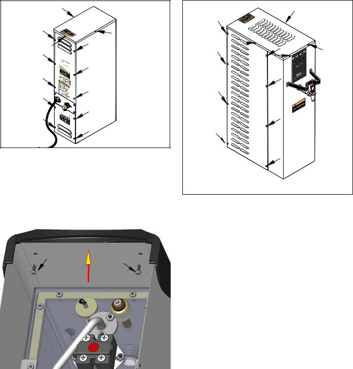
Component Access - H5E/DV-PC/X |
Component Access - H10X |
||
|
|
|
|
P1770.30
The check valve, electronic control assembly, safety overflow switch, solenoid valve, overflow tube temperature sensor and terminal block are located at the rear of the dispenser. Access is gained by removing the upper and lower rear panels. The upper is attached with six 8-32 slotted-head screws. The lower is attached with four 8-32 slotted-head screws. The middle panel must not be removed from the dispenser.
! |
WARNING |
|
Hot |
Water |
|
|
Care! |
|
VeryWith |
|
|
Use |
|
|
P878.30
@ The check valve, electronic control assembly, overflow protection switch, solenoid valve, overflow tube temperature sensor, triac assembly (EARLY MODELS ONLY) and terminal block are located on the side of the dispenser. Access is gained by removing the side panel. The panel is attached with eight 8-32 slottedhead screws.
Faceplate Removal - H5 ELEMENT: After removing top cover, remove the two upper screws securing the faceplate. Carefully lift faceplate straight up until the three lower screws clear the key holes.
7 |
42311 022311 |
|

SERVICE |
Liquid Level Control Flow Charts |
|
|
||
Electronic Controls |
|
|
|||
|
|
|
|
|
|
|
H5E, H5X LIQUID LEVEL CONTROL |
|
|
||
|
PROBLEM: Does Not Refill |
|
|
|
|
|
Overflow Cup Full |
Yes |
Remove Power |
|
|
|
|
|
|
||
|
? |
|
|
|
|
|
|
|
Drain cup |
|
|
|
No |
|
Retry |
|
|
|
|
|
|
|
|
|
Disconnect Level Probe |
|
|
|
|
|
Voltage present at |
Yes |
Does Water Flow |
Yes |
Replace Probe |
|
Solenoid Valve |
|
|
||
|
|
? |
|
|
|
|
? |
|
|
|
|
|
|
|
|
|
|
H 5 |
No |
|
No |
|
|
Unplug Ready Lamp |
|
Replace Solenoid Valve |
|
|
|
|
|
|
|
||
P4093.35 |
|
|
|
|
|
FIG. 8a ELECTRONIC CONTROL |
Voltage present at |
Yes |
Replace Ready Lamp |
|
|
|
Solenoid Valve |
|
|
|
|
|
? |
|
|
|
|
|
No |
|
|
|
|
|
Replace Control Board |
|
|
|
|
Triac Assy |
|
|
|
|
|
|
H5E, H5X LIQUID LEVEL CONTROL |
|
|
||
|
PROBLEM: Overflows |
|
|
|
|
|
Drain cup |
|
|
|
|
Electronic |
Unplug Ready Lamp |
|
|
|
|
Retry |
|
|
|
|
|
Control Board |
|
|
|
|
|
|
|
|
|
|
|
|
Overflow |
No |
Replace Ready Lamp |
|
|
|
|
|
|
||
|
? |
|
|
|
|
|
|
|
|
|
|
H 10 |
Yes |
|
|
|
|
|
|
|
|
|
|
|
Drain cup |
|
|
|
|
|
Disconnect Probe |
|
|
|
|
P1991-1.30 |
Wire From Probe |
|
|
|
|
Short Probe Wire |
|
|
|
|
|
FIG. 8b ELECTRONIC CONTROL |
Retry |
|
|
|
|
|
To Chassis |
|
|
|
|
BOARD AND TRIAC |
|
|
|
|
|
Location:
The electronic control board is located inside the rear of the dispenser. Access will also be needed to the temperature sensor, overflow tube temperature sensor, and liquid level probe located on the tank lid.
General:
This system controls the liquid level and water temperature of the dispenser. These two functions act independently of each other and should be tested separately.
Overflow |
No |
Replace Probe |
||
? |
|
|
||
|
|
|
||
Yes |
|
|
|
|
|
|
|
|
|
Drain cup |
|
|
|
|
|
|
|
|
|
Disconnect Wire From |
|
|
|
|
Solenoid Valve |
|
|
|
|
Retry |
|
|
|
|
|
Yes |
|
||
Overflow |
|
|||
Replace Solenoid Valve |
||||
? |
|
|
||
|
|
|
||
 No
No
Replace Control Board
8 |
42311 071310 |
|
 Loading...