


 Loading...
S-7200C |
SERVICE MANUAL |
|
Please read this manual before making any adjustments.
SINGLE NEEDLE DIRECT DRIVE STRAIGHT LOCK STITCHER WITH THREAD TRIMMER
This service manual is intended for S-7200C; be sure to read the S-7200C instruction manual before this manual.
Carefully read the “SAFETY INSTRUCTIONS” and the whole of this manual to understand this product before you start maintenance.
As a result of research and improvements regarding this product, some details of this manual may not be the same as those for the product you purchased.
If you have any questions regarding this product, please contact a Brother dealer.
S-7200C

SAFETY INSTRUCTIONS
[1] Safety indications and their meanings
This service manual and the indications and symbols that are used on the machine itself are provided in order to ensure safe operation of this machine and to prevent accidents and injury to yourself or other people.
The meanings of these indications and symbols are given below.
Indications
DANGER |
The instructions which follow this term indicate situations where failure to follow the |
instructions will result in death or serious injury. |
|
|
|
CAUTION |
The instructions which follow this term indicate situations where failure to follow the |
instructions could cause injury when using the machine or physical damage to |
|
|
equipment and surroundings. |
Symbols |
|
 · · · · ·
 · · · · ·
 · · · · ·
This symbol (  ) indicates something that you should be careful of. The picture inside the triangle indicates the nature of the caution that must be taken.
(For example, the symbol at left means “beware of injury”.)
This symbol (  ) indicates something that you must not do.
This symbol (  ) indicates something that you must do. The picture inside the circle indicates the nature of the thing that must be done.
(For example, the symbol at left means “you must make the ground connection”.)
S-7200C |
i |
[2] Notes on safety
 DANGER
Wait at least 5 minutes after turning off the power switch and disconnecting the power cord from the wall outlet before opening the cover of the control box. Touching areas where high voltages are present can result in severe injury.
 CAUTION
Environmental requirements
Use the sewing machine in an area which is free from sources of strong electrical noise such as electrical line noise or static electric noise.
Sources of strong electrical noise may cause problems with correct operation.
Any fluctuations in the power supply voltage should be within ±10% of the rated voltage for the machine.
Voltage fluctuations which are greater than this may cause problems with correct operation.
The power supply capacity should be greater than the requirements for the sewing machine's power consumption.
Insufficient power supply capacity may cause problems with correct operation.
The ambient temperature should be within the range of 5°C to 35°C during use.
Temperatures which are lower or higher than this may cause problems with correct operation.
The relative humidity should be within the range of 45% to 85% during use, and no dew formation should occur in any devices.
Excessively dry or humid environments and dew formation may cause problems with correct operation.
In the event of an electrical storm, turn off the power and disconnect the power cord from the wall outlet. Lightning may cause problems with correct operation.
Installation
Machine installation should only be carried out by a qualified technician.
Contact your Brother dealer or a qualified electrician for any electrical work that may need to be done.
The sewing machine weighs more than 45 kg. The installation should be carried out by two or more people.
Do not connect the power cord until installation is complete. The machine may operate if the treadle is depressed by mistake, which could result in injury.
Turn off the power switch before inserting or removing the plug, otherwise damage to the control box could result.
Be sure to connect the ground. If the ground connection is not secure, you run a high risk of receiving a serious electric shock, and problems with correct operation may also occur.
When securing the cords, do not bend the cords excessively or fasten them too hard with staples, otherwise there is the danger that fire or electric shocks could occur.
If using a work table which has casters, the casters should be secured in such a way so that they cannot move.
Secure the table so that it will not move when tilting back the machine head. If the table moves, it may crush your feet or cause other injuries.
Use both hands to hold the machine head when tilting it back or returning it to its original position. If only one hand is used, the weight of the machine head may cause your hand to slip, and your hand may get caught.
Be sure to wear protective goggles and gloves when handling the lubricating oil and grease, so that they do not get into your eyes or onto your skin, otherwise inflammation can result.
Furthermore, do not drink the oil or eat the grease under any circumstances, as they can cause vomiting and diarrhea.
Keep the oil out of the reach of children.
ii |
S-7200C |
 CAUTION
Sewing
This sewing machine should only be used by operators who have received the necessary training in safe use beforehand.
The sewing machine should not be used for any applications other than sewing.
Be sure to wear protective goggles when using the machine.
If goggles are not worn, there is the danger that if a needle breaks, parts of the broken needle may enter your eyes and injury may result.
Turn off the power switch at the following times. The machine may operate if the treadle is depressed by mistake, which could result in injury.
When threading the needle
When replacing the bobbin and needle
When not using the machine and when leaving the machine unattended
If using a work table which has casters, the casters should be secured in such a way so that they cannot move.
Attach all safety devices before using the sewing machine. If the machine is used without these devices attached, injury may result.
Do not touch any of the moving parts or press any objects against the machine while sewing, as this may result in personal injury or damage to the machine.
Secure the table so that it will not move when tilting back the machine head. If the table moves, it may crush your feet or cause other injuries.
Use both hands to hold the machine head when tilting it back or returning it to its original position. If only one hand is used, the weight of the machine head may cause your hand to slip, and your hand may get caught.
If an error occurs in machine operation, or if abnormal noises or smells are noticed, immediately turn off the power switch. Then contact your nearest Brother dealer or a qualified technician.
If the machine develops a problem, contact your nearest Brother dealer or a qualified technician.
Cleaning
Turn off the power switch before carrying out cleaning. The machine may operate if the treadle is depressed by mistake, which could result in injury.
Secure the table so that it will not move when tilting back the machine head. If the table moves, it may crush your feet or cause other injuries.
Use both hands to hold the machine head when tilting it back or returning it to its original position. If only one hand is used, the weight of the machine head may cause your hand to slip, and your hand may get caught.
Be sure to wear protective goggles and gloves when handling the lubricating oil and grease, so that they do not get into your eyes or onto your skin, otherwise inflammation can result.
Furthermore, do not drink the oil or eat the grease under any circumstances, as they can cause vomiting and diarrhea.
Keep the oil out of the reach of children.
Use only the proper replacement parts as specified by Brother.
Maintenance and inspection
Disassembly, assembly, maintenance and inspection of the sewing machine should only be carried out by a qualified technician.
Ask your Brother dealer or a qualified electrician to carry out any maintenance and inspection of the electrical system.
Turn off the power switch and disconnect the power cord from the wall outlet at the following times, otherwise the machine may operate if the treadle is depressed by mistake, which could result in injury.
When carrying out inspection, adjustment and maintenance
When replacing consumable parts such as the rotary hook
If the power switch needs to be left on when carrying out some adjustment, be extremely careful to observe all safety precautions.
Turn off the power switch before inserting or removing the plug, otherwise damage to the control box could result.
Secure the table so that it will not move when tilting back the machine head. If the table moves, it may crush your feet or cause other injuries.
Use both hands to hold the machine head when tilting it back or returning it to its original position.
If only one hand is used, the weight of the machine head may cause your hand to slip, and your hand may get caught.
Use only the proper replacement parts as specified by Brother.
If any safety devices have been removed, be absolutely sure to re-install them to their original positions and check that they operate correctly before using the machine.
Any problems in machine operation which result from unauthorized modifications to the machine will not be covered by the warranty.
S-7200C |
iii |

[3] Warning labels
The following warning labels appear on the sewing machine.
Please follow the instructions on the labels at all times when using the machine. If the labels have been removed or are difficult to read, please contact your nearest Brother dealer.
1
2 
Touching areas where high voltages are present can |
4 |
|
Be careful not to get your hands |
result in severe injury. Turn off the power before |
|
caught when returning the |
|
opening the cover. |
|
|
machine head to its original |
|
|
|
position after it has been tilted. |
|
|
|
3
*Safety devices: (A) Finger guard
(B)Thread take-up cover
5 
6
7
Be careful to avoid injury from the moving thread take-up.
Be sure to connect the ground. If the ground connection is not secure, you run a high risk of receiving a serious electric shock, and problems with correct operation may also occur.
Direction of operation
Oil pan
Control box |
Transformer box |
|
|
(100 V/400 V system only) |
4123M |
|
|
iv |
S-7200C |
S-7200C

CONTENTS
1. MACHINE SPECIFICATIONS.............. |
1 |
2. NOTES ON HANDLING........................ |
2 |
3. COMPARISON OF FUNCTIONS |
|
(G50 AND G10 OPERATION PANELS)... |
3 |
4. FUNCTION SETTINGS |
|
(G50 OPERATION PANEL).................. |
4 |
4-1. List of advanced functions ................................... |
4 |
4-2. List of special functions when power is turned on.. |
5 |
4-3. Maximum sewing speed and start backtack |
|
sewing speed setting methods............................. |
6 |
4-4. Using the LOCK key ............................................ |
7 |
4-5. Memory switch setting method (Standard)........... |
8 |
4-6. Memory switch setting method (Advanced) ......... |
13 |
4-7. Data initialization function .................................... |
22 |
4-8. Error history checking method ............................. |
23 |
4-9. Input checking method......................................... |
24 |
4-10. Output checking method.................................... |
29 |
4-11. Protection settings ............................................. |
32 |
4-12. Software version checking method .................... |
35 |
4-13. Viewing maintenance information ...................... |
36 |
4-14. Adjusting the sewing machine reference |
|
position .............................................................. |
37 |
5. FUNCTION SETTINGS |
|
(G10 OPERATION PANEL)................. |
38 |
5-1. List of special functions when power is turned on.. |
38 |
5-2. Function setting method....................................... |
39 |
5-3. Data initialization function .................................... |
41 |
5-4. Error history checking method ............................. |
42 |
5-5. Input checking method......................................... |
43 |
5-6. Output checking method ...................................... |
48 |
5-7. Protection settings ............................................... |
51 |
5-8. Software version checking method ...................... |
54 |
5-9. Viewing maintenance information ........................ |
55 |
5-10. Adjusting the sewing machine reference position.. 56 |
|
6. SETTING THE DIP SWITCHES |
|
(G50 AND G10 OPERATION PANELS)... |
57 |
7. MECHANICAL DESCRIPTIONS ......... |
58 |
7-1. Upper shaft and needle bar mechanism .............. |
58 |
7-2. Lower shaft and rotary hook mechanism ............. |
59 |
7-3. Feed mechanism ................................................. |
60 |
7-4. Quick reverse mechanism |
|
(quick back mechanism) ...................................... |
61 |
7-5. Lubrication mechanism |
|
(thread take-up and rotary hook).......................... |
62 |
7-6. Thread trimming mechanism................................ |
63 |
7-6-1. Thread trimming mechanism operation |
|
sequence.................................................... |
63 |
7-6-2. Upper and lower thread trimming sequence ... |
65 |
7-7. Tension release mechanism................................ |
66 |
7-8. Thread wiper mechanism (option device) ............ |
67 |
8. DISASSEMBLY .................................... |
68 |
8-1. Knee lifter assembly ............................................ |
68 |
8-2. Cable tie .............................................................. |
69 |
8-3. Connector ............................................................ |
69 |
8-4. Operation panel and head detector unit .............. |
70 |
8-5. Covers and bobbin winder unit ............................ |
71 |
8-6. Tension release wire and thread trimmer solenoid.. 72 |
|
8-7. Wick holder and oil tube (-[]0[] specifications) ..... |
73 |
8-8. Oil tank, bed bottom cover and sub tank ............. |
74 |
8-9. Stand ................................................................... |
75 |
8-10. Safety switch and quick reverse solenoid.......... |
75 |
8-11. Needle, presser foot and R-actuator ................. |
76 |
8-12. Thread tension mechanism ............................... |
76 |
8-13. Needle plate, feed dog, etc................................ |
77 |
8-14. Bobbin case, rotary hook and thread trimmer |
|
mechanism ........................................................ |
78 |
8-15. Feed bar mechanism......................................... |
79 |
8-16. Feed rock shaft.................................................. |
79 |
8-17. Presser foot mechanism.................................... |
80 |
8-18. Knee lifter lever mechanism .............................. |
81 |
8-19. Tension pulley ................................................... |
81 |
8-20. Needle bar and thread take-up mechanism....... |
82 |
8-21. Pulley and motor ............................................... |
83 |
8-22. Timing belt......................................................... |
84 |
8-23. Feed mechanism (1) ......................................... |
84 |
8-24. Feed mechanism (2) ......................................... |
85 |
8-25. Feed mechanism (3) ......................................... |
86 |
8-26. Lower shaft, lower shaft gear |
|
and feed regulator unit ...................................... |
87 |
8-27. Plunger, rotary hook shaft, rotary hook shaft |
|
gear and thread trimmer cam ............................ |
88 |
8-28. Reverse lever .................................................... |
88 |
9. ASSEMBLY .......................................... |
89 |
9-1. Stitch length dial and feed regulator mechanism... |
90 |
9-2. Reverse lever ...................................................... |
91 |
9-3. Plunger, rotary hook shaft, rotary hook shaft gear |
|
and thread trimmer cam....................................... |
92 |
9-4. Lower shaft, lower shaft gear and |
|
feed regulator unit................................................ |
93 |
9-5. Feed mechanism (1)............................................ |
94 |
9-6. Feed mechanism (2)............................................ |
95 |
9-7. Upper shaft mechanism....................................... |
96 |
9-8. Timing belt ........................................................... |
97 |
9-9. Pulley, motor and ground wire ............................. |
97 |
S-7200C

9-10. Knee lifter lever mechanism .............................. |
98 |
9-11. Needle bar and thread take-up mechanism....... |
99 |
9-12. Presser foot mechanism .................................. |
100 |
9-13. Feed rock shaft................................................ |
101 |
9-14. Feed mechanism (1)........................................ |
101 |
9-15. Feed mechanism (2)........................................ |
102 |
9-16. Feed bar mechanism ....................................... |
102 |
9-17. Tube holder, safety switch and |
|
quick reverse solenoid ..................................... |
103 |
9-18. Thread trimmer mechanism............................. |
104 |
9-19. Oil tank, bed bottom cover and sub tank ......... |
105 |
9-20. Needle, presser foot and R-actuator................ |
106 |
9-21. Thread tension mechanism ............................. |
107 |
9-22. Tension release wire and |
|
thread trimmer solenoid ................................... |
108 |
9-23. Wick holder and oil tube (-[]0[] specifications) ... |
109 |
9-24. Tension pulley.................................................. |
109 |
9-25. Rotary hook ..................................................... |
110 |
9-26. Stand ............................................................... |
111 |
9-27. Needle plate, feed dog, etc.............................. |
111 |
9-28. Covers and operation panel (1) ....................... |
112 |
9-29. Covers and operation panel (2) ....................... |
113 |
9-30. Cable tie .......................................................... |
113 |
9-31. Connector ........................................................ |
114 |
9-32. Knee lifter lever................................................ |
114 |
10. ADJUSTMENTS ............................... |
115 |
10-1. Adjusting the actuator switch position.............. |
115 |
10-2. Adjusting the safety switch position ................. |
116 |
10-3. Adjusting the thread take-up spring ................. |
117 |
10-4. Adjusting arm thread guide R .......................... |
118 |
10-5. Adjusting the presser foot height ..................... |
118 |
10-6. Quick reverse device ....................................... |
119 |
10-7. Matching the stitch lengths for forward feed |
|
and reverse feed.............................................. |
119 |
10-8. Adjusting the feed dog height .......................... |
120 |
10-9. Adjusting the feed dog angle ........................... |
121 |
10-10. Adjusting the needle bar height ..................... |
122 |
10-11. Adjusting the needle and |
|
feed mechanism timing ................................. |
122 |
10-12. Adjusting the needle and rotary hook timing.. 123 |
|
10-13. Adjusting the thread trimming timing ............. |
124 |
10-14. Adjusting the thread take-up amount |
|
(-[][]3 specifications)....................................... |
125 |
10-15. Adjusting the needle up stop position ............ |
126 |
10-16. Adjusting the treadle...................................... |
128 |
10-17. Adjusting the presser foot floating amount |
|
(minute lifting amount) ................................... |
128 |
10-18. Adjusting the tension release wire ................. |
129 |
10-19. Adjusting the rotary hook lubrication amount |
|
|
|
(-[]0[], []3[] specifications) .............................. |
130 |
11. |
REPLACING PARTS........................ |
131 |
11-1. Fixed knife ....................................................... |
131 |
|
11-2. Movable knife .................................................. |
131 |
|
11-3. Motor and timing belt....................................... |
132 |
|
11-4. Rotary hook RP ............................................... |
135 |
|
11-5. Feed bar shaft, lifting feed shaft ...................... |
136 |
|
12. |
APPLYING GREASE |
|
|
(-[]3[], []5[] SPECIFICATIONS) ........ |
137 |
12-1. When “GrEASEUP” appears… |
|
|
|
When using the G50 operation panel .............. |
137 |
12-2. When “GrUP” appears… |
|
|
|
When using the G10 operation panel .............. |
139 |
13. |
SETTING METHOD FOR STANDARD |
|
|
DEPRESSION STROKES .............. |
141 |
13-1. When using the G50 operation panel .............. |
141 |
|
13-2. When using the G10 operation panel .............. |
143 |
|
14. |
CONTROL BOX AND MOTOR......... |
145 |
14-1. Checking the motor and power supply ............ |
145 |
|
14-2. Checking the solenoids ................................... |
146 |
|
15. |
STANDING OPERATION PEDAL .... |
147 |
15-1. Installing the foot plug ..................................... |
147 |
|
15-2. Connectors ...................................................... |
148 |
|
16. |
WIRING DIAGRAMS (X-7200C)....... |
149 |
17. |
CONNECTOR LAYOUT DIAGRAM |
|
|
(MAIN PCB) ...................................... |
150 |
18. |
COMBINATION OF TRANSFORMER |
|
|
SPECIFICATIONS AND CONTROL |
|
|
DEVICE SPECIFICATIONS.............. |
152 |
19. |
TROUBLESHOOTING...................... |
153 |
19-1. Sewing ............................................................ |
153 |
|
19-2. Error code displays.......................................... |
158 |
|
20. |
7-SEGMENT DISPLAY..................... |
162 |
S-7200C
1. MACHINE SPECIFICATIONS
. MACHINE SPECIFICATIONS
|
|
|
|
|
|
|
|
|
|
|
|
|
|
|
|
|
|
|
|
|
|
|
|
|
|
|
|
|
|
|
|
|
|
|
|
|
|
3 |
|
|
|
|
4 |
||
|
|
|
|
|
|
|
|
|
|
|
|
|
|
|
|
|
|
|
||||
|
|
|
|
|
|
|
|
|
Quick reverse |
|
|
O |
|
|
|
|
|
|
O |
|||
|
|
|
|
|
|
|
|
|
Thread wiper |
|
|
- |
|
|
|
|
|
|
O |
|||
|
|
|
|
|
|
|
|
|
|
|
|
|
|
|
|
|
|
|
|
|
|
|
|
|
|
|
|
|
|
|
|
|
|
|
|
|
|
|
|
|
|
|
|
|
|
|
|
|
|
|
|
|
|
|
|
|
|
|
|
|
|
|
|
|
|
|
|
|
|
|
|
|
|
|
|
|
|
|
|
|
|
|
|
0 |
|
3 |
|
5 |
|||
|
|
|
|
|
|
|
|
|
|
Lubrication type |
|
Minimum lubrication |
|
|
Semi dry |
|
|
Complete dry |
||||
|
|
|
|
|
|
|
|
|
|
|
|
|
|
|
|
|
|
|
|
|
|
|
|
|
|
|
|
|
|
|
|
|
|
|
|
|
|
|
|
|
|
|
|
|
|
|
|
|
|
|
|
|
|
|
|
|
|
|
|
|
S |
|
3 |
|
5 |
|||
|
|
|
|
|
|
|
|
|
Use |
|
|
For light-weight |
|
For medium- |
|
|
For heavy-weight |
|||||
|
|
|
|
|
|
|
|
|
|
|
|
|
|
|
and difficult-to-sew |
weight materials |
|
|
materials |
|||
|
|
|
|
|
|
|
|
|
|
|
|
|
|
|
materials |
|
|
|
|
|
|
|
|
|
|
|
|
|
|
|
|
|
|
|
|
|
|
|
|
|
|
|
|
|
|
|
|
|
|
|
|
|
|
|
|
-33S, -43S |
|
|
-453 |
|
-303, -403 |
|
-305 |
|||||
|
|
|
|
|
|
|
|
|
|
|
-45S |
|
|
|
|
-333, -433 |
|
-405 |
||||
Max. sewing speed |
|
|
|
|
|
4,000 |
sti/min |
5,000 sti/min * |
|
|
4,500 sti/min * |
|||||||||||
Start backtacking and |
|
continuous |
|
|
|
|
|
220 - 3,000 sti/min |
|
|
|
|||||||||||
backtacking speed |
|
|
|
|
|
|
|
|
|
|
|
|
|
|||||||||
|
|
|
|
|
|
|
|
|
|
|
|
|
|
|
|
|
|
|||||
End backtacking speed |
|
|
|
|
|
|
|
|
|
|
1,800 sti/min |
|
|
|
||||||||
Max. stitch length |
|
|
|
|
|
|
|
4.2 mm |
|
|
|
|
|
5 mm |
|
|
|
|||||
Presser foot |
|
Lifting lever |
|
|
|
|
|
6 mm |
|
|
|
|
|
|
||||||||
height |
|
Knee lifter |
|
|
|
|
|
16 mm |
|
|
|
|
|
|
||||||||
Feed dog height |
|
|
|
|
|
|
|
|
|
|
|
|
|
0.8 mm |
|
|
|
|
|
|
1.2 mm |
|
Needle (DB×1, DP×5) |
|
|
|
|
|
NS #9 - #11 |
|
#11 - #18 |
|
|
|
#19 - #22 |
||||||||||
Motor |
|
|
|
|
|
|
|
|
|
|
|
|
AC servo motor (4-pole, 450W) |
|
|
|
||||||
Control circuit |
|
|
|
|
|
|
|
|
|
|
|
|
Microprocessor |
|
|
|
||||||
*…When sewing at speeds of 4,000 sti/min or higher, set the stitch length to 4.2 mm or less. |
|
|
|
|||||||||||||||||||
Rotary hook |
|
|
|
|
|
|
|
|
|
|
|
|
|
|
|
|
|
|
|
|
||
-33S |
|
|
|
|
-303, -403 |
|
|
|
-305 |
|
|
|
|
|
|
-45S |
||||||
-43S |
|
|
|
|
-333, -433 |
|
|
|
-405 |
|
|
|
|
-453 |
||||||||
Lubricated / |
|
|
|
|
Lubricated / |
|
|
Lubricated / |
|
|
|
Rotary hook RP |
||||||||||
for light materials |
|
|
|
for medium materials |
|
|
for heavy materials |
|
|
(lubrication-free rotary hook) |
||||||||||||
Lubricating oil |
|
|
|
|
|
|
|
|
|
|
|
|
|
|
|
|
|
|
|
|
||
|
|
|
|
|
-30[], -40[] |
|
|
|
|
|
-33[], -43[] |
|
|
|
|
-45[] |
||||||
Rotary hook |
|
|
High-speed spindle |
|
|
|
High-speed spindle |
|
|
|
|
- |
||||||||||
Needle bar |
|
|
|
|
Special Brother grease |
|
|
|
Special Brother grease |
|||||||||||||
|
|
|
|
|
|
|
|
|
|
|
|
|
|
|||||||||
|
|
|
|
|
|
|
|
|
|
|
|
|
|
|
|
|
|
|
|
|
|
|
1 |
S-7200C |
2. NOTES ON HANDLING
. NOTES ON HANDLING
About the machine set-up location
Do not set up this sewing machine near other equipment such as televisions, radios or cordless telephones, otherwise such equipment may be affected by electronic interference from the sewing machine.
The sewing machine should be plugged directly into an AC wall outlet. Operation problems may result if extension cords are used.
2086M
Carrying the machine
The machine should be carried by the arm by two people as shown in the illustration.
*Hold the motor cover (A) by hand also so that the pulley does not rotate.
4125M
Tilting back the machine head
Hold section (B) with your foot so that the table does not move, and then push the arm with both hands to tilt back the machine head.
2088M
Returning the machine head to the upright position
1.Clear away any tools, etc. which may be near the table holes.
2.While holding the face plate with your left hand, gently return the machine head to the upright position with your right hand.
2089M
S-7200C |
2 |
3. COMPARISON OF FUNCTIONS (G50 AND G10 OPERATION PANELS)
. COMPARISON OF FUNCTIONS
(G50 AND G10 OPERATION PANELS)
|
|
|
G10 operation panel |
G50 operation panel |
|
Normal sewing |
|
|
|
|
(*1) |
|
|
|
|
|
|
○ |
○ |
|
|
1985B |
|
|
|
|
|
|
|
|
Start backtack |
|
|
|
|
sewing |
|
|
|
|
|
|
○ |
○ |
|
|
1986B |
|
|
|
|
|
|
|
|
End backtack |
|
|
|
|
sewing |
|
|
|
|
|
|
○ |
○ |
|
|
1987B |
|
|
|
Continuous |
|
|
|
|
backtack sewing |
|
|
|
|
|
|
○ |
○ |
Sewing |
|
|
|
|
pattern |
|
3655M |
|
|
|
|
|
|
|
|
|
|
|
|
|
Fixed stitch |
|
|
|
|
sewing |
|
|
|
|
|
|
- |
○ |
|
|
0827M |
|
|
|
|
|
|
|
|
Name label |
|
|
|
|
sewing |
|
|
|
|
|
|
- |
○ |
|
|
0835M |
|
|
|
|
|
|
|
|
Pleat presser |
|
|
|
|
sewing |
|
|
|
|
|
|
- |
○ |
|
|
2163M |
|
|
|
Program sewing |
|
- |
○ |
Memory switch |
|
- |
○ |
|
Lower thread counter |
|
- |
○ |
|
(*1) Normal sewing refers to sewing carried out when no functions have been set.
3 |
S-7200C |
4. FUNCTION SETTINGS (G50 OPERATION PANEL)
. FUNCTION SETTINGS (G50 OPERATION PANEL)
- . List of advanced functions
This section contains a list of advanced functions and the key operations which are used to call the setting mode for the functions.
1988B
1 |
Maximum sewing speed and start backtack sewing speed setting |
|
|
|
Release the lock |
|
|
|
Refer to “4-3. Maximum sewing speed and start backtack sewing |
1989B |
|
|
speed setting methods”. |
|
|
|
|
|
|
2 |
Memory switch setting mode (Standard) |
|
|
|
Release the lock |
|
|
|
Refer to “4-5. Memory switch setting method (Standard)”. |
1990B |
|
* For details on releasing the lock, refer to “4-4. Using the LOCK key”.
S-7200C |
4 |
4. FUNCTION SETTINGS (G50 OPERATION PANEL)
- . List of special functions when power is turned on
This section contains a list of functions for the G50 operation panel and the key operations which are used to call the setting mode for the functions.
|
|
|
|
|
|
|
|
|
|
|
|
|
|
|
|
|
|
|
|
|
|
|
|
|
|
|
|
|
|
|
|
|
|
|
|
|
|
|
|
1991B |
|
|
|
|
|
1992B |
|||
|
|
|
|
|
|
|
|
|
|
|
|
|
|
|
|
|
Protect setting mode |
|
|
1 |
|
Memory switch setting mode (Advanced) |
6 |
|
|
||||
|
|
|
|
|
|
|
[DIP switch 1 = OFF] |
|
|
|
|
|
Refer to “4-6. Memory switch setting method (Advanced)”. |
|
|
(C) |
|||
|
|
|
|
Refer to “4-11. Protection settings”. |
|||||
2 |
|
Data initialization function |
7 |
Software version display function |
|||||
|
|
|
|
|
|
|
(1) |
|
|
|
|
|
Refer to “4-7. Data initialization function”. |
|
Refer to “4-12. Software version checking method”. |
||||
3 |
|
Error log display function |
8 |
Treadle position adjustment mode |
|||||
|
|
|
|
|
|
|
[DIP switch 4 = ON] |
|
|
|
|
|
|
|
|
|
(C) |
|
|
|
|
|
Refer to “4-8. Error history checking method”. |
|
Refer to “13. SETTING METHOD FOR STANDARD |
||||
|
|
|
|
DEPRESSION STROKES”. |
|||||
4 |
|
Input checking function |
9 |
Sewing machine reference position adjustment mode |
|||||
|
|
|
(A) |
|
(B) |
|
|
||
|
|
|
|
|
|
|
Refer to “4-14. Adjusting the sewing machine |
||
|
|
|
Refer to “4-9. Input checking method”. |
|
reference position”. |
|
|
||
5 |
|
Output checking function |
10 |
Maintenance information viewing mode |
|||||
|
|
|
(A) |
|
(D) |
(D) |
|||
|
|
|
Refer to “4-10. Output checking method”. |
|
Refer to “4-13. Viewing maintenance information”. |
||||
|
|
|
|
|
1993B-1995B, 1999B, 1996B |
|
|
1997B-1999B, 1999B-2000B |
|
5 |
S-7200C |
4. FUNCTION SETTINGS (G50 OPERATION PANEL)
- . Maximum sewing speed and start backtack sewing speed setting methods
If the LOCK key icon (1) is on, release the lock before carrying out the following operations.
2001B
1 |
|
Maximum sewing speed |
Start backtack sewing speed |
|
|
|
|
|
|||
|
|
|
|
The main display (2) will change from an orange display to a |
|
|
|
|
|
green display. |
|
|
|
|
|
|
2002B |
|
|
|
|
||
2 |
Maximum sewing speed setting |
|
The maximum sewing speed can be set to a speed from |
||
|
|
Example: |
220 sti/min to the maximum sewing speed that has been |
||
|
|
set for the head detector unit. |
|
||
|
|
4,500 sti/min |
If all numbers in the sewing speed control display (3) are |
||
|
|
|
|
||
|
|
|
|
illuminated, sewing will be carried out at the maximum |
|
|
|
|
|
speed that is set here when the treadle is fully depressed. |
|
|
|
|
|
2003B |
2004B |
|
|
|
|
|
|
3 |
Start backtack sewing speed setting |
|
|
|
|
|
|
Example: |
The start backtack sewing speed can be set to a speed |
||
|
|
1,600 sti/min |
from 220 sti/min to 3,000 sti/min. |
|
|
|
|
(The factory default setting is 1,800 sti/min.) |
|
||
|
|
|
|
|
|
|
|
|
|
|
2005B |
|
|
|
|
|
|
4 |
|
|
|
The sewing speed display disappears and the main display (2) |
|
|
|
|
|
returns to the orange display. |
|
|
|
|
|
|
2159M |
|
|
|
|
|
|
NOTE: |
|
|
|
|
|
If the main display (2) appears in green, normal key operations cannot be carried out. If this happens, press the MAX key once more to clear the sewing speed display and return to the orange display. Normal key operations can then be carried out.
S-7200C |
6 |
4. FUNCTION SETTINGS (G50 OPERATION PANEL)
- . Using the LOCK key
Control box
2006B |
4221M |
When the power switch is turned on, the LOCK key (1) turns on. (The icon (2) is illuminated.)
This causes all key operations which have been set using the protect settings feature to become disabled, and you can use this feature to prevent setting values from being changed by accident.
* For details on the protect settings feature, refer to “4-11. Protecting settings”.
<Releasing the lock>
Press down the LOCK key (1) for 2 seconds or more. The icon (2) will switch off and the lock will be released.
NOTE:
*If DIP switch 1 is set to ON, the lock cannot be released.
*The lock cannot be released if the protection level has been set to “2” or “3” using the protect settings feature.
*At the time of shipment from the factory, the protection level is set to “1”.
<Setting the lock>
When the icon (2) is switched off, press down the LOCK key (1) for 2 seconds or more.
The icon (2) will illuminate and operations for keys which have been set using protect setting mode will be disabled.
*About the icon (2)
If the protection level has been set to “0” using the protect settings feature, the status of the icon (2) will be stored when the lock settings have been changed.
7 |
S-7200C |
4. FUNCTION SETTINGS (G50 OPERATION PANEL)
- . Memory switch setting method (Standard)
NOTE:
This cannot be set if DIP switch 1 has been set to ON, so set it to OFF.
If the LOCK key icon (1) is on, release the lock before carrying out the following operations.
If the MAX key icon (2) is on, press the MAX key to return the main display to stitch
2007B |
number display (orange). |
|
|
|
|
|
|
|
|
|
|
|
|
|
|
||
|
|
|
|
|
|
|
|
|
1 |
Change to memory switch mode |
|
|
|
|
|
|
|
|
|
|
|
The memory switch number (A) and the setting |
||||
|
|
|
|
details (B) for that number will be displayed in |
||||
|
|
|
|
green in the main display (3). |
|
|
|
|
|
|
|
|
NOTE: |
|
|
|
|
|
|
|
|
If the current setting value is different from |
||||
|
|
|
|
the initial value, it will be displayed in |
||||
|
|
|
|
yellow. |
|
|
|
|
|
|
|
|
|
|
|
|
2008B |
|
|
|
|
|
|
|
|
|
2 |
Select a memory switch number (A) |
|
|
|
|
|
|
|
|
|
* If you press the |
or |
key (4) at this time, only the memory switch |
||||
|
|
numbers with a current value that is different from the initial value will |
||||||
|
|
be displayed in yellow. |
|
|
|
|
|
|
|
|
|
|
|
2009B |
2093B |
2138M |
2139M |
|
|
|
|
|
|
|
|
|
3 |
Change the setting details (B). |
* If you would like to return the setting which is currently being displayed |
||||||
|
|
|||||||
|
|
to the default value, press the |
key. |
|
|
|
||
|
|
* If the setting details for the memory switch are different from the |
||||||
|
|
original setting details, the setting details (B) will flash. |
|
|
|
|||
|
|
* If the setting details for the memory switch are different from the initial |
||||||
|
|
values, they will be displayed in yellow. |
|
|
|
|||
|
|
|
|
|
|
|
2011B |
4173M |
|
|
|
|
|
||||
4 |
|
The setting for the |
memory switch will be stored and (B) |
will stop |
||||
|
|
flashing and illuminate steadily. |
|
|
|
|
||
|
|
NOTE: |
|
|
|
|
|
|
|
|
The changed settings will be enabled after memory switch mode |
||||||
|
|
has been exited. |
|
|
|
|
|
|
|
|
|
|
|
|
|
|
4192M |
|
|
|
|
|
|
|||
5 |
Repeat steps 2 to 4 above to change other memory switch settings. |
|
|
|
|
|||
6 |
|
Normal sewing machine operation will then be possible. |
|
|
|
|||
|
|
|
|
|
||||
|
|
|
|
|
|
|
|
4193M |
|
|
|
|
|
|
|
|
|
S-7200C |
8 |

4. FUNCTION SETTINGS (G50 OPERATION PANEL)
Presser foot lifter operation and pedal operation settings (001-)
No. |
Setting |
Initial |
Setting |
|
range |
value |
units |
||
|
||||
001 |
ON/OFF |
OFF |
- |
|
|
|
|
|
|
002 |
ON/OFF |
OFF |
- |
|
|
|
|
|
|
003 |
ON/OFF |
ON |
- |
|
|
|
|
|
|
004 |
ON/OFF |
ON |
- |
|
|
|
|
|
|
010 |
ON/OFF |
OFF |
- |
|
|
|
|
|
|
011 |
0-2 |
0 |
1 |
|
|
|
|
|
|
012 |
0-500 |
80 |
10 |
|
(ms) |
(ms) |
(ms) |
||
|
||||
013 |
ON/OFF |
ON |
- |
|
|
|
|
|
|
014 |
ON/OFF |
ON |
- |
|
|
|
|
|
|
015 |
ON/OFF |
ON |
- |
|
|
|
|
|
Setting details
Presser foot status when treadle is returned to neutral after thread trimming ON: Presser foot does not drop
OFF: Presser foot drops (Presser foot will not drop if No. 851 is set to OFF.) Presser foot status after treadle stops at neutral
ON: Presser foot lifts
OFF: Presser foot does not lift
Presser foot lifting when treadle is depressed backward to 1st step after returning to neutral
* If No. 004 is “OFF”, this function will operate as if the setting is “OFF”. ON: Possible
OFF: Not possible
Operation when treadle is depressed backward
ON: Thread trimming and end backtack sewing operations are enabled
(If thread trimming operation has been disabled, needle up operations will be carried out without thread trimming.)
OFF: Thread trimming and end backtack sewing operations are disabled (Presser foot is raised when treadle is depressed backward.)
Alternate standing operation pedal and treadle operation
ON: Standing operation pedal and the treadle can operate alternately
(If the standing operation pedal and the treadle are operated at the same time, the standing operation pedal will have priority.)
OFF: Treadle operation can also be used after standing operation pedal is used Operation when standing operation variable speed pedal is on
0:Sewing speed corresponds to treadle depression amount
1:Sewing speed corresponds to sewing speed control key setting (constant speed)
2:Sewing speed corresponds to end backtack speed
Delay time from standing pedal turning on until motor starts operating
Pause function during standing operation when presser foot lifter pedal is operated (when AUTO key is set to ON)
ON: Operation pauses during sewing when presser foot lifter pedal is ON OFF: No operation
Pause function during standing operation when high-speed pedal is operated (when AUTO key is set to ON)
ON: Operation pauses during sewing when high-speed pedal turns ON once more. Sewing is resumed when high-speed pedal next turns OFF.
OFF: No operation
Presser foot lifting operation from thread trimming pedal after thread is trimmed during standing operation
ON: Presser foot can be lifted and lowered
(If No. 051 is “OFF”, the thread trimming pedal operation is disabled after the presser foot lifter pedal has been operated during standing operation.)
OFF: No operation (Only possible by using presser foot lifter pedal.)
9 |
S-7200C |

4. FUNCTION SETTINGS (G50 OPERATION PANEL)
Sewing machine motor settings (100-)
No. |
Setting |
Initial |
Setting |
|
range |
value |
units |
||
|
||||
100 |
1-99 |
2 |
1 |
|
(needles) |
(needles) |
|||
|
|
|||
101 |
OFF/1-3 |
OFF |
1 |
|
|
|
|
|
|
102 |
1-5 |
1 |
1 |
|
|
|
|
|
Setting details
Number of slow start stitches
Pedal response switching settings immediately after sewing has started OFF: No switching
1:Slow start only when sewing starts after thread trimming
2:Slow start only when sewing starts after sewing has been paused
3:Slow start always when sewing starts
Pedal response immediately after sewing has started
*The larger the value, the slower the speed when sewing starts.
*If No. 101 is set to “OFF”, this setting is disabled.
Operation panel settings (300-)
No. |
Setting |
Initial |
Setting |
|
range |
value |
units |
||
|
||||
300 |
1-3 |
1 |
1 |
|
|
|
|
|
|
301 |
0-100 |
10 |
1 |
|
(needles) |
(needles) |
|||
|
|
|||
|
|
|
|
|
302 |
0-2 |
1 |
1 |
|
|
|
|
|
|
303 |
0-1000 |
100 |
10 |
|
(needles) |
(needles) |
|||
|
|
|||
|
|
|
|
Setting details
Lower thread counter display operations
1:Lower thread counter (Counting units are set by No. 301.)
2:Thread trimming counter (incremented by 1 each time of a thread trimming operation occurs)
*The counter is incremented even if thread trimming is set to disabled.
3:Needle replacement counter (Counting units are set by No. 303.)
Lower thread counter counting units 0: No counting operation
1-100: Display counts down by the set number of stitches Operation for counter warning (when < ! > warning icon is displayed)
0:Starting using the treadle is always enabled
1:After thread trimming stops, starting using the treadle is disabled (enabled until depressed backward)
2:Operation using treadle fully disabled after treadle is returned to neutral position and sewing stops
Needle replacement counter counting units 0: No counting operation
10-1000: Display counts down by the set number of stitches
S-7200C |
10 |

4. FUNCTION SETTINGS (G50 OPERATION PANEL)
Sewing program settings (400-)
No. |
Setting |
Initial |
Setting |
|
range |
value |
units |
||
|
||||
400 |
2-6 |
2 |
1 |
401 |
2-6 |
2 |
1 |
402 |
1-2 |
1 |
1 |
403 ON/OFF |
OFF |
- |
404 ON/OFF |
OFF |
- |
405 |
1-2 |
1 |
1 |
Setting details
Start backtack sewing pattern
* If A=0, there is no A operation, and if B=0, there is no B operation.
2:A-B
3:B-A-B
4:A-B-A-B
5:B-A-B-A-B
6:A-B-A-B-A-B
End backtack sewing pattern
* If C=0, there is no C operation, and if D=0, there is no D operation.
2:C-D
3:C-D-C
4:C-D-C-D
5:C-D-C-D-C
6:C-D-C-D-C-D
Continuous backtack sewing pattern
1:A-B-C-D
*If A=0, there is no A operation, and if B=0, there is no B operation. If C=0, there is no C operation, and if D=0, there is no D operation.
2:A-B × D times
*If A=0, there is no A operation, and if B=0, there is no B operation. If A≠0, B≠0 and D=4, operation is in the order A-B-A-B.
Stopping while start backtacking is in progress, and speed during start backtacking
ON: When the treadle is returned to the neutral position, start backtacking can be stopped before it is finished, and the speed during start backtacking becomes the speed corresponding to the treadle depression amount.
(low speed-start backtacking speed)
OFF: When the treadle is returned to the neutral position, start backtacking ends, sewing stops and the sewing speed becomes the start backtacking speed.
Feed direction when sewing is stopped immediately after start backtacking is complete
ON: Quick reverse solenoid turns OFF after sewing stops
*If No. 403 is “OFF”, operation occurs when the treadle is depressed slightly.
OFF: Quick reverse solenoid turns OFF and feed returns to normal direction, then stops
* If No. 452 is “ON”, the operation set by this setting is disabled.
Operation when pleat presser sewing key is ON (fixed stitch sewing load function)
1:Reverse stitching operation when actuator switch is ON
2:Fixed stitch sewing operation when actuator switch is ON
11 |
S-7200C |
4. FUNCTION SETTINGS (G50 OPERATION PANEL)
Standard device settings (500-)
No. |
Setting |
Initial |
Setting |
|
range |
value |
units |
||
|
||||
500 |
OFF/1-3 |
1 |
1 |
|
|
|
|
|
|
501 |
OFF/1-2 |
1 |
1 |
|
|
|
|
|
|
502 |
OFF/1 |
1 |
1 |
|
|
|
|
|
Setting details
Actuator switch function when sewing is stopped (*1) OFF: No operation
1:Correction sewing switch (*2)
2:Thread trimming switch (*3)
3:Cloth feed quick reverse switch (*4)
Actuator switch function during sewing (*1) OFF: No operation
1:Manual backtack switch (*2)
2:Thread trimming switch (*2)
Presser foot lifter switch function OFF: No operation
1: Presser foot lifter switch
(*1) When the pleat presser sewing key is ON, the pleat presser sewing switch function is enabled. However, when set to “2”, the thread trimming switch function takes priority.
(*2) When the pleat presser sewing key is set to ON, the correction sewing switch function is disabled.
(*3) To make it function as a thread trimming switch while sewing is in progress, No. 501 must be set to “2”. (*4) To make it function as a quick reverse switch while sewing is in progress, No. 501 must be set to “1”.
S-7200C |
12 |
4. FUNCTION SETTINGS (G50 OPERATION PANEL)
- . Memory switch setting method (Advanced)
1 |
Change to memory switch mode |
|
|
|
|
|
|
|
(While holding down the MAX key and the FUNC (function) key, |
|
The memory switch number (A) and the |
||||
|
press the power ON switch.) |
|
setting details (B) for that number will be |
||||
|
|
|
displayed in green in the main display (1). |
|
|||
|
|
|
|
|
|
|
2012B |
|
|
|
|
|
|
|
|
2 |
Select a memory switch number (A) |
|
|
|
|
|
|
|
* If you press the |
or |
key (2) at this time, only the memory switch |
||||
|
numbers with a current value that is different from the initial value will |
||||||
|
be displayed in yellow. |
|
|
|
|
|
|
|
|
|
|
2009B |
2013B |
2138M |
2139M |
|
|
|
|
|
|
|
|
3 |
Change the setting details (B) |
|
|
|
|
|
|
|
* If you would like to return the setting which is currently being displayed |
|
|||||
|
to the default value, press the |
key. |
|
|
|
||
|
* If the setting details for the memory switch are different from the |
|
|||||
|
original setting details, the setting details (B) will flash. |
|
|
|
|||
|
* If the setting details for the memory switch are different from the initial |
|
|||||
|
values, they will be displayed in yellow. |
|
|
|
|||
|
|
|
|
|
|
2011B |
4173M |
|
|
|
|||||
4 |
The setting for the memory switch will be stored and (B) will stop |
|
|||||
|
flashing and illuminate steadily. |
|
|
|
|
||
|
NOTE: |
|
|
|
|
|
|
|
The changed settings will be enabled after memory switch mode |
|
|||||
|
has been exited. |
|
|
|
|
|
|
|
|
|
|
|
|
|
4192M |
|
|
|
|
|
|
|
|
5 |
Repeat steps 2 to 4 above to change other memory switch settings. |
|
|
|
|
|
|
6 |
Normal sewing machine operation will then be possible. |
|
|
|
|||
|
|
|
|
||||
|
|
|
|
|
|
|
4193M |
|
|
|
|
|
|
|
|
13 |
S-7200C |

4. FUNCTION SETTINGS (G50 OPERATION PANEL)
Presser foot lifter and presser foot lifter pedal settings (050-)
No. |
Setting |
Initial |
Setting |
Setting details |
|
range |
value |
units |
|||
|
|
||||
|
|
|
|
Forward treadle operation interlock during thread trimming |
|
|
|
|
|
ON: Depressing treadle forward during thread trimming is disabled |
|
050 |
ON/OFF |
ON |
- |
(After the treadle is returned to the neutral position, depressing it |
|
|
|
|
|
forward is enabled.) |
|
|
|
|
|
OFF: Depressing treadle forward during thread trimming is enabled |
|
|
|
|
|
Operation after knee switch is used to raise and lower presser foot |
|
051 |
ON/OFF |
(*1) |
- |
ON: Presser foot can be raised and lowered by depressing the treadle |
|
backward |
|||||
|
|
|
|
||
|
|
|
|
OFF: Above operation is not possible |
|
|
|
|
|
Backward treadle operation when presser foot is lifted, or operation after |
|
|
|
|
|
knee switch is operated |
|
055 |
ON/OFF |
OFF |
- |
* This setting is only enabled when No. 851 is “ON” and No. 001 is “ON”. |
|
|
|
|
|
ON: Presser foot does not lift when treadle is returned to neutral position |
|
|
|
|
|
OFF: Presser foot lifts when treadle is returned to neutral position |
|
|
|
|
|
Presser foot dropping when treadle is depressed forward to 1st step |
|
057 |
ON/OFF |
(*1) |
- |
* This is disabled when No. 852 is set to “OFF”. |
|
ON: Presser foot is lowered |
|||||
|
|
|
|
||
|
|
|
|
OFF: Presser foot is not lowered |
(*1) The initial value varies depending on the destination. For Europe and the Americas, the initial setting is “ON”, and for all other destinations, it is “OFF”.
S-7200C |
14 |
4. FUNCTION SETTINGS (G50 OPERATION PANEL)
No. |
Setting |
Initial |
Setting |
|
Setting details |
range |
value |
units |
|
||
|
|
|
|||
080 |
-7-7 |
0 |
1 |
Treadle backward on (thread trimming) point (S7) |
|
081 |
-5-5 |
0 |
1 |
Treadle backward 1st step on (presser foot lifting) point (S6) |
|
082 |
-5-5 |
0 |
1 |
Treadle forward 1st step on (presser foot dropping) point (S1) |
|
083 |
-5-5 |
0 |
1 |
Treadle forward on (starting) point (S2) |
|
084 |
-5-7 |
0 |
1 |
Treadle variable speed range starting point (S3) |
|
085 |
-7-7 |
0 |
1 |
Treadle high speed range reaching point (S4) |
|
086 |
-2-2 |
0 |
1 |
Variable speed range starting point for standing operation variable speed |
|
pedal (S3) |
|
||||
|
|
|
|
|
|
087 |
-2-2 |
0 |
1 |
High speed range reaching point for standing operation variable speed pedal (S4) |
|
|
|
|
|
Treadle speed curve |
|
|
|
|
|
0: Constant |
Speed |
|
|
|
|
1: Curves downward |
|
|
|
|
|
|
|
|
|
|
|
2: Curves upward |
|
|
|
|
|
3: S line curve |
|
088 |
0-3 |
(*2) |
1 |
|
|
|
|
|
|
|
Depression stroke |
|
|
|
|
|
2014B |
|
|
|
|
|
|
(*2) The initial value varies depending on the destination. For Japan, the initial value is “1”, and for all other destinations, it is “0”.
Speed
Treadle backward stroke |
Neutral |
Depression stroke |
2015B
15 |
S-7200C |

4. FUNCTION SETTINGS (G50 OPERATION PANEL)
Sewing machine motor settings (150-)
No. |
Setting |
Initial |
Setting |
|
range |
value |
units |
||
|
||||
150 |
ON/OFF |
ON |
- |
|
|
|
|
|
|
151 |
ON/OFF |
OFF |
- |
|
|
|
|
|
|
152 |
ON/OFF |
OFF |
- |
|
|
|
|
|
|
153 |
10-500 |
150 |
10 |
|
(ms) |
(ms) |
(ms) |
||
|
||||
|
|
|
|
|
154 |
-20-20 |
0 |
1 |
|
(degrees) |
(degrees) |
|||
|
|
|||
|
|
|
|
|
155 |
0 |
1 |
1 |
|
|
|
|
|
|
170 |
5-12 |
11 |
1 |
|
(A) |
(A) |
|||
|
|
|||
|
|
|
|
|
171 |
5-12 |
10 |
1 |
|
(A) |
(A) |
|||
|
|
|||
|
|
|
|
|
172 |
-3-6 |
0 |
1 |
|
173 |
-3-6 |
0 |
1 |
|
174 |
-3-6 |
0 |
1 |
|
175 |
OFF/1 |
OFF |
1 |
|
|
|
|
|
|
|
OFF/ |
|
|
|
176 |
1-120 |
OFF |
1 |
|
|
(seconds) |
|
|
|
|
|
|
|
|
177 |
30-89 |
45 |
1 |
|
(degrees) |
(degrees) |
|||
|
|
Setting details
Slow stop control when treadle is returned to neutral ON: Slow stop control without step operation
(Low speed operating time before sewing stops is almost constant) OFF: Above control is not used
(Low speed operating time before sewing stops is not constant) Effective hammer operation if needle does not pierce
ON: Effective hammer operation OFF: No effective hammer operation Highest needle position stop operation ON: Used
OFF: Not used
Delay time until reverse operation starts during highest needle position stop operation
*This is only enabled when No. 152 is set to “ON”. Quick reverse needle up stop position setting
*This is only enabled when No. 152 is set to “ON”.
Becomes lower |
Becomes higher |
2248M |
Thread wiping operation and presser foot lifting operation during highest needle position stop operation
* This is only enabled when No. 152 is set to “ON”.
0:The needle is raised, then thread wiping is carried out, and then the presser foot is lifted
Current limit value during acceleration
*The larger the value, the faster the sewing machine motor acceleration; the smaller the value, the slower the acceleration. (Setting a small value may be effective in preventing fluorescent light flickering.)
Current limit value during deceleration
*The larger the value, the faster the sewing machine motor deceleration; the smaller the value, the slower the deceleration.
Gain during high-speed motor operation |
[Do not change this setting.] |
Gain during low-speed motor operation |
[Do not change this setting.] |
Weak gain during thread trimming |
[Do not change this setting.] |
Servo lock operation OFF: None
1: Servo lock operation occurs when sewing is stopped Servo lock timer setting
* This is disabled when No. 175 is set to “OFF”. OFF: No timer operation
1-120: Timer operates (1-120 seconds)
Servo lock release rotation angle [Do not change this setting.] * This is disabled when No. 175 is set to “OFF”.
S-7200C |
16 |
4. FUNCTION SETTINGS (G50 OPERATION PANEL)
No. |
Setting |
Initial |
Setting |
Setting details |
||
range |
value |
units |
||||
|
|
|
||||
180 |
150-300 |
220 |
10 |
Thread trimming speed (TRIM) |
(*1) |
|
(sti/min) |
(sti/min) |
|||||
|
|
|
|
|||
181 |
150-300 |
220 |
10 |
Inching speed (INCH) |
|
|
(sti/min) |
(sti/min) |
|
||||
|
|
|
|
|||
182 |
500-2500 |
1400 |
100 |
Stop improvement speed (POS) |
[Do not change this setting.] |
|
(sti/min) |
(sti/min) |
|||||
|
|
|
|
|||
183 |
150-1000 |
700 |
10 |
Slow speed (SLOW) (*2) |
|
|
(sti/min) |
(sti/min) |
|
||||
|
|
|
|
|||
184 |
150-3000 |
3,000 |
100 |
Upper limit for start backtack speed setting (SBL) (*2) |
||
(sti/min) |
(sti/min) |
|||||
|
|
|
|
|||
186 |
150-3000 |
1800 |
100 |
End backtacking speed (EBT) |
(*2) |
|
(sti/min) |
(sti/min) |
|||||
|
|
|
|
|||
188 |
150-HIL |
HIL |
100 |
Automatic speed (AUTO) (*2), (*3) |
||
(sti/min) |
(sti/min) |
|||||
|
|
|
|
|||
|
150- |
(*3) |
|
|
|
|
189 |
(*3) |
100 |
Maximum sewing speed limit speed (HIL) (*3) |
|||
(sti/min) |
||||||
|
(sti/min) |
|
|
|
||
|
|
|
|
|
||
(*1) The actual upper limit for the operating speed will be the speed set by No. 181. (*2) The actual lower limit for the operating speed will be the speed set by No. 181.
(*3) The upper limit set will vary depending on the machine head specifications. In addition, the initial value will vary depending on the destination.
No. |
Machine head specifications |
Destination |
Initial value |
Set upper limit |
188 |
Dry specifications: -[]5[] |
All |
4000 sti/min |
4000 sti/min |
|
Lightweight difficult-to-sew |
|||
|
material specifications: -[][]S |
|
|
|
|
|
Japan |
4000 sti/min |
|
|
Medium-weight material |
China |
4300 sti/min |
-[]03 5000 sti/min |
|
specifications: -[]03, -[]33 |
Europe, Americas |
4700 sti/min |
|
|
|
General export |
4000 sti/min |
-[]33 5000 sti/min |
|
Heavy-weight material |
Japan |
4000 sti/min |
-[]05 4500 sti/min |
|
China |
4300 sti/min |
|
|
|
Specifications: -[]05, -[]35 |
Europe, Americas |
4500 sti/min |
-[]35 4500 sti/min |
|
|
|||
|
|
General export |
4000 sti/min |
|
189 |
Dry specifications: -[]5[] |
All |
4000 sti/min |
4000 sti/min |
|
Lightweight difficult-to-sew |
|||
|
material specifications: -[][]S |
|
|
|
|
Medium-weight material |
Japan |
4300 sti/min |
|
|
China |
4300 sti/min |
-[]03 5000 sti/min |
|
|
specifications: -[]03, -[]33 |
Europe, Americas |
4700 sti/min |
|
|
|
General export |
4000 sti/min |
-[]33 5000 sti/min |
|
|
Japan |
4300 sti/min |
-[]05 4500 sti/min |
|
Heavy-weight material |
China |
4300 sti/min |
-[]35 4500 sti/min |
|
specifications: -[]05, -[]35 |
Europe, Americas |
4500 sti/min |
|
|
|
General export |
4000 sti/min |
|
17 |
S-7200C |

4. FUNCTION SETTINGS (G50 OPERATION PANEL)
Panel operation settings (350-)
No. |
Setting |
Initial |
Setting |
|
range |
value |
units |
||
|
||||
350 |
ON/OFF |
ON |
- |
|
|
|
|
|
|
351 |
0-10 |
0 |
1 |
|
(seconds) |
(seconds) |
|||
|
|
|||
|
|
|
|
|
352 |
ON/OFF |
ON |
- |
|
|
|
|
|
|
353 |
ON/OFF |
ON |
- |
354 |
0-2 |
1 |
1 |
Setting details
Buzzer (electronic sound) during panel operation ON: Used
OFF: Not used
* The buzzer will always be ON when a warning or error is displayed.
Additional display time for model name in head detector PCB when power switch is turned on
0: Not displayed
1-10: Machine head model name is displayed for the set time in the main display using 8 characters
Limit for maximum speed setting in start and end backtacking speed settings ON: Limited by MAX key and speed bar key settings
OFF: Not limited by MAX key and speed bar key settings End backtack sewing speed
ON: Separate setting from start backtack sewing speed is possible OFF: Setting for start backtack sewing is used
*Refer to “4-3. Maximum sewing speed and start backtack sewing speed setting methods”.
Correction sewing function
*This is only enabled when No. 500 is set to “1”.
*When the <correction sewing> icon at the left side is turned off, the operation will be what is illuminated at the right side.
0:Half stitch correction sewing / Single stitch correction sewing
1:No correction sewing / Single stitch correction sewing
2:Reverse stitch (reverse feed) correction sewing / Single stitch correction sewing
S-7200C |
18 |

4. FUNCTION SETTINGS (G50 OPERATION PANEL)
Sewing program settings (450-)
No. |
Setting |
Initial |
Setting |
|
range |
value |
units |
||
|
||||
450 ON/OFF |
OFF |
- |
||
451 ON/OFF |
(*1) |
- |
452 |
ON/OFF |
OFF |
- |
|
|
|
|
|
|
453 |
0-350 |
180 |
10 |
|
(degrees) |
(degrees) |
|||
|
|
|||
|
|
|
|
|
454 |
10-500 |
100 |
10 |
|
(ms) |
(ms) |
(ms) |
||
|
||||
|
|
|
|
|
455 |
OFF/ |
(*2) |
1 |
|
1-2 |
||||
|
|
|
||
|
|
|
|
|
456 |
300-4000 |
4000 |
100 |
|
(sti/min) |
(sti/min) |
|||
|
|
|||
|
|
|
|
|
457 |
0-355 |
0 |
1 |
|
(degrees) |
(degrees) |
|||
|
|
|||
|
|
|
|
|
458 |
0-355 |
150 |
1 |
|
(degrees) |
(degrees) |
|||
|
|
|||
|
|
|
|
|
471 |
ON/OFF |
OFF |
- |
|
(*3) |
||||
|
|
|
Setting details
Correction sewing using actuator switch after thread trimming * This is only enabled when No. 500 is set to “1”.
ON: Enabled
OFF: Disabled (switch operation disabled)
Speed for moving to end backtack
(Set to “ON” if you want cycle time to be shorter.)
OFF: Decelerates to low speed, then end backtacking starts
ON: Decelerates to end backtacking speed, then end backtacking starts
*If No. 452 has been set to “ON”, the operation when No. 451 is set to “ON” will be disabled.
Seam matching function during automatic backtacking
(Set to “ON” if you want to match seams accurately during automatic backtacking.)
ON: Momentarily stops when material feed direction is changed OFF: No stopping when material feed direction is changed
*The stopping position for No. 453 can be changed by changing the time before restarting using No. 454.
Momentary stopping position when material feed direction is changed
(The stopping position is the angle from when the needle up signal turns ON.) * This is only enabled when No. 452 is set to “ON”.
Momentary stopping time when material feed direction is changed
(The quick reverse mechanism switches at the stopping position, and then after the stopping time has elapsed, sewing automatically restarts.)
* This is only enabled when No. 452 is set to “ON”.
Synchronization function when quick reverse mechanism has been operated using the actuator switch
OFF: Disabled (Quick reverse mechanism is synchronized with switch)
1:Quick reverse mechanism synchronization without motor deceleration
2:Quick reverse mechanism synchronization when motor decelerates automatically to the speed set by No. 456
Automatic deceleration speed when quick reverse mechanism has been operated using the actuator switch
* This is only enabled when No. 455 is set to “1” or “2”.
Quick reverse mechanism operation angle at low speed (less than 1000 sti/min)
* This is only enabled when No. 455 is set to “1” or “2”.
Quick reverse mechanism operation angle at high speed (1000 sti/min or more)
* This is only enabled when No. 455 is set to “1” or “2”. Spare
(*1) The initial value varies depending on the destination. For Japan, the initial value is “ON”, and for all other destinations, it is “OFF”. (*2) The initial value varies depending on the destination. For Japan, the initial value is “OFF”, and for all other destinations, it is “2”. (*3) This is not initialized during initialization mode.
19 |
S-7200C |
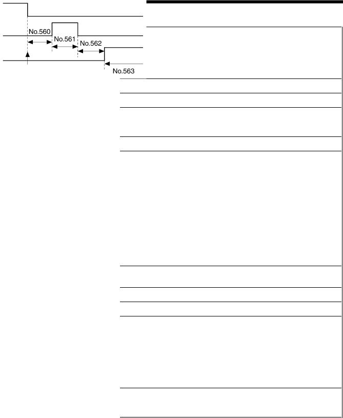
4. FUNCTION SETTINGS (G50 OPERATION PANEL)
Standard device settings (550-)
No. |
Setting |
Initial |
Setting |
|
range |
value |
units |
||
|
||||
550 |
0-1 |
0 |
1 |
|
(*1) |
||||
|
|
|
||
|
|
|
|
|
551 |
0-500 |
150 |
10 |
|
(ms) |
(ms) |
(ms) |
||
|
||||
555 |
-345-345 |
0 |
1 |
|
(degrees) |
(degrees) |
|||
|
|
|||
556 |
-345-345 |
0 |
1 |
|
(degrees) |
(degrees) |
|||
|
|
|||
557 |
-345-345 |
0 |
1 |
|
(degrees) |
(degrees) |
|||
|
|
|||
558 |
-345-345 |
0 |
1 |
|
(degrees) |
(degrees) |
|||
|
|
|||
560 |
10-200 |
20 |
10 |
|
(ms) |
(ms) |
(ms) |
||
|
||||
|
|
|
|
|
561 |
10-200 |
50 |
10 |
|
(ms) |
(ms) |
(ms) |
||
|
||||
|
|
|
|
|
562 |
10-200 |
50 |
10 |
|
(ms) |
(ms) |
(ms) |
||
|
||||
|
|
|
|
|
563 |
10-990 |
300 (ms) |
10 |
|
(ms) |
(ms) |
|||
|
|
|||
564 |
0-240 |
180 |
1 |
|
(seconds) |
(seconds) |
|||
|
|
|||
|
|
|
|
|
565 |
10-60 |
25 |
1 |
|
(%) |
(%) |
|||
|
|
|||
566 |
10-60 |
50 |
1 |
|
(%) |
(%) |
|||
|
|
|||
567 |
0-1 |
0 |
1 |
|
|
|
|
|
|
568 |
20-120 |
40 |
5 |
|
(ms) |
(ms) |
(ms) |
||
|
||||
|
|
|
|
|
569 |
10-12 |
12 |
1 |
|
|
|
|
|
|
573 |
40-100 |
85 |
5 |
|
(ms) |
(ms) |
(ms) |
||
|
||||
574 |
10-60 |
40 |
1 |
|
(%) |
(%) |
|||
|
|
Setting details
Automatic presser foot lifter type
0:Solenoid type
(Duty during chopping can be changed using No. 565.)
1:Pneumatic type
(Duty during chopping can be changed using No. 566.)
Sewing machine motor start delay time when presser foot is raised
Quick reverse solenoid on timing during start backtacking/continuous backtacking
Quick reverse solenoid off timing during start backtacking/continuous backtacking
Quick reverse solenoid off timing during end backtacking
Quick reverse solenoid on timing during end backtacking * This is only enabled when No. 451 is set to “ON”.
Thread wiping and presser foot lift operation timing after thread trimming
Motor
Thread wiping
Presser foot lifting
Needle up stop
2016B
Presser foot lifter solenoid fully ON time
Presser foot lift time
0: No timer function (does not drop) 1-240: Presser foot drops after set time
On duty when solenoid-type presser lifter solenoid is chopping * This is only enabled when No. 550 is set to “0”.
On duty when pneumatic-type presser lifter solenoid is chopping * This is only enabled when No. 550 is set to “1”.
Presser foot soft down mode
0:Automatic mode (This can be adjusted using No. 569.)
1:Manual mode (This must be adjusted using No. 568.)
Delay time for presser foot lifter solenoid to turn on after presser foot drop command
* This is only enabled when No. 567 is set to “1”.
Voltage detection constant for presser foot lifter solenoid to turn on after presser foot drop command
*This is only enabled when No. 567 is set to “0”. If it is set to “10”, the response time will be fastest and the operating sound will be loudest.
Fully on time for quick reverse solenoid
On duty when quick reverse solenoid is chopping
(*1) This is not initialized during initialization mode.
S-7200C |
20 |
4. FUNCTION SETTINGS (G50 OPERATION PANEL)
Error processing settings (650-)
No. |
Setting |
Initial |
Setting |
|
range |
value |
units |
||
|
||||
650 |
OFF/ |
|
|
|
5-30 |
OFF |
1 |
||
|
(seconds) |
|
|
|
651 |
OFF/ |
3 |
|
|
1-30 |
1 |
|||
(minutes) |
||||
|
minutes |
|
||
|
|
|
|
|
652 |
ON/OFF |
ON |
- |
|
|
|
|
|
Setting details
Time until buzzer stops (seconds) OFF: Buzzer does not stop
5-30: Buzzer stops after the specified time
Overtime error display
* If the thread wiper key is OFF, error displays do not appear. OFF: None
1-30: After continuous operation for the set length of time, operation stops and [E190] is displayed.
Needle up stop error display OFF: None
ON: If the needle does not stop at the up position after thread trimming, [E111] is displayed.
Specifications and destination settings (850-)
No. |
Setting |
Initial |
Setting |
|
range |
value |
units |
||
|
851 ON/OFF |
(*1) |
- |
|
852 ON/OFF |
(*1) |
- |
Setting details
Treadle operation specifications
ON: Specifications for Europe and the Americas
If No. 001 is “OFF”
(When the treadle is returned to the neutral position after thread trimming, the presser foot is lowered.)
*If the treadle is returned to the neutral position during thread trimming, the presser foot does not rise.
If No. 001 is “ON”
After thread trimming, the presser foot rises.
The presser foot does not drop even when the treadle is returned to the neutral position.
If No. 001 or No. 002 is “ON”
(Even after the treadle has been depressed to the 1st step and the presser foot has dropped, the presser foot rises when the treadle is returned to the neutral position.)
* If No. 852 and No. 057 are not both “ON” at the same time, the presser foot lowering function at the treadle’s 1st step will be disabled.
OFF: Other specifications
The presser foot does not drop even when the treadle is returned to the neutral position after thread trimming.
When the treadle is depressed backward or the knee switch changes
from ON to OFF, the presser foot drops.
(The presser foot does not rise at the treadle neutral position regardless of the settings for No. 001 and No. 002.)
Presser foot lowering at the forward 1st step ON: Enabled
OFF: Disabled
(*1) This is not initialized during initialization mode.
The initial value varies depending on the destination. For Europe and the Americas, the initial setting is “ON”, and for all other destinations are “OFF”.
21 |
S-7200C |
Loading...