


 Loading...
LK3-B448E |
/ BA-16 INSTRUCTION MANUAL |
Please read this manual before using the machine.
Please keep this manual within easy reach for quick reference.
ELECTRONIC LOCKSTITCH BUTTON SEWER WITH BUTTON FEEDER
Thank you very much for buying a BROTHER sewing machine. Before using your new machine, please read the safety instructions below and the explanations given in the instruction manual.
With industrial sewing machines, it is normal to carry out work while positioned directly in front of moving parts such as the needle and thread take-up lever, and consequently there is always a danger of injury that can be caused by these parts. Follow the instructions from training personnel and instructors regarding safe and correct operation before operating the machine so that you will know how to use the machine correctly.
SAFETY INSTRUCTIONS
zSafety indications and their meanings
This instruction manual and the indications and symbols that are used on the machine itself are provided in order to ensure safe operation of this machine and to prevent accidents and injury to yourself or other people. The meanings of these indications and symbols are given below.
Indications
DANGER |
The instructions which follow this term indicate situations where failure to follow the |
instructions will almost certainly result in death or severe injury. |
|
|
|
CAUTION |
The instructions which follow this term indicate situations where failure to follow the |
instructions could cause injury when using the machine or physical damage to |
|
|
equipment and surroundings. |
|
|
Symbols
............. This symbol ( ) indicates something that you should be careful of. The picture inside the triangle indicates the nature of the caution that must be taken.
(For example, the symbol at left means “beware of injury”.)
............. This symbol ( |
) indicates something that you must not do. |
............. This symbol ( |
) indicates something that you must do. The picture inside the circle |
indicates the nature of the thing that must be done.
(For example, the symbol at left means “you must make the ground connection”.)
LK3-B448E MARKII/BA-16
i
 DANGER
Wait at least 5 minutes after turning off the power switch and disconnecting the power cord from the wall outlet before opening the face plate of the control box. Touching areas where high voltages are present can result in severe injury.
 CAUTION
Environmental requirements
Use the sewing machine in an area which is free from sources of strong electrical noise such as highfrequency welders.
Sources of strong electrical noise may cause problems with correct operation.
Any fluctuations in the power supply voltage should be within ± 10% of the rated voltage for the machine.
Voltage fluctuations which are greater than this may cause problems with correct operation.
The power supply capacity should be greater than the requirements for the sewing machine’s electrical consumption.
Insufficient power supply capacity may cause problems with correct operation.
The ambient temperature should be within the range of 5° C to 35° C during use.
Temperatures which are lower or higher than this may cause problems with correct operation.
The relative humidity should be within the range of 45% to 85% during use, and no dew formation should occur in any devices.
Excessively dry or humid environments and dew formation may cause problems with correct operation.
Avoid exposure to direct sunlight during use.
Exposure to direct sunlight may cause problems with correct operation.
In the event of an electrical storm, turn off the power and disconnect the power cord from the wall outlet.
Lightning may cause problems with correct operation.
Installation
Machine installation should only be carried out by a qualified technician.
Contact your Brother dealer or a qualified electrician for any electrical work that may need to be done.
The sewing machine weighs more than 47 kg. The installation should be carried out by two or more people.
Do not connect the power cord until installation is complete, otherwise the machine may operate if the foot switch is pressed by mistake, which could result in injury.
Hold the machine head with both hands when tilting it back or returning it to its original position. Furthmore, after tilring back the machine head, do not push the face plate side or the pulley side from above, as this could cause the machine head to topple over, which may result in personal injury or damage to the machine.
Be sure to connect the ground. If the ground connection is not secure, you run a high risk of receiving a serious electric shock, and problems with correct operation may also occur.
All cords should be secured at least 25 mm away from any moving parts. Furthermore, do not excessively bend the cords or secure them too firmly with staples, otherwise there is the danger that fire or electric shocks could occur.
Install the belt covers to the machine head and motor.
If using a work table which has casters, the casters should be secured in such a way so that they cannot move.
Be sure to wear protective goggles and gloves when handling the lubricating oil and grease, so that they do not get into your eyes or onto your skin, otherwise inflammation can result.
Furthermore, do not drink the oil or eat the grease under any circumstances, as they can cause vomiting and diarrhoea.
Keep the oil out of the reach of children.
LK3-B448E MARKII/BA-16
ii
 CAUTION
Sewing
This sewing machine should only be used by operators who have received the necessary training in safe use beforehand.
The sewing machine should not be used for any applications other than sewing.
Be sure to wear protective goggles when using the machine.
If goggles are not worn, there is the danger that if a needle breaks, parts of the broken needle may enter your eyes and injury may result.
Set the needle to the needle up stop position before turning on the power.
If this is not done, the wiper may strike the needle, which might cause the needle to break.
Turn off the power switch at the following times, otherwise the machine may operate if the foot switch is pressed by mistake, which could result in injury.
•When threading the needle
•When replacing the needle and bobbin
•When not using the machine and when leaving the machine unattended
If using a work table which has casters, the casters should be secured in such a way so that they cannot move.
Attach all safety devices before using the sewing machine. If the machine is used without these devices attached, injury may result.
Do not touch any of the moving parts or press any objects against the machine while sewing, as this may result in personal injury or damage to the machine.
If an error occurs in machine, or if abnormal noises or smells are noticed, immediately turn off the power switch. Then contact your nearest Brother dealer or a qualified technician.
If the machine develops a problem, contact your nearest Brother dealer or a qualified technician.
Cleaning
Set the needle to the needle up stop position before turning on the power.
If this is not done, the wiper may strike the needle, which might cause the needle to break.
Turn off the power switch before carrying out cleaning, otherwise the machine may operate if the foot switch is pressed by mistake, which could result in injury.
Be sure to wear protective goggles and gloves when handling the lubricating oil and grease, so that they do not get into your eyes or onto your skin, otherwise inflammation can result.
Furthermore, do not drink the oil or eat the grease under any circumstances, as they can cause vomiting and diarrhoea.
Keep the oil out of the reach of children.
Maintenance and inspection
Maintenance and inspection of the sewing machine should only be carried out by a qualified technician.
Ask your Brother dealer or a qualified electrician to carry out any maintenance and inspection of the electrical system.
Set the needle to the needle up stop position before turning on the power.
If this is not done, the wiper may strike the needle, which might cause the needle to break.
Turn off the power switch and disconnect the power cord from the wall outlet at the following times, otherwise the machine may operate if the foot switch is pressed by mistake, which could result in injury.
•When carrying out inspection, adjustment and maintenance
•When replacing consumable parts such as the rotary hook
If the power switch needs to be left on when carrying out some adjustment, be extremely careful to observe all safety precautions.
Hold the machine head with both hands when tilting it back or returning it to its original position. Furthermore, after tilting back the machine head, do not push the face plate side or the pulley side from above, as this could cause the machine head to topple over, which may result in personal injury or damage to the machine.
Use only the proper replacement parts as specified by Brother.
If any safety devices have been removed, be absolutely sure to re-install them to their original positions and check that they operate correctly before using the machine.
Any problems in machine operation which result from unauthorized modifications to the machine will not be covered by the warranty.
LK3-B448E MARKII/BA-16
iii

cWarning labels
The following warning labels appear on the sewing machine.
Please follow the instructions on the labels at all times when using the machine. If the labels have been removed or are difficult to read, please contact your nearest Brother dealer.
1
Hazardous voltage will cause injury.
Turn off main switch and wait 5 minutes before opening this cover.
Hochspannung verletzungsgefahr! Bitte schalten sie den hauptschalter aus und warten sie 5 minuten, bevor sie diese abdeckung ffnen.
Un voltage non adapt provoque des blessures.
Eteindrel’interrupteur et attendre 5 minutes avantd’ ouvrir le capot
Un voltaje inadecuado puede provocar las heridas.
Apagar el interruptor principal y esperar 5 minutos antes de abrir esta cubierta.
2 |
CAUTION |
|
Moving parts may cause injury.
Operate with safety devices. Turn off main switch before threading, changing bobbin and needle, cleaning etc.
Safety devices: qBelt cover,
wThread take-up cover, eEye guard,
rMotor cover,
tThread take-up solenoid cover, etc.
4 
w
t
e
2
r
3
4
Be sure to connect the ground.
If the ground connection is not secure, you run the risk of receiving a serious electric shock.
Direction of operation
q
3
1
1
LK3-B448E MARKII/BA-16
iv
CONTENTS |
|
1. Name of each part ................................................................................................................. |
1 |
2. Specifications .......................................................................................................................... |
2 |
2-1. Specifications .............................................................................................................................. |
2 |
2-2. Program list ................................................................................................................................. |
3 |
2-3. Optional parts.............................................................................................................................. |
6 |
3. Installation .................................................................................................................................. |
7 |
3-1. Power table ................................................................................................................................. |
7 |
3-2. Installing the motor ...................................................................................................................... |
8 |
3-3. Installing the motor pulley ........................................................................................................... |
8 |
3-4. Installing the control box ............................................................................................................. |
9 |
3-5. Installing the oil pan .................................................................................................................. |
10 |
3-6. Installing the cushions............................................................................................................... |
10 |
3-7. Installing the machine head ....................................................................................................... |
11 |
3-8. Installing the head rest ............................................................................................................... |
11 |
3-9. Installing the liquid cooling tank, optional.................................................................................. |
12 |
3-10. Installing the vibrating bowl ..................................................................................................... |
12 |
3-11. Installing the control box (for vibrating bowl) ........................................................................... |
12 |
3-12. Installing the button feeder...................................................................................................... |
13 |
3-13. Installing the shooter ............................................................................................................... |
13 |
3-14. Connecting the cords .............................................................................................................. |
14 |
3-15. Installing the button feeder cover ............................................................................................ |
16 |
3-16. Installing the operation panel .................................................................................................. |
17 |
3-17. Connecting the ground wire .................................................................................................... |
17 |
3-18. Installing the V-belt.................................................................................................................. |
18 |
3-19. Installing the belt cover ........................................................................................................... |
19 |
3-20. Installing the foot switch .......................................................................................................... |
19 |
3-21. Installing the motor cover ........................................................................................................ |
20 |
3-22. Installing the spool stand ........................................................................................................ |
20 |
3-23. Installing the eye guard ........................................................................................................... |
20 |
3-24. Adjustment by the accessory spring ....................................................................................... |
21 |
4. Lubrication ................................................................................................................................ |
22 |
4-1. Lubrication points ...................................................................................................................... |
22 |
4-2. Applying grease ........................................................................................................................ |
23 |
4-3. Draining the oil .......................................................................................................................... |
23 |
5. Operation ................................................................................................................................... |
24 |
5-1. Name and function of each operation panel item ..................................................................... |
24 |
5-2. Operating procedure ................................................................................................................. |
26 |
5-2-1 . Setting the program number ........................................................................................... |
26 |
5-2-2 . Setting the X-scale and Y-scale ...................................................................................... |
26 |
5-2-3 . Setting the sewing speed................................................................................................ |
26 |
5-3. Operating the button feeder ...................................................................................................... |
27 |
5-4. Operating the vibrating bowl ..................................................................................................... |
27 |
6. Checking the sewing pattern ........................................................................................ |
28 |
7. Correct use ............................................................................................................................... |
29 |
7-1. Selecting the needle and thread ............................................................................................... |
29 |
7-2. Installing the needle .................................................................................................................. |
29 |
7-3. Threading the upper thread ...................................................................................................... |
29 |
7-4. Winding the lower thread .......................................................................................................... |
30 |
7-5. Replacing the bobbin case and threading the thread ............................................................... |
31 |
7-6. Thread tension reference guide ................................................................................................ |
31 |
7-6-1. Lower thread tension ....................................................................................................... |
31 |
7-6-2. Upper thread tension ....................................................................................................... |
31 |
7-6-3. Thread take-up spring height ........................................................................................... |
32 |
7-6-4. Thread take-up spring tension ......................................................................................... |
32 |
7-6-5. Adjusting arm thread guide R .......................................................................................... |
32 |
7-6-6. Thread take-up amount ................................................................................................... |
32 |
LK3-B448E MARKII/BA-16
8. Sewing ......................................................................................................................................... |
33 |
9. Maintenance and inspection.......................................................................................... |
34 |
9-1. Cleaning the rotary hook ........................................................................................................... |
34 |
9-2. Cleaning the control box air inlet port ....................................................................................... |
34 |
9-3. Cleaning the eye guard ............................................................................................................. |
35 |
9-4. Checking the needle ................................................................................................................. |
35 |
10. Adjustments .......................................................................................................................... |
36 |
10-1. Adjusting the needle bar height............................................................................................... |
37 |
10-2. Adjusting the needle bar lift amount ........................................................................................ |
37 |
10-3. Adjusting the driver needle guard ........................................................................................... |
38 |
10-4. Adjusting the needle clearance ............................................................................................... |
38 |
10-5. Adjusting the shuttle race thread guide ................................................................................... |
38 |
10-6. Adjusting the thread take-up amount ...................................................................................... |
39 |
10-7. Adjusting the movable knife .................................................................................................... |
39 |
10-7-1. Replacing the movable knife and fixed knife ................................................................. |
40 |
10-7-2. Adjustment the engagement of the movable knife and fixed knife................................. |
41 |
10-8. Adjusting the button clamp lift amount .................................................................................... |
41 |
10-9. Adjusting the holding pressure ................................................................................................ |
42 |
10-10. Adjusting the position of the button holder ............................................................................ |
42 |
10-11. Adjusting the button clamp height ......................................................................................... |
43 |
10-12. Adjusting the needle up stop position ................................................................................... |
44 |
10-13. Adjusting the thread wiper ..................................................................................................... |
44 |
10-14. Adjusting the vibrating bowl .................................................................................................. |
45 |
10-15. Adjustment for excess buttons in the button shooter ............................................................ |
46 |
10-16. Button replacement ............................................................................................................... |
47 |
10-16-1. Adjustment when the button diamenter is changed ..................................................... |
47 |
10-16-2. Adjustment when the button thickness changed.......................................................... |
48 |
10-16-3. If button hole arrangements differ ................................................................................ |
48 |
10-16-4. Adjusting the button carrier plate ................................................................................. |
48 |
10-16-5. Adjusting the feeder position adjustment ..................................................................... |
49 |
10-16-6. Adjusting the needle location ....................................................................................... |
50 |
10-17. Replacement the V-belt......................................................................................................... |
51 |
10-18. Checking the input sensor and DIP switch input ................................................................... |
53 |
10-19. Checking the input voltage .................................................................................................... |
54 |
10-20. Moving stitch patterns ........................................................................................................... |
55 |
11. Using the counters ............................................................................................................ |
56 |
11-1. Using the bobbin thread counter ............................................................................................. |
56 |
11-2. Using the production counter .................................................................................................. |
56 |
12. Using user programs ....................................................................................................... |
57 |
13. Using the cycle sewing function .............................................................................. |
59 |
14. Changing functions using the DIP switches..................................................... |
61 |
14-1. Operation panel DIP switches ................................................................................................. |
61 |
14-2. Setting the presser mode ........................................................................................................ |
61 |
14-3. DIP switches inside the control box ........................................................................................ |
62 |
15. Changing special functions using the memory switches......................... |
63 |
15-1. Clearing all memory settings ................................................................................................... |
63 |
16. Table of error codes ......................................................................................................... |
65 |
17. Adjustment guide refer to this guide |
|
when different button are used ................................................................................. |
67 |
18. Troubleshooting.................................................................................................................. |
68 |
LK3-B448E MARKII/BA-16
1.Name of each part
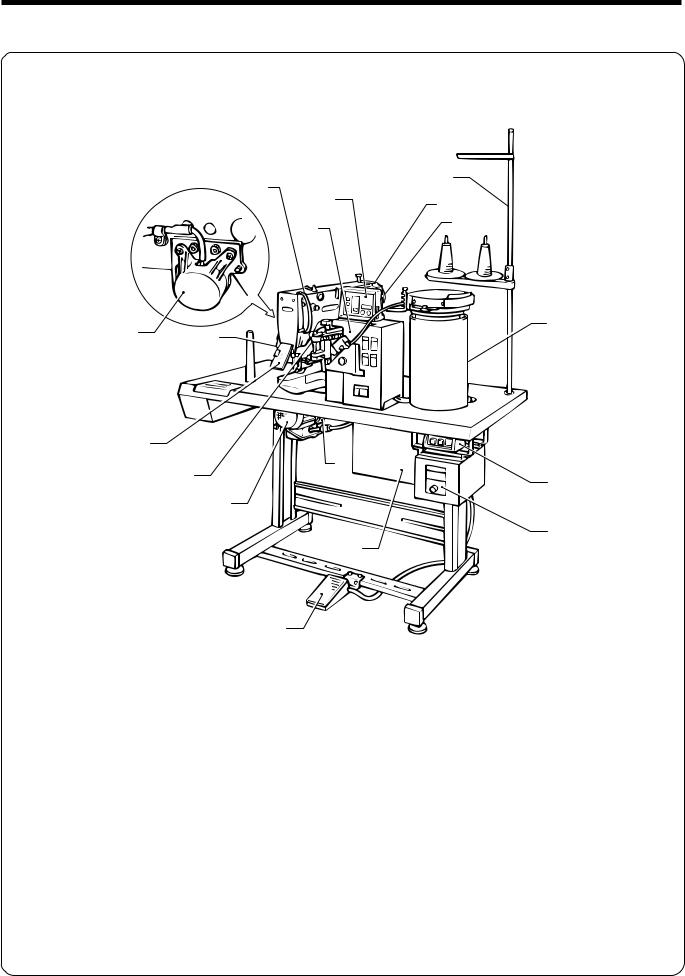
1. Name of each part
i
!4
e!5
!0 u
!7 |
!1 |
|
y |
||
|
!3
o |
!6 |
|
q |
||
|
||
|
t |
|
|
!2 |
|
|
w |
r
qPower switch |
wControl box |
eOperation panel |
rFoot switch |
tMotor |
yTension release lever |
uPulley |
iSpool stand |
oThread take-up lever |
!0Button feeder |
!1Vibrating bowl |
!2Control box |
!3Eye guard |
!4Thread take-up cove |
!5Belt cover |
!6Motor cover |
!7Thread take-up solenoid |
|
|
|
LK3-B448E MARKII/BA-16
1

2. Specifications
2. Specifications
2-1. Specifications
|
Stitch formation |
|
Single needle lock stitch |
|
|
Maximum sewing |
|
2,500 rpm |
|
|
speed |
|
||
|
|
|
|
|
|
Maximum pattern size |
|
0 - 6.4 0 - 6.4 mm |
|
|
|
|
||
|
Needle |
|
TQ 1#12 |
|
|
Dimensions of buttons |
|
Outer diameter of button 9 - 22 mm |
|
|
that can be sewn |
|
||
|
|
Space between the button holes 2.5 - 6.4 mm |
||
|
|
|
||
|
Button clamp height |
|
10 mm (standard) |
|
|
Thread knot |
|
Knot tied by needle |
|
|
Feed mechanism |
|
R-θ intermittent feed mechanism (pulse-motor driven mechanism) |
|
|
Stitch length |
|
0.1 - 6.4 mm |
|
|
Number of stitches |
|
Variable (13, 15, 17, 19, 20, 22, 23, 24, 26, 27, 28, 30, 32, 34, 38 stitches |
|
|
|
pre-set) |
||
|
|
|
||
|
Maximum stitch |
|
20,000 stitches (including 10,000 stitches which can be added) |
|
|
number |
|
||
|
|
|
|
|
|
Work clamp lifter |
|
Solenoid type |
|
|
Rotary hook |
|
Shuttle hook |
|
|
Wiper device |
|
Standard equipment. (Solenoid-type thread wiper (Option) |
|
|
Thread trimmer device |
|
Standard equipment |
|
|
|
|
||
|
|
|
|
|
|
|
|
|
|
|
Thread take-up device |
|
Standard equipment |
|
|
Data storage method |
|
P-ROM (Any sewing pattern can be added using BAS-PC/300.) |
|
|
Number of user |
16 |
|
|
|
programs |
|
||
|
|
|
|
|
|
|
|
|
|
|
Number of cycle |
|
4 |
|
|
programs |
|
|
|
|
|
|
|
|
|
|
|
|
|
|
Number of stored data |
|
49 sewing patterns are set already. |
|
|
|
(Up to 100 patterns can be added. Total number of stitches of stored data |
||
|
|
|
||
|
|
|
which can be added is within 10,000.) |
|
Motor
Weights
Power source
Three-phase 400W induction motor
Machine head: 47kg, Operation panel: 0.6kg, Control box: 9 - 19kg (depending on destination)
Single-phase 220 - 230V 3-phase 220, 380, 400, 415V
Maximum electric power consumption; 600VA
LK3-B448E MARKII/BA-16
2

2. Specifications
2-2. Program list
Sewing patterns are limited as shown in the table below.
(Any program is available as long as the needle drops down in the hole of the button.)
|
No. of |
Sewing |
No. of |
No. of |
No. of |
Standard |
Standard |
||||
Program No. |
crossover |
||||||||||
button holes |
pattern |
threads |
stitches |
sewing length X |
sewing width Y |
||||||
|
stitches |
||||||||||
|
|
|
|
|
|
|
|
|
|
||
1 |
|
|
|
|
|
6 |
__ |
13 |
|
|
|
|
|
|
|
|
|
|
|
||||
|
|
|
|
|
|
|
|
|
|
|
|
2 |
|
|
|
|
|
8 |
__ |
15 |
|
|
|
|
|
|
|
|
|
|
|
||||
|
|
|
|
|
|
|
|
|
|
|
|
3 |
|
|
|
|
|
10 |
__ |
17 |
|
|
|
|
|
|
|
|
|
|
|
||||
|
|
|
|
|
|
|
|
|
3.4mm |
0mm |
|
4 |
|
|
|
|
|
12 |
__ |
19 |
|||
|
|
|
|
|
|
|
|||||
|
|
|
|
|
|
|
|
||||
|
|
|
|
|
|
|
|
|
|
|
|
*1 |
2 |
|
|
|
|
16 |
__ |
23 |
|
|
|
5 |
|
|
|
|
|
|
|
||||
|
|
|
|
|
|
|
|
|
|
|
|
*1 |
|
|
|
|
|
20 |
__ |
27 |
|
|
|
6 |
|
|
|
|
|
|
|
|
|||
|
|
|
|
|
|
|
|
|
|
|
|
*2 |
|
|
|
|
|
6 |
__ |
13 |
|
|
|
7 |
|
|
|
|
|
|
|
|
|||
|
|
|
|
|
|
|
|
|
|
|
|
*2 |
|
|
|
|
|
10 |
__ |
17 |
0mm |
3.4mm |
|
23 |
|
|
|
|
|
|
|||||
|
|
|
|
|
|
|
|
|
|
|
|
*2 |
|
|
|
|
|
12 |
__ |
19 |
|
|
|
8 |
|
|
|
|
|
|
|
|
|||
|
|
|
|
|
|
|
|
|
|
|
|
*2 |
|
|
|
|
|
5-5-5 |
__ |
22 |
|
|
|
9 |
|
|
|
|
|
|
|
|
|||
|
|
|
|
|
|
|
|
|
|
|
|
*2 |
|
|
|
|
|
7-7-7 |
__ |
28 |
|
|
|
24 |
|
|
|
|
|
|
|
|
|||
|
3 |
|
|
|
|
|
|
|
2.6mm |
2.4mm |
|
*2 |
|
|
|
|
5-5-5 |
__ |
22 |
||||
|
|
|
|
|
|
|
|||||
25 |
|
|
|
|
|
|
|
|
|||
|
|
|
|
|
|
|
|
|
|
|
|
*2 |
|
|
|
|
|
7-7-7 |
__ |
28 |
|
|
|
26 |
|
|
|
|
|
|
|
|
|||
|
|
|
|
|
|
|
|
|
|
|
|
*2 |
|
|
|
|
|
6-6 |
1 |
20 |
|
|
|
10 |
|
|
|
|
|
|
|
||||
|
|
|
|
|
|
|
|
|
|
|
|
*2 |
|
|
|
|
|
8-8 |
1 |
24 |
|
|
|
11 |
|
|
|
|
|
|
|
||||
|
|
|
|
|
|
|
|
|
|
|
|
*2 |
4 |
|
|
|
|
|
|
|
|
|
|
12 |
|
|
|
|
8-8 |
3 |
26 |
|
|
||
|
|
|
|
|
|
||||||
|
|
|
|
|
|
|
|
|
|
|
|
*2 |
|
|
|
|
|
10-10 |
1 |
28 |
|
|
|
13 |
|
|
|
|
|
|
|
||||
|
|
|
|
|
|
|
|
|
|
|
|
*2 |
|
|
|
|
|
12-12 |
1 |
32 |
3.4mm |
3.4mm |
|
27 |
|
|
|
|
|
||||||
|
|
|
|
|
|
|
|
|
|
|
|
*3 |
|
|
|
|
|
6-6 |
0 |
26 |
|
|
|
14 |
|
|
|
|
|
|
|
||||
|
|
|
|
|
|
|
|
|
|
|
|
*3 |
|
|
|
|
|
8-8 |
0 |
30 |
|
|
|
28 |
|
|
|
|
|
|
|
||||
|
4 |
|
|
|
|
|
|
|
|
|
|
*3 |
|
|
|
|
10-10 |
0 |
34 |
|
|
||
|
|
|
|
|
|
|
|||||
15 |
|
|
|
|
|
|
|
||||
|
|
|
|
|
|
|
|
|
|
|
|
*3 |
|
|
|
|
|
12-12 |
0 |
38 |
|
|
|
29 |
|
|
|
|
|
|
|
||||
|
|
|
|
|
|
|
|
|
|
|
|
LK3-B448E MARKII/BA-16
3
2. Specifications
|
No. of |
Sewing |
No. of |
No. of |
No. of |
Standard |
Standard |
|
Program No. |
crossover |
|||||||
button holes |
pattern |
threads |
stitches |
sewing length X |
sewing width Y |
|||
|
stitches |
|||||||
|
|
|
|
|
|
|
||
16 |
|
|
6-5 |
1 |
19 |
|
|
|
17 |
|
|
8-7 |
1 |
23 |
|
|
|
30 |
|
|
10-9 |
1 |
27 |
|
|
|
*2 |
|
|
6-6 |
1 |
20 |
|
|
|
18 |
|
|
|
|
||||
*2 |
|
|
8-8 |
1 |
24 |
|
|
|
19 |
|
|
|
|
||||
*2 |
|
|
|
|
|
3.4mm |
3.4mm |
|
|
|
10-10 |
1 |
28 |
|
|
||
31 |
|
|
|
|
||||
*2 |
|
|
12-12 |
1 |
32 |
|
|
|
45 |
|
|
|
|
||||
*3 |
|
|
6-6 |
0 |
26 |
|
|
|
20 |
|
|
|
|
||||
*3 |
|
|
8-8 |
0 |
30 |
|
|
|
32 |
|
|
|
|
||||
*3 |
4 |
|
|
|
|
|
|
|
|
|
10-10 |
0 |
34 |
|
|
||
33 |
|
|
|
|
||||
*2 |
|
|
6-6 |
1 |
20 |
|
|
|
21 |
|
|
|
|
||||
*2 |
|
|
10-10 |
1 |
28 |
|
|
|
34 |
|
|
|
|
||||
*2*3 |
|
|
|
|
|
2.4mm |
3.4mm |
|
|
|
6-6 |
0 |
26 |
|
|
||
22 |
|
|
|
|
||||
|
|
|
|
|
|
|
||
*2*3 |
|
|
10-10 |
0 |
34 |
|
|
|
35 |
|
|
|
|
||||
|
|
|
|
|
|
|
||
46 |
|
|
6-6 |
1 |
20 |
|
|
|
47 |
|
|
8-8 |
1 |
24 |
|
|
|
|
|
|
|
|
|
3.4mm |
3.4mm |
|
48 |
|
|
10-10 |
1 |
28 |
|
|
|
49 |
|
|
12-12 |
1 |
32 |
|
|
*1 Check that the button hole diameter is 2 mm or greater before using the programs. *2 Do not use the button lifter spring.
*3 the presser foot lifts up once and the wiper operates, and then the other side is sewn, because there is no crossover thread to be sewn. (Operation will be different if the optional solenoid-type thread wiper is installed. [Refer to page 5].)
•If you want to sew a pattern other than one of the standard 24 patterns, you can create your original pattern using the BAS-PC/300.
Consult with your local Brother Sales Office for details.
LK3-B448E MARKII/BA-16
4

2. Specifications
|
No. of |
Sewing |
No. of |
No. of |
No. of |
Standard |
Standard |
|
Program No. |
crossover |
|||||||
button holes |
pattern |
threads |
stitches |
sewing length X |
sewing width Y |
|||
|
stitches |
|||||||
|
|
|
|
|
|
|
||
36 |
|
|
6-6 |
0 |
26 |
|
|
|
37 |
|
|
8-8 |
0 |
30 |
|
|
|
38 |
|
|
10-10 |
0 |
34 |
|
|
|
39 |
|
|
12-12 |
0 |
38 |
3.4mm |
3.4mm |
|
40 |
4 |
|
6-6 |
0 |
26 |
|
|
|
41 |
|
|
8-8 |
0 |
30 |
|
|
|
42 |
|
|
10-10 |
0 |
34 |
|
|
|
* |
|
|
6-6 |
0 |
26 |
|
|
|
43 |
|
|
|
|
||||
* |
|
|
|
|
|
2.4mm |
3.4mm |
|
|
|
10-10 |
0 |
34 |
|
|
||
44 |
|
|
|
|
||||
*2 Do not use the button lifter spring. |
|
|
|
|
|
|||
LK3-B448E MARKII/BA-16
5

2. Specifications
2-3. Optional parts
■ Liquid cooling tank
■ Two-pedal foot switch
■ Solenoid-type thread wiper
■Button spacer set
#S09661-001
This helps to prevent thread breakages caused by friction when using synthetic threads.
Fill the tank with silicone oil (100 mm2/s).
The switch has an independent presser switch (left side) and start switch (right side).
When sewing without crossover threads (program Nos 14, 15, 20 and 22, 28, 29 and 32, 33, 35), do not move the button clamp assembly vertically while sewing is in pro-gress. (Refer to “Changing special functions using the memory switches” on page 59 “memo 14”.)
For men’s garments |
For women’s garments |
LK3-B448E MARKII/BA-16
6
3. Installation
3. Installation
 CAUTION
Machine installation should only be carried out by a qualified technician.
Contact your Brother dealer or a qualified electrician for any electrical work that may need to
be done.
The sewing machine head weighs more than 47 kg. The installation should be carried out by two or more people.
Do not connect the power cord until installation is complete, otherwise the machine may operate if the foot switch is depressed by mistake, which could result in injury.
Hold the machine head with both hands when tilting it back or returning it to its original position. Furthermore, after tilting back the machine head, do not push the face plate side or the pulley side from above, as this could cause
the machine head to topple over, which may
result in personal injury or damage to the machine.
All cords should be secured at least 25 mm away from any moving parts. Furthermore, do not excessively bend the cable or secure it too firmly staples, otherwise there is the danger that fire or electric shocks could occur.
Be sure to connect the ground. If the ground connection is not secure, you run the risk of receiving a serious electric shock.
Install the belt covers to the machine head and motor.
Avoid setting up the sewing machine near sources of strong electrical noise such as highfrequency welding equipment.
If this precaution is not taken, incorrect machine operation may result.
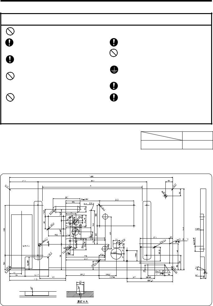
3-1. Power table
• Use the power table which has been specially designed for the B448E.
* If using a commercially-available table, process it as shown in the illustration below.
NOTE: The thickness of the table should be at least 40 mm, and it should be strong enough to bear the weight and vibration of the sewing machine.
If the distance A between the insides of the legs is less than 740 mm, move the control box installation position closer to the motor (B=247 mm).
LK3-B448E MARKII/BA-16
7
3. Installation
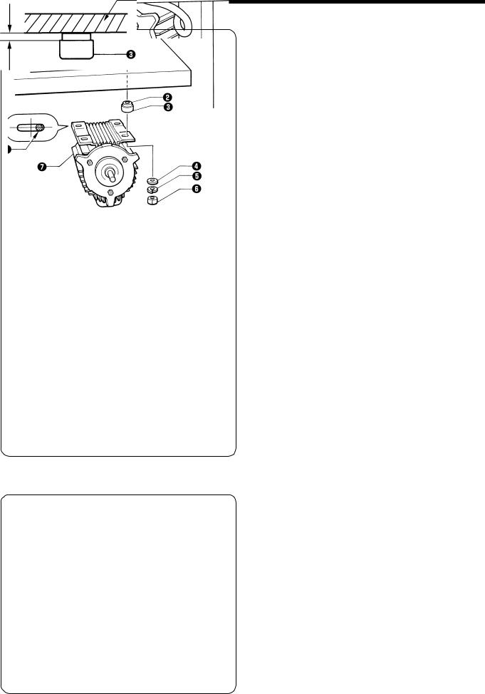
3-2. Installing the motor
Install the motor u to the work table with the four accessory bolts q, cushions w, cushion collars e, flat washers r, spring washers t and nuts y.
At that time, fix by setting bolts q a little to the right of oval hole on motor.
NOTE:
Tighten the nuts so that the clearance between the table and the cushion collars is approximately 1 mm.
Table
1 mm
3-3. Installing the motor pulley
Place the motor pulley q onto the shaft of the motor w so that the key groove is aligned, and then tighten the set screw e so that the center of the V groove in the motor pulley q is aligned as closely as possible with the center of the belt hole in the power table.
LK3-B448E MARKII/BA-16
8
3. Installation
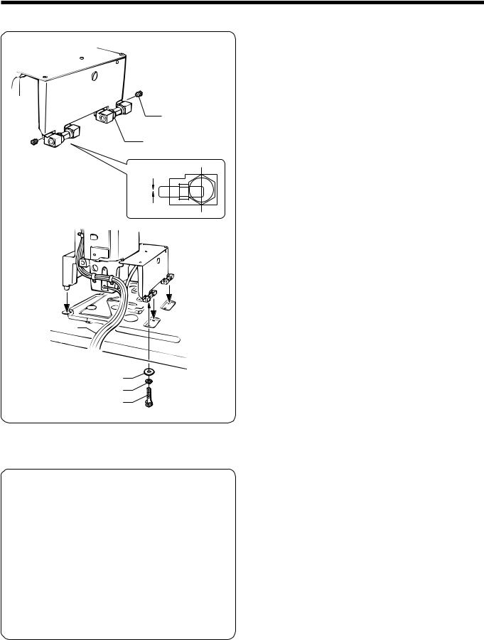
3-4. Installing the control box
Table
Cushions
Cushion collars
3 mm
Rubber collars
Flat washers
Nuts
1.Remove the 12 screws q, and then open the covers (panel mounting assembly w and main P.C. board mounting plate e).
NOTE:
When opening the cover, hold it securely so that it does not fall down.
2.Install the control box with the four accessory bolts r, cushions t, cushion collars y, rubber collars u, flat washers i and nuts o as shown in the illustration above. At this time, leave a gap of approximately 3 mm between the work table and the top of the box.
*Use two nuts o at each installation location, and make sure that both nuts are tightened.
3.Close the covers (panel mounting assembly w and main P.C. board mounting plate e), and tighten them with the screws q.
*The main P.C. board mounting plate e will be opened again during “3-13. Connecting the cords”, so provisionally tighten it with the screw q.
4.Install the power switch !0with the two screws !1.
5.Secure the power switch cord with the three staples !2.
6.Pass the motor cord through the cord hole !3.
LK3-B448E MARKII/BA-16
9
3. Installation
3-5. Installing the oil pan
1. Insert the tabs of the oil pan w into the holes for the cushions q, and then secure it in place with the five nails e so that the oil pan w is not at an angle.
2. While pushing the oil pan w down from above, screw in the oil container r.
3-6. Installing the cushions
e
w
1.Place the washers q and cushions w into the two holes in the work table.
*Adjust the height of the machine head to the button feeder by the number of the washers q.
2.After the height is decided, secure them with the nails e.
q
LK3-B448E MARKII/BA-16
10
3. Installation
3-7. Installing the machine head
w
q
1 mm 
e
r t y
1.Insert the two hinge assemblies q into the machine head so that they are parallel, and then secure them with the two set screw w.
2.Place the machine head gently on the table.
NOTE: Pull the cords eout as shown in the illustration above in order to prevent them from being clamped by the machine head.
3.Secure the two hinge assemblies q with the washers r, the spring washers t, and the bolts y, and install the machine head.
3-8. Installing the head rest
Tap the head rest q into the table hole.
NOTE:
Tap the head rest securely into the table hole.
LK3-B448E MARKII/BA-16
11

3. Installation
3-9. Installing the liquid cooling tank, optional
1. Remove the rubber plug, and then push the liquid cooling tank q.
2. Tighten it with the set screw w.
3-10. Installing the vibrating bowl
1. Install the vibration bowl q with bolts w, spring washers e, and washers r.
2. Pass the wires from the vibration bowl q through the hole in the table.
3-11. Installing the control box (for vibrating bowl)
1. Mount the control box q to the bottom of the box stay e with screws w.
2. Mount the control box stay e to the bottom of the work table with wood screws r.
LK3-B448E MARKII/BA-16
12
3. Installation
3-12. Installing the button feeder
1. Move button feeder base q to the front and rear and left and right as necessary to install it by using hole bolts w, spring washers e and washers r.
(And install ground wires ty.)
To vibrating bowl To control box
(For vibrating bowl)
3-13. Installing the shooter
1. Raise the shooter lock pin w on the vibrating bowl q, and secure the shooter e by inserting the pin w, through the notch in the shooter.
2. Secure the shooter e with thumb screw r on button feeder t.
LK3-B448E MARKII/BA-16
13
3. Installation
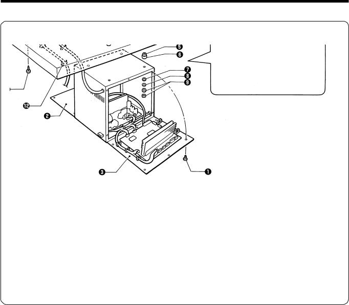
3-14. Connecting the cords
P8
P1
P2
P3
|
|
|
|
P4 |
|
|
|
|
|
P5 |
|
|
|
|
|
P6 |
|
|
|
P11 |
|
P7 |
|
|
|
|
|
|
|
Machine head connectors |
|
Connection location on circuit board |
|||
|
|
|
|||
Connection location |
No. of pins |
Cord mark |
|||
|
|
||||
|
|
|
|
|
|
X, Y, Sewing sensor |
12-pin |
z |
P1 |
(ORG2) |
|
|
|
|
|
|
|
Synchronizer |
5-pin |
x |
P2 |
(SYNCHRO) |
|
|
|
|
|
|
|
Machine specification |
8-pin |
c |
P3 |
(SELECT) |
|
select connector |
|||||
|
|
|
|
||
|
|
|
|
|
|
Thread take-up solenoid |
5-pin |
v |
P4 |
(SOL2) |
|
|
|
|
|
|
|
Presser solenoid |
4-pin |
b |
P5 |
(SOL) |
|
Thread trimmer solenoid |
|||||
|
|
|
|
||
Pulse motor, Y |
4-pin (blue) |
n |
P6 |
(YPM) |
|
|
|
|
|
|
|
Pulse motor, X |
4-pin |
m |
P7 |
(XPM) |
|
|
|
|
|
|
|
Operation panel |
26-pin |
None |
P8 |
(PANEL) |
|
|
|
|
|
||
Upper shaft motor |
3-pin |
None |
P11 (UVW) |
||
|
|
|
|
||
BA16 |
1-pin |
None |
P14 |
||
|
|
|
|
||
BA16 |
16-pin |
None |
P15 |
||
|
|
|
|
|
|
1.Gently tilt back the machine head.
NOTE:
After tilting back the machine head, do not push the face side or the pulley side from above.
2.Pass the cords q through the hole w in the work table.
3.Gently return the machine head to its original position.
4.Remove the six screws e, and then open the control box cover (main P.C. board mounting plate r).
NOTE:
When opening the cover, hold it securely so that it does not fall down.
5.Loosen the two screws t, and then open the cord presser plate y in the direction of the white arrow and pass the cords q through the opening.
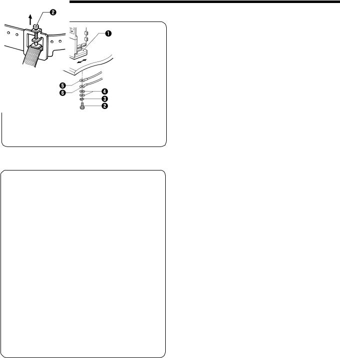
6.Loosen the screw o, and then attach the ground cord u for the machine head and the ground cord i for the operation panel as shown in the illustration.
7.Loosen the screw !1, and then attach the ground cord !0for the upper shaft motor as shown in the illustration.
8.Securely connect connectors P1 to P8 and P11 as indicated in the table.
9.Secure the cords q with the cord clamps !2and !3.
10.Close the cord presser plate y in the direction of the black arrow, and secure it by tightening the screws t.
NOTE:
Check that the cords do not get pulled when the machine head is tilted back gently. 11.Tighten the cover (main P.C. board mounting plate r) with the six screws e.
LK3-B448E MARKII/BA-16
14
3. Installation
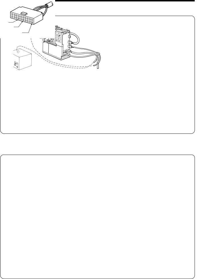
■Button feeder connection
Pull on the connector to make sure it will not come disconnected after connecting the pins.
20P connector
control box
Button feed |
6P |
Red |
|
|
sensor |
|
White |
|
|
|
|
9P |
|
|
|
7P |
Black |
|
|
|
|
|
|
|
|
20P |
|
|
|
|
|
7P connector |
|
|
6P connector |
9P connector |
|
control box |
|
|
(for vibrating bowl) |
|||
Botton stopper solenoid |
(machine head) |
Button feeder switch |
|
|
White |
White |
|
|
|
Black |
|
|
|
|
|
|
|
|
|
|
Red |
|
|
|
|
|
Black Red |
Brown |
Blue |
|
|
White Green |
|
|
Yellow
■Control box (for vibrating bowl) connection
Connect the ground wire from the vibrating bowl to the motor.
9P connector |
2P connector |
Red White Black |
|
Green |
Black |
|
White |
||
|
||
Brown Yellow Blue |
|
|
3P connector (male) |
9P connector (female) |
Black
Green/ White
Yellow
LK3-B448E MARKII/BA-16
15
3.Installation
■Power switch connection
Power switch connector (control box)
|
|
Control box |
|
|
(for vibrating |
|
|
Green/Yerrow |
B |
|
Black |
|
White |
|
|
A |
|
|
Red |
|
|
|
|
|
|
Control box |
|
|
side A |
|
|
Green/Yerrow |
|
|
Black |
|
|
White |
|
|
Red |
|
|
Control box |
|
|
side B |
|
|
Green/Yerrow |
|
|
Red |
|
|
White |
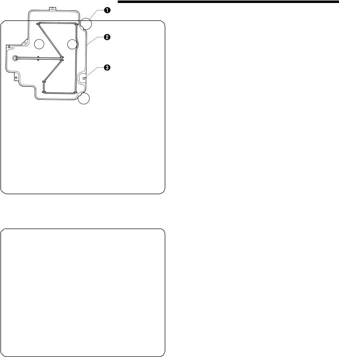
3-15. Installing the button feeder cover
Attach the button feeder cover q to the button feeder w with screws e, spring washers r, and washers t.
* Be sure to pass the wires through the hole in the cover when attaching the button feeder cover q.
LK3-B448E MARKII/BA-16
16
3. Installation
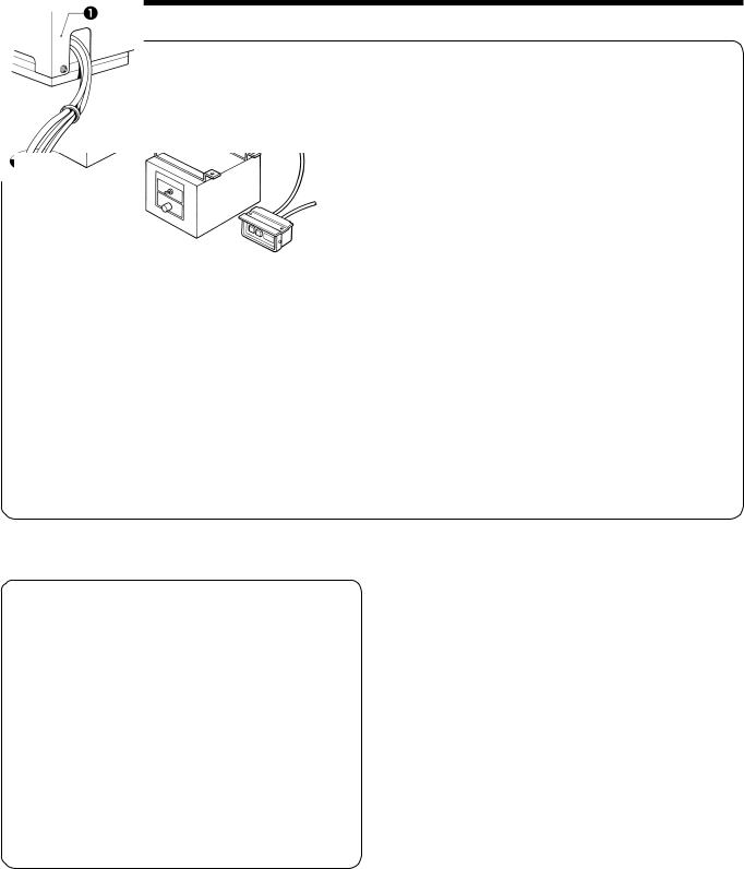
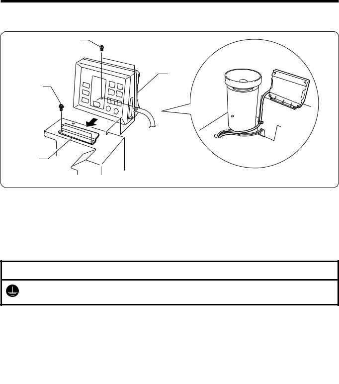
3-16. Installing the operation panel
The operation panel can be installed to either the top or bottom of the work table.
r
e
w
q
1.Install the operation panel presser plate q to the top of the button feeder cover with the two screws w.
2.Insert the panel e into the operation panel presser plate q, and then secure it with the two screws r.
3.Insert the connector cord t into the control box through the hole at the side of the box. Refer to “3-13. Connecting the cords” for details on connecting the cord.
3-17. Connecting the ground wire
 CAUTION
Be sure to connect the ground. If the ground connection is not secure, you run the risk of receiving a serious electric shock, and problems with correct operation may also occur.
Connect to the power switch. However, the black wire is insulated to the inside of the box and is not used.
Connect to ground
LK3-B448E MARKII/BA-16
17
Loading...