


 Loading...
Brother KE-434B, 435C, 431B, 434C, 432C User Manual
...KE-430B, 430C, 431B, 431C |
SERVICE MANUAL |
KE-432B, 432C, 433B |
|
KE-434B, 434C, 435B, 435C |
|
KE-436B, 436C, 484C |
|
BE-438B, 438C |
|
Please read this manual before using the machine.
Please keep this manual within easy reach for quick reference.
ELECTRONIC LOCKSTITCH BAR TACKER ELECTRONIC LOCKSTITCH BELT LOOP BAR TACKER ELECTRONIC LOCKSTITCH PATTERN TACKER ELECTRONIC LOCKSTITCH BUTTON SEWER

This service manual is intended for KE-430B series, KE-430C series, BE-438B, BE-438C, KE-484C; be sure to read the KE-430B series, KE-430C series, BE-438B, BE-438C, KE-484C instruction manual before this manual.
Carefully read the “SAFETY INSTRUCTIONS” below and the whole of this manual to understand this product before you start maintenance.
As a result of research and improvements regarding this product, some details of this manual may not be the same as those for the product you purchased.
If you have any questions regarding this product, please contact a Brother dealer.
SAFETY INSTRUCTIONS
1. Safety indications and their meanings
This service manual and the indications and symbols that are used on the machine itself are provided in order to ensure safe operation of this machine and to prevent accidents and injury to yourself or other people.
The meanings of these indications and symbols are given below.
Indications
DANGER The instructions which follow this term indicate situations where failure to follow the instructions will almost certainly result in death or severe injury.
The instructions which follow this term indicate situations where failure to follow the CAUTION instructions could cause injury when using the machine or physical damage to equipment
and surroundings.
Symbols


This symbol (  ) indicates something that you should be careful of. The picture inside the triangle indicates the nature of the caution that must be taken.
(For example, the symbol at left means “beware of injury”.)
This symbol (  ) indicates something that you must not do.
This symbol ( ) indicates something that you must do. The picture inside the circle indicates the nature of the thing that must be done.
(For example, the symbol at left means “you must make the ground connection”.)
i |
KE-430B, 430C series |

2. Notes on safety
 DANGER
Wait at least 5 minutes after turning off the power switch and disconnecting the power cord from the wall outlet before opening the face plate of the control box. Touching areas where high voltages are present can result in severe injury.
 CAUTION
Environmental requirements
Use the sewing machine in an area which is free from sources of strong electrical noise such as high-frequency welders.
Sources of strong electrical noise may cause problems with correct operation.
Any fluctuations in the power supply voltage should be within 10% of the rated voltage for the machine. Voltage fluctuations which are greater than this may cause problems with correct operation.
The power supply capacity should be greater than the requirements for the sewing machine’s electrical consumption.
Insufficient power supply capacity may cause problems with correct operation.
The pneumatic delivery capability should be greater than the requirements for the sewing machine’s total air consumption.
Insufficient pneumatic delivery capability may cause problems with correct operation.
The ambient temperature should be within the range of 5 C to 35 C during use.
Temperatures which are lower or higher than this may cause problems with correct operation.
The relative humidity should be within the range of 45% to 85% during use, and no dew formation should occur in any devices.
Excessively dry or humid environments and dew formation may cause problems with correct operation.
Avoid exposure to direct sunlight during use. Exposure to direct sunlight may cause problems with correct operation.
In the event of an electrical storm, turn off the power and disconnect the power cord from the wall outlet. Lightning may cause problems with correct operation.
Installation
Machine installation should only be carried out by a qualified technician.
Contact your Brother dealer or a qualified electrician for any electrical work that may need to be done.
The sewing machine weighs more than 52 kg. The installation should be carried out by two or more people.
Do not connect the power cord until installation is complete, otherwise the machine may operate if the foot switch is depressed by mistake, which could result in injury.
Hold the machine head with both hands when tilting it back or returning it to its original position. Furthermore, after tilting back the machine head, do not push the face plate side or the pulley side from above, as this could cause the machine head to topple over, which may result in personal injury or damage to the machine.
Be sure to connect the ground. If the ground connection is not secure, you run a high risk of receiving a serious electric shock, and problems with correct operation may also occur.
All cords should be secured at least 25 mm away from any moving parts. Furthermore, do not excessively bend the cords or secure them too firmly with staples, otherwise there is the danger that fire or electric shocks could occur.
 Install the belt covers to the machine head and motor.
If using a work table which has casters, the casters should be secured in such a way so that they cannot move.
Be sure to wear protective goggles and gloves when handling the lubricating oil and grease, so that they do not get into your eyes or onto your skin, otherwise inflammation can result.
Furthermore, do not drink the oil or eat the grease under any circumstances, as they can cause vomiting and diarrhoea.
Keep the oil out of the reach of children.
KE-430B, 430C series |
ii |
 CAUTION
Sewing
This sewing machine should only be used by opera- |
If using a work table which has casters, the casters |
tors who have received the necessary training in safe |
should be secured in such a way so that they cannot |
use beforehand. |
move. |
The sewing machine should not be used for any |
Attach all safety devices before using the sewing |
applications other than sewing. |
machine. If the machine is used without these |
Be sure to wear protective goggles when using the |
devices attached, injury may result. |
|
|
machine. |
Do not touch any of the moving parts or press any |
If goggles are not worn, there is the danger that if a |
objects against the machine while sewing, as this |
needle breaks, parts of the broken needle may enter |
may result in personal injury or damage to the |
your eyes and injury may result. |
machine. |
Set the needle to the needle up stop position before |
If an error occurs in machine operation, or if abnormal |
turning off the power. |
noises or smells are noticed, immediately turn off the |
If this is not done, the wiper may strike the needle, |
power switch. Then contact your nearest Brother |
which might cause the needle to break. |
dealer or a qualified technician. |
Turn off the power switch at the following times, |
If the machine develops a problem, contact your |
otherwise the machine may operate if the foot switch |
nearest Brother dealer or a qualified technician. |
is depressed by mistake, which could result in injury. |
|
When threading the needle |
|
When replacing the needle and bobbin |
|
When not using the machine and when leaving the |
|
machine unattended |
|
Cleaning
Set the needle to the needle up stop position before |
Be sure to wear protective goggles and gloves when |
||||
turning off the power. |
|
|
handling the lubricating oil and grease, so that they |
||
If this is not done, the wiper may strike the needle, |
do not get into your eyes or onto your skin, otherwise |
||||
which might cause the needle to break. |
|
inflammation can result. |
|||
Turn off the |
power switch |
before |
carrying out |
Furthermore, do not drink the oil or eat the grease un- |
|
der any circumstances, as they can cause vomiting |
|||||
cleaning, otherwise the machine may operate if the |
|||||
and diarrhoea. |
|||||
foot switch is |
depressed by |
mistake, |
which could |
||
Keep the oil out of the reach of children. |
|||||
result in injury. |
|
|
|
||
|
|
|
|
||
Maintenance and inspection
|
Maintenance and inspection of the sewing machine |
If the power switch and air need to be left on when |
|
should only be carried out by a qualified technician. |
carrying out some adjustment, be extremely careful to |
|
Ask your Brother dealer or a qualified electrician to |
observe all safety precautions. |
|
|
|
|
carry out any maintenance and inspection of the |
Hold the machine head with both hands when tilting it |
|
electrical system. |
back or returning it to its original position. |
|
Set the needle to the needle up stop position before |
Furthermore, after tilting back the machine head, do |
|
turning off the power. |
not push the face plate side or the pulley side from |
|
If this is not done, the wiper may strike the needle, |
above, as this could cause the machine head to |
|
which might cause the needle to break. |
topple over, which may result in personal injury or |
|
Turn off the power switch and disconnect the power |
damage to the machine. |
|
Use only the proper replacement parts as specified |
|
|
cord from the wall outlet at the following times, |
|
|
otherwise the machine may operate if the foot switch |
by Brother. |
|
is depressed by mistake, which could result in injury. |
If any safety devices have been removed, be abso- |
|
When carrying out inspection, adjustment and main- |
lutely sure to re-install them to their original positions |
|
tenance |
and check that they operate correctly before using |
|
When replacing consumable parts such as the ro- |
the machine. |
|
tary hook |
Any problems in machine operation which result from |
|
Disconnect the air hoses from the air supply and wait |
unauthorized modifications to the machine will not be |
|
for the needle on the pressure gauge to drop to “0” |
covered by the warranty. |
|
before carrying out inspection, adjustment and repair |
|
|
of any parts which use the pneumatic equipment. |
|
|
|
|
iii |
KE-430B, 430C series |
|
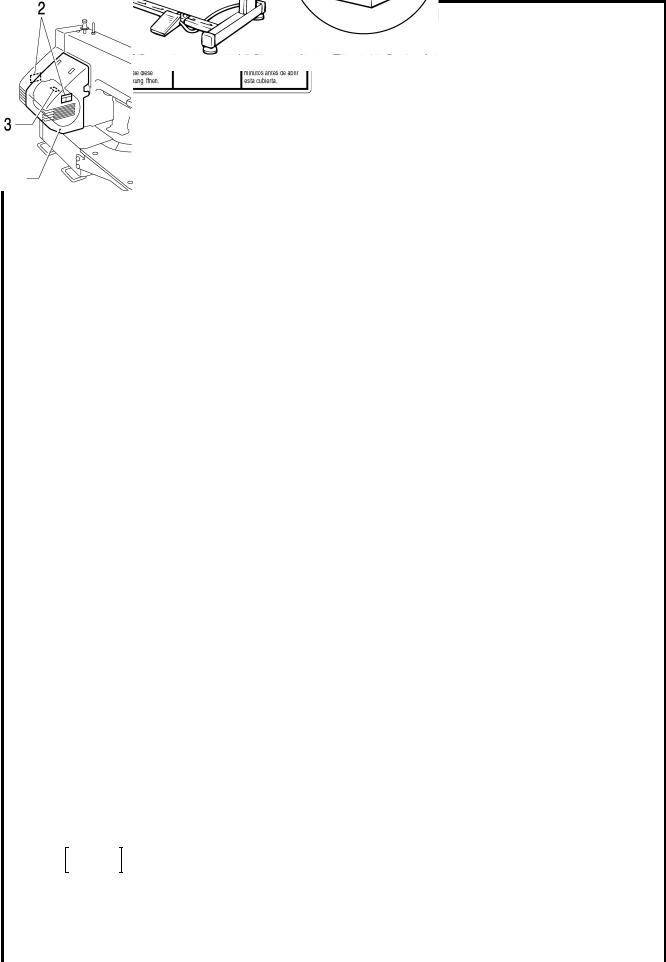
3. Warning labels
The following warning labels appear on the sewing machine.
Please follow the instructions on the labels at all times when using the machine. If the labels have been removed or are difficult to read, please contact your nearest Brother dealer.
1 |
2 |
Safety devices
Eye guard
Finger guard
3  High temperature warning display Thread take-up cover
Thread take-up solenoid cover Belt cover
Frame side cover, etc.
4 
5
Be sure to connect the ground. If the ground connection is not secure, you run a high risk of receiving a serious electric shock, and problems with correct operation may also occur.
Direction of operation
Thread take-up cover
Frame side cover
2670Q
Eye guard
|
|
|
|
Thread take-up |
Belt cover |
||
solenoid cover |
|||
|
|||
|
|
||
|
Finger guard |
|
|
|
|
|
|
|
|
|
|
KE-430B
KE-430C
|
2737Q |
|
|
KE-430B, 430C series |
iv |
CONTENTS
1. SPECIFICATIONS ............................... |
1 |
|
1-1. |
SPECIFICATIONS ........................................... |
1 |
1-2. |
Standard thread tension................................... |
5 |
2. MECHANICAL DESCRIPTIONS ......... |
7 |
|
2-1. |
Needle bar and thread take-up |
|
|
mechanisms..................................................... |
7 |
2-2. |
Lower shaft and shuttle race mechanisms ....... |
9 |
2-3. |
Work clamp lifter mechanism ........................... |
10 |
2-4. |
Work clamp open-close mechanism |
|
|
(KE-432B, 432C).............................................. |
12 |
2-5. |
Thread wiper mechanism................................. |
13 |
2-6. |
Feed mechanism ............................................. |
15 |
2-7. |
Thread trimmer mechanism ............................. |
17 |
2-8. |
Thread nipper mechanism ............................... |
19 |
2-9. |
Thread take-up mechanism ............................. |
21 |
3. DISASSEMBLY ................................... |
22 |
|
3-1. |
Covers.............................................................. |
22 |
3-2. |
Work clamp arm mechanism |
|
|
(KE-430B, 430C, 431B, 431C)......................... |
24 |
3-3. |
Work clamp arm mechanism |
|
|
(KE-432B, 432C).............................................. |
25 |
3-4. |
Work clamp arm mechanism (KE-433B) .......... |
26 |
3-5. |
Work clamp arm mechanism (KE-434B, 434C, |
|
|
435B, 435C, 436B, 436C, 484C)........................... |
27 |
3-6. |
Work clamp arm (BE-438B, 438C) ..................... |
29 |
3-7. |
Shuttle hook mechanism.................................. |
30 |
3-8. |
Needle bar mechanism .................................... |
31 |
3-9. |
Stepping foot mechanism |
|
|
(KE-435B, 435C, 436B, 436C)......................... |
32 |
3-10. Upper shaft mechanism.................................... |
33 |
|
3-11. Lower shaft mechanism.................................... |
35 |
|
3-12. Feed mechanism (1)......................................... |
37 |
|
3-13. Feed mechanism (2)......................................... |
39 |
|
3-14. |
Work clamp lifter mechanism |
|
|
(Solenoid specifications) .................................. |
41 |
3-15. Stepping foot lifter mechanism |
|
|
|
(KE-435B, 435C, 436B, 436C)......................... |
43 |
3-16. |
Thread wiper mechanism.................................. |
44 |
3-17. |
Thread nipper mechanism ................................ |
47 |
3-18. |
Thread take-up mechanism .............................. |
49 |
3-19. |
Thread trimmer mechanism .............................. |
51 |
4. ASSEMBLY......................................... |
54 |
|
4-1. |
Thread trimmer mechanism (1) ........................ |
54 |
4-2. |
Thread nipper mechanism................................ |
56 |
4-3. |
Thread wiper mechanism ................................. |
59 |
4-4. |
Thread take-up mechanism.............................. |
62 |
4-5. |
Work clamp lifter mechanism |
|
|
(Solenoid specifications)................................... |
65 |
4-6. |
Feed mechanism (1)......................................... |
70 |
4-7. |
Feed mechanism (2)......................................... |
74 |
4-8. |
Upper shaft mechanism.................................... |
76 |
4-9. |
Stepping foot lifter mechanism |
|
|
(KE-435B, 435C, 436B, 436C) ......................... |
79 |
4-10. |
Stepping foot mechanism |
|
|
(KE-435B, 435C, 436B, 436C) ......................... |
80 |
4-11. |
Needle bar mechanism..................................... |
82 |
4-12. |
Lower shaft mechanism.................................... |
83 |
4-13. |
Thread trimmer mechanism (2) ........................ |
86 |
4-14. |
Shuttle hook mechanism .................................. |
87 |
4-15. |
Work clamp arm mechanism |
|
|
(KE-430B, 430C, 431B, 431C) ......................... |
89 |
4-16. |
Work clamp arm mechanism |
|
|
(KE-432B, 432C) .............................................. |
90 |
4-17. Work clamp arm mechanism (KE-433B)........... |
91 |
|
4-18. Work clamp arm mechanism (KE-434B, 434C, |
|
|
|
435B, 435C, 436B, 436C, 484C) ........................... |
92 |
4-19. Work clamp arm mechanism |
|
|
|
(BE-438B, 438C) .............................................. |
94 |
4-20. |
Work clamp arm mechanism |
|
|
(Applying grease) ............................................. |
95 |
4-21. |
Covers .............................................................. |
97 |
KE-430B, 430C series
5. ADJUSTMENT..................................... |
99 |
|
5-1. |
Adjusting the needle bar height........................ |
99 |
5-2. |
Adjusting the needle bar lift amount................. |
100 |
5-3. |
Adjusting the driver needle guard .................... |
101 |
5-4. |
Adjusting the needle clearance ........................ |
101 |
5-5. |
Adjusting the shuttle race thread guide ............ |
102 |
5-6. |
Adjusting the clearance between the shuttle |
|
|
hook and bobbin case holder position bracket |
|
|
(KE-484C) ........................................................ |
103 |
5-7. |
Adjusting the work clamp lift amount |
|
|
(KE-430B, 430C, 431B, 431C, 433B) .............. |
104 |
5-8. |
Adjusting the work clamp lift amount |
|
|
(KE-432B, 432C).............................................. |
104 |
5-9. |
Adjusting the work clamp lift amount (KE-434B, |
|
|
434C, 435B, 435C, 436B, 436C, 484C) ........... |
105 |
5-10. |
Adjusting the button clamp lift amount |
|
|
(BE-438B, 438C).............................................. |
106 |
5-11. |
Work clamp pressure adjustment |
|
|
(KE-432B, 432C).............................................. |
107 |
5-12. Adjusting the holding pressure |
|
|
|
(BE-438B, 438C).............................................. |
107 |
5-13. Work clamp closing-distance adjustment |
|
|
|
(KE-432B, 432C).............................................. |
108 |
5-14. Adjusting the position of the button holder |
|
|
|
(BE-438B, 438C).............................................. |
109 |
5-15. Work clamp adjustment |
|
|
|
(KE-435B, 435C, 436B, 436C)......................... |
109 |
5-16. Changing the work clamp lift |
|
|
|
(KE-435B, 435C, 436B, 436C)......................... |
110 |
5-17. Adjusting the thread wiper ................................ |
111 |
|
5-18. Adjusting the thread take-up amount................ |
114 |
|
5-19. Adjusting the movable knife.............................. |
116 |
|
5-20. Adjusting the position of the thread trimming |
|
|
|
link mechanism ................................................ |
122 |
5-21. Adjusting the backlash...................................... |
123 |
|
5-22. Adjusting the presser solenoid position |
|
|
|
(Solenoid specifications) .................................. |
124 |
5-23. Adjusting the sensor perceive plate position |
|
|
|
(Solenoid specifications) .................................. |
125 |
5-24. Adjusting the home position.............................. |
126 |
5-25. Adjusting the needle up stop position ............... |
129 |
5-26. Adjusting the tension of the upper shaft timing |
|
belt ................................................................... |
129 |
5-27. Checking the head position switch.................... |
130 |
5-28. Work clamp interchangeability |
|
(KE-433B)....................................................... |
131 |
5-29. Work clamp interchangeability (KE-434B, |
|
434C, 435B, 435C, 436B, 436C, 484C) ........... |
131 |
5-30. Adjustment of air pressure (Pneumatic |
|
specifications)................................................... |
132 |
5-31. Adjustment of inner clamping device ................ |
132 |
6. TROUBLESHOOTING ........................ |
133 |
7. OPTIONAL PARTS ............................. |
136 |
8. ELECTRIC MECHANISM.................... |
138 |
8-1. Precautions at the time of adjustment................. |
138 |
8-2. Components inside the control box and |
|
the operation panel........................................... |
138 |
8-3. Fuse explanation ................................................ |
139 |
8-4. Connectors ......................................................... |
140 |
8-5. Explanation of the DIP switches ......................... |
147 |
8-6. Explanation of the memory switches |
|
(KE-430*, 431*, 432*, 433B, 434*, 435*, |
|
484C, BE-438*) ................................................ |
150 |
8-7. Explanation of the memory switches |
|
(KE-436B, 436C) .............................................. |
155 |
8-8. Setting the work clamp mode.............................. |
159 |
8-9. Checking the input sensor and DIP switch |
|
input.................................................................. |
161 |
8-10. Checking the input voltage................................ |
163 |
8-11. Clearing all memory settings............................. |
164 |
8-12. Confirming software version ............................. |
165 |
8-13. Table of error codes.......................................... |
167 |
8-14. Troubleshooting ................................................ |
171 |
8-15. Control circuit block diagram............................. |
190 |
KE-430B, 430C series
1. SPECIFICATIONS
. SPECIFICATIONS
- . SPECIFICATIONS
|
1 |
Ordinary materials |
|
2 |
|
Bar tacking length |
|
|
|
1 |
|
|
Ordinary materials |
||
|
5 |
|
|
6 -14 mm |
|
|
|
|
2 |
|
|
Denim |
|||
|
|
|
|
|
|
|
|
|
|
|
|||||
|
2 |
Denim |
|
3 |
|
Bar tacking length |
|
|
|
7 |
|
|
Knitted materials |
||
|
7 |
Knitted materials |
|
|
14 - 25 mm |
|
|
|
|
|
|
|
|||
|
|
|
|
|
|
|
|
|
|
|
|||||
|
|
|
|
|
|
|
|
|
|
|
KE-432B |
|
|
|
|
|
|
|
|
|
KE-430B |
|
KE-431B |
|
|
|
KE-433B |
||||
|
|
|
|
|
|
|
Electronic lockstitch |
|
|
Electronic lockstitch |
|||||
|
|
|
Electronic lockstitch |
|
Electronic lockstitch |
|
|
|
|||||||
|
|
|
|
|
eyelet buttonhole |
|
|
decorative pattern |
|||||||
|
|
|
|
|
bar tacker |
|
belt loop bar tacker |
|
|
|
|||||
|
|
|
|
|
|
|
end bar tacker |
|
|
tacker |
|||||
|
|
|
|
|
|
|
|
|
|
|
|
|
|||
Stitch formation |
|
|
|
|
|
|
Single needle lock stitch |
|
|||||||
|
|
|
|
|
|
|
|
|
|
|
|
|
|||
Maximum sewing speed |
|
|
|
|
|
2,700 rpm |
|
|
|
|
|
2,500 rpm |
|||
|
|
|
|
|
|
|
|
|
|||||||
Maximum pattern size |
|
|
|
30 10 mm max. |
|
12 3 mm max. |
|
30 30 mm max. |
|||||||
|
|
|
|
|
|
|
|||||||||
Feed mechanism |
|
|
|
R- intermittent feed mechanism (pulse-motor driven mechanism) |
|||||||||||
|
|
|
|
|
|
|
|
|
|||||||
Stitch length |
|
|
|
|
|
|
0.1 - 10.0 mm |
|
|||||||
|
|
|
|
|
|
|
|
|
|||||||
Number of stitches |
|
|
|
|
|
|
Variable |
|
|||||||
|
|
|
|
|
|||||||||||
Maximum stitch number |
|
|
|
20,000 stitches (including 10,000 stitches which can be added) |
|||||||||||
|
|
|
|
|
|
|
|
|
|||||||
Work clamp lifter |
|
|
|
|
|
|
Solenoid type |
|
|||||||
|
|
|
|
|
|
|
|
|
|||||||
Work clamp height |
|
|
|
|
|
|
17 mm max. |
|
|||||||
|
|
|
|
|
|
|
|
||||||||
Rotary hook |
|
|
|
|
|
Shuttle hook (shuttle hook 2, optional) |
|
||||||||
|
|
|
|
|
|
|
|
|
|||||||
Wiper device |
|
|
|
|
|
|
Standard equipment |
|
|||||||
|
|
|
|
|
|
|
|
|
|||||||
Thread trimmer device |
|
|
|
|
|
|
Standard equipment |
|
|||||||
|
|
|
|
|
|
|
|
|
|||||||
Thread take-up device |
|
|
|
|
|
|
Standard equipment |
|
|||||||
|
|
|
|
|
|||||||||||
Data storage method |
|
|
|
P-ROM (Any sewing pattern can be added using PS-3000.) |
|||||||||||
|
|
|
|
|
|
|
|
|
|
|
|
|
|||
Number of user programs |
|
|
|
|
|
|
|
16 |
|
|
|
|
|||
|
|
|
|
|
|
|
|
|
|
|
|
|
|||
Number of cycle programs |
|
|
|
|
|
|
|
4 |
|
|
|
|
|||
|
|
|
|
|
|
3 sewing patterns are |
|
|
|||||||
|
|
|
35 sewing patterns are |
|
6 sewing patterns are |
|
|
|
|
||||||
Number of stored data |
|
|
set already |
|
set already |
|
set already |
|
|
|
|||||
|
|
|
(Up to 100 patterns can be added. Total number of stitches of stored data |
||||||||||||
|
|
|
|
|
|
||||||||||
|
|
|
|
|
|
|
|
which can be added is within 10,000.) |
|
||||||
Motor |
|
|
|
|
|
|
Three-phase 400W induction motor |
|
|||||||
|
|
|
|
|
|
|
Machine head: 52 kg, Operation panel: 0.6 kg, |
|
|||||||
Weights |
|
|
|
|
|
||||||||||
|
|
|
Control box: 9 - 19 kg (depending on destination) |
|
|||||||||||
|
|
|
|
|
|
|
|||||||||
Power source |
|
|
|
|
|
Single-phase 110, 220 - 230, 240V |
|
||||||||
|
|
|
|
|
|
3-phase 220-230, 380, 400V |
|
||||||||
|
|
|
|
|
|
|
Maximum electric power consumption; 600VA |
|
|||||||
1 |
KE-430B, 430C series |
1. SPECIFICATIONS
|
1 |
|
Medium materials |
|
|
|
|
|
|
|
|
|
|
2 |
|
Heavy materials |
|
|
|
|
|
|
|
|
|
|
|
|
|
|
|
|
|
KE-436B |
|
|
|
|
|
|
|
|
|
|
|
|
|
|
|
|
|
|
|
|
|
KE-434B |
|
KE-435B |
|
Electronic lockstitch |
|
|
BE-438B |
|
|
|
|
|
|
Electronic lockstitch |
|
pattern tacker |
|
|
|||
|
|
|
|
Electronic lockstitch |
|
|
|
|
Electronic lockstitch |
|||
|
|
|
|
|
pattern tacker |
|
with stepping foot |
|
|
|||
|
|
|
|
pattern tacker |
|
|
|
|
button sewer |
|||
|
|
|
|
|
with stepping foot |
|
and programming |
|
|
|||
|
|
|
|
|
|
|
|
|
|
|
||
|
|
|
|
|
|
|
|
function |
|
|
|
|
Stitch formation |
|
|
Single needle lock stitch |
|
|
|||||||
|
|
|
|
|
|
|
|
|
|
|||
Maximum sewing speed |
|
|
2,500 rpm (Pitch 3 mm) |
|
|
|
2,500 rpm |
|||||
|
|
|
|
|
|
|
|
|
|
|||
Maximum pattern size |
|
|
100 60 mm max. |
|
|
|
0 - 6.4 0 - 6.4 mm |
|
||||
|
|
|
|
|
|
|
||||||
Feed mechanism |
R- intermittent feed mechanism (pulse-motor driven mechanism) |
|||||||||||
|
|
|
|
|
|
|
|
|||||
Stitch length |
|
|
0.1 - 10.0 mm |
|
|
|||||||
|
|
|
|
|
|
|
|
|||||
Number of stitches |
|
|
Variable |
|
|
|||||||
|
|
|
|
|
|
|
|
|
|
|
|
|
|
|
|
|
20,000 stitches (including 10,000 stitches |
|
20,000 stitches |
|
20,000 stitches |
||||
Maximum stitch number |
|
|
(including 10,000 |
|||||||||
which can be added) |
|
(One pattern) |
|
stitches which can |
||||||||
|
|
|
|
|
|
|||||||
|
|
|
|
|
|
|
|
|
|
|
be added) |
|
Work clamp lifter |
Solenoid type or |
|
Pneumatic type |
|
Solenoid type |
|||||||
pneumatic type |
|
|
||||||||||
|
|
|
|
|
|
|
|
|
|
|
|
|
Work clamp height |
|
17 mm max. (for solenoid) |
|
|
|
13 mm max. |
||||||
25 mm max. (for pneumatic) (Max. 17 mm for inner clamping device) |
|
|||||||||||
|
|
|
|
|
|
|
||||||
Rotary hook |
|
|
Shuttle hook (shuttle hook 2, optional) |
|
|
|||||||
Wiper device |
|
|
Standard equipment |
|
|
|||||||
|
|
|
|
|
|
|
||||||
Thread trimmer device |
|
|
Standard equipment |
|
|
|||||||
|
|
|
|
|
|
|
||||||
Thread take-up device |
|
|
Standard equipment |
|
|
|||||||
|
|
|
|
|
|
|
||||||
Stepping foot lift amount |
|
|
18 mm |
|
|
|
||||||
Stepping foot stroke |
|
|
0 mm, 3 - 8 mm |
|
|
|
||||||
Safety device |
|
|
built-in stopping mechanism |
|
|
|||||||
|
|
|
|
|
|
|
|
|
|
|
P-ROM (Any sewing |
|
Data storage method |
P-ROM (Any sewing pattern can be added |
|
3.5 floppy disk |
|
pattern can be |
|||||||
using PS-3000.) |
|
2HD/1.44MB, 2DD |
|
added using |
||||||||
|
|
|
|
|
|
|||||||
|
|
|
|
|
|
|
|
|
|
|
PS-3000.) |
|
Number of user programs |
|
16 |
|
|
|
|
16 |
|
||||
|
|
|
|
|
|
|
|
|
||||
Number of cycle programs |
|
4 |
|
|
|
|
4 |
|
||||
|
|
|
|
|
|
|
|
|
|
|
|
|
|
|
|
|
|
|
|
|
|
|
|
49 sewing patterns are |
|
Number of stored data |
|
(*) |
|
|
|
|
set already |
|||||
|
|
|
|
|
|
|
||||||
|
|
|
|
|
(*) |
|
||||||
|
|
|
|
|
|
|
|
|
|
|
|
|
|
|
|
|
|
|
|
|
|
||||
Motor |
|
|
|
Three-phase 400W induction motor |
|
|
||||||
|
|
|
|
Machine head: 56 kg, Operation panel: 0.6 kg (2.8 kg: KE-436B), |
||||||||
Weights |
|
|||||||||||
|
|
Control box: 9 - 19 kg (depending on destination) |
|
|
||||||||
|
|
|
|
|
|
|
||||||
Power source |
|
|
Single-phase 110, 220 - 230, 240V |
|
|
|||||||
|
|
3-phase 220-230, 380, 400V |
|
|
||||||||
|
|
|
|
|
|
Maximum electric power consumption; 600VA |
|
|
||||
* Up to 100 patterns can be added. Total number of stitches of stored data which can be added is within 10,000.
KE-430B, 430C series |
2 |

1. SPECIFICATIONS
|
1 |
Ordinary materials |
|
2 |
|
Bar tacking length |
|
|
|
|
|
|
||
|
2 |
Denim |
|
|
6 -14 mm |
|
|
|
|
|
|
|||
|
|
|
|
|
|
|
|
|
|
|||||
|
7 |
Knitted materials |
|
3 |
|
Bar tacking length |
|
|
|
|
|
|
||
|
|
|
|
|
14 -25 mm |
|
|
|
|
|
|
|||
|
|
|
|
|
|
|
|
|
|
|
|
|||
|
|
|
|
|
|
|
|
|
|
|
KE-432C |
|
|
|
|
|
|
|
|
KE-430C |
|
KE-431C |
|
|
|
BE-438C |
|||
|
|
|
|
|
|
|
Electronic lockstitch |
|
|
|||||
|
|
|
Electronic lockstitch |
|
Electronic lockstitch |
|
|
|
Electronic lockstitch |
|||||
|
|
|
|
|
eyelet buttonhole |
|
|
|||||||
|
|
|
|
|
bar tacker |
|
belt loop bar tacker |
|
|
|
button sewer |
|||
|
|
|
|
|
|
|
end bar tacker |
|
|
|||||
|
|
|
|
|
|
|
|
|
|
|
|
|
|
|
Stitch formation |
|
|
|
|
|
|
Single needle lock stitch |
|
||||||
|
|
|
|
|
|
|
|
|
|
|
|
|||
Maximum sewing speed |
|
|
|
|
|
2,700 rpm |
|
|
|
|
2,500 rpm |
|||
|
|
|
|
|
|
|
|
|
||||||
Maximum pattern size |
|
30 26 mm max. |
|
30 10 mm max. |
|
12 3 mm max. |
|
0 - 6.4 0 - 6.4 mm |
||||||
|
|
|
|
|
|
|
|
|||||||
Feed mechanism |
|
|
|
R- intermittent feed mechanism (pulse-motor driven mechanism) |
||||||||||
|
|
|
|
|
|
|
|
|
||||||
Stitch length |
|
|
|
|
|
|
0.1 - 10.0 mm |
|
||||||
|
|
|
|
|
|
|
|
|
||||||
Number of stitches |
|
|
|
|
|
|
Variable |
|
||||||
|
|
|
|
|
||||||||||
Maximum stitch number |
|
|
|
20,000 stitches (including 10,000 stitches which can be added) |
||||||||||
|
|
|
|
|
|
|
|
|
||||||
Work clamp lifter |
|
|
|
|
|
|
Solenoid type |
|
||||||
|
|
|
|
|
|
|
|
|
|
|
|
|||
Work clamp height |
|
|
|
|
|
17 mm max. |
|
|
|
|
13 mm max. |
|||
|
|
|
|
|
|
|
|
|
|
|||||
Rotary hook |
|
|
|
|
|
Shuttle hook (shuttle hook 2, optional) |
|
|||||||
|
|
|
|
|
|
|
|
|
||||||
Wiper device |
|
|
|
|
|
|
Standard equipment |
|
||||||
|
|
|
|
|
|
|
|
|
||||||
Thread trimmer device |
|
|
|
|
|
|
Standard equipment |
|
||||||
|
|
|
|
|
|
|
|
|
||||||
Thread take-up device |
|
|
|
|
|
|
Standard equipment |
|
||||||
|
|
|
|
|
||||||||||
Data storage method |
|
|
|
P-ROM (Any sewing pattern can be added using PS-3000.) |
||||||||||
|
|
|
|
|
|
|
|
|
|
|
|
|||
Number of user programs |
|
|
|
|
|
|
|
16 |
|
|
|
|||
|
|
|
|
|
|
|
|
|
|
|
|
|||
Number of cycle programs |
|
|
|
|
|
|
|
4 |
|
|
|
|||
|
|
|
|
|
|
|
3 sewing patterns are |
|
|
|||||
|
|
|
61 sewing patterns are |
|
6 sewing patterns are |
|
|
|
49 sewing patterns are |
|||||
Number of stored data |
|
|
set already |
|
set already |
|
set already |
|
|
set already |
||||
|
|
|
(Up to 100 patterns can be added. Total number of stitches of stored data |
|||||||||||
|
|
|
|
|
|
|||||||||
|
|
|
|
|
|
|
|
which can be added is within 10,000.) |
|
|||||
Motor |
|
|
|
|
|
|
Three-phase 400W induction motor |
|
||||||
|
|
|
|
|
|
|
|
Machine head: 52 kg, Operation panel: 0.6 kg, |
|
|||||
Weights |
|
|
|
|
|
|
||||||||
|
|
|
|
Control box: 9 - 19 kg (depending on destination) |
|
|||||||||
|
|
|
|
|
|
|
|
|||||||
Power source |
|
|
|
|
|
Single-phase 110, 220 - 230, 240V |
|
|||||||
|
|
|
|
|
|
3-phase 220-230, 380, 400V |
|
|||||||
|
|
|
|
|
|
|
|
Maximum electric power consumption; 600VA |
|
|||||
3 |
KE-430B, 430C series |
1. SPECIFICATIONS
|
1 |
|
Medium materials |
|
|
|
|
|
|
|
|
2 |
|
Heavy materials |
|
|
|
|
|
|
|
|
|
|
|
|
|
|
KE-436C |
|
|
|
|
|
|
|
|
|
|
|
|
|
|
|
|
|
|
KE-434C |
|
KE-435C |
Electronic lockstitch |
|
|
KE-484C |
|
|
|
|
|
Electronic lockstitch |
pattern tacker |
|
|
Electronic lockstitch |
|
|
|
|
|
Electronic lockstitch |
|
|
|
|||
|
|
|
|
|
pattern tacker |
with stepping foot |
|
|
pattern tacker |
|
|
|
|
|
pattern tacker |
|
|
|
|||
|
|
|
|
|
with stepping foot |
and programming |
|
|
with treble hook |
|
|
|
|
|
|
|
|
|
|||
|
|
|
|
|
|
|
function |
|
|
|
Stitch formation |
|
|
Single needle lock stitch |
|
||||||
|
|
|
|
|
|
|
|
|
|
|
Maximum sewing speed |
|
|
2,500 rpm (Pitch 3 mm) |
|
|
|
2,200 rpm |
|||
|
|
|
|
|
(Pitch 3 mm) |
|||||
|
|
|
|
|
|
|
|
|
|
|
Maximum pattern size |
|
|
100 60 mm max. |
|
||||||
|
R- intermittent feed mechanism (pulse-motor driven mechanism) |
|||||||||
Feed mechanism |
||||||||||
|
|
|
|
|
|
|
||||
Stitch length |
|
|
0.1 - 10.0 mm |
|
||||||
|
|
|
|
|
|
|
||||
Number of stitches |
|
|
Variable |
|
||||||
|
|
|
|
|
|
|
|
|
|
|
|
|
|
|
|
|
|
|
|
|
20,000 stitches |
Maximum stitch number |
20,000 stitches (including 10,000 stitches |
20,000 stitches |
|
|
(including 10,000 |
|||||
which can be added) |
(One pattern) |
|
|
stitches which can |
||||||
|
|
|
|
|
|
|||||
|
|
|
|
|
|
|
|
|
|
be added) |
Work clamp lifter |
Solenoid type or |
|
|
Pneumatic type |
|
|||||
pneumatic type |
|
|
|
|||||||
|
|
|
|
|
|
|
|
|
|
|
Work clamp height |
17 |
mm max. (for solenoid), 25 mm max. (for pneumatic) |
||||||||
|
|
(Max. 17 mm for inner clamping device) |
|
|||||||
|
|
|
|
|
|
|
||||
Rotary hook |
Shuttle hook (shuttle hook 2, optional) |
|
|
Treble hook |
||||||
Wiper device |
|
|
Standard equipment |
|
||||||
|
|
|
|
|
|
|
||||
Thread trimmer device |
|
|
Standard equipment |
|
||||||
|
|
|
|
|
|
|
||||
Thread take-up device |
|
|
Standard equipment |
|
||||||
|
|
|
|
|
|
|
||||
Stepping foot lift amount |
|
|
18 mm |
|
|
|||||
Stepping foot stroke |
|
|
0 mm, 3 - 8 mm |
|
|
|||||
Safety device |
|
|
built-in stopping mechanism |
|
||||||
|
|
|
|
P-ROM (Any sewing pattern can be added |
3.5 floppy disk |
|
P-ROM (Any sewing |
|||
Data storage method |
|
pattern can be |
||||||||
using PS-3000.) |
2HD/1.44MB, 2DD |
|
added using |
|||||||
|
|
|
|
|
||||||
|
|
|
|
|
|
|
|
|
|
PS-3000.) |
Number of user programs |
|
16 |
|
|
|
16 |
||||
|
|
|
|
|
|
|
||||
Number of cycle programs |
|
4 |
|
|
|
4 |
||||
|
|
|
|
|
|
|
||||
Number of stored data |
|
(*) |
|
|
|
(*) |
||||
|
|
|
|
|
|
|
|
|||
Motor |
|
|
|
Three-phase 400W induction motor |
|
|||||
|
|
|
|
Machine head: 56 kg, Operation panel: 0.6 kg (2.8 kg: KE-436C), |
||||||
Weights |
|
|||||||||
|
|
Control box: 9 - 19 kg (depending on destination) |
|
|||||||
|
|
|
|
|
|
|||||
|
|
|
|
|
|
Single-phase 110, 220 - 230, 240V |
|
|||
Power source |
|
|
3-phase 220-230, 380, 400V |
|
||||||
|
|
|
|
|
|
Maximum electric power consumption; 600VA |
|
|||
* Up to 100 patterns can be added. Total number of stitches of stored data which can be added is within 10,000.
KE-430B, 430C series |
4 |

1. SPECIFICATIONS
- . Standard thread tension
[KE-430B, 430C, 431B, 431C, 432B, 432C, 433B, 434B, 434C, 435B, 435C, 436B, 436C]
|
Medium materials |
|
Heavy materials (Denim) |
Knitted materials |
|||||||
Use |
(Ordinary materials) |
|
|||||||||
|
|
|
|
|
|
|
|||||
Standard hook |
|
Large hook |
|
Standard hook |
Large hook |
Standard hook |
|||||
|
|
|
|||||||||
|
|
|
|
|
|
|
|
|
|
|
|
Upper thread |
#50 or |
|
← |
|
#30 or |
|
← |
#60 or equivalent |
|||
equivalent |
|
|
equivalent |
|
|||||||
|
|
|
|
|
|
|
|
|
|||
Lower thread |
#60 or |
|
← |
|
#50 or |
|
← |
#80 or equivalent |
|||
equivalent |
|
|
equivalent |
|
|||||||
|
|
|
|
|
|
|
|
|
|||
Upper thread tension |
0.8 - 1.2 |
|
1.0 - 1.3 |
|
1.2 - 1.6 |
|
|
1.4 - 1.8 |
|
0.8 - 1.2 |
|
(N) |
|
|
|
|
|
||||||
|
|
|
|
|
|
|
|
|
|
|
|
Lower thread tension |
0.2 - 0.3 |
|
← |
|
0.2 - 0.3 |
|
|
← |
0.25 - 0.3 |
||
(N) |
|
|
|
|
|||||||
|
|
|
|
|
|
|
|
|
|
|
|
Thread take-up |
|
|
|
|
|
|
|
|
|
|
|
spring height |
6 - 8 |
|
← |
|
6 - 8 |
|
|
← |
6 - 8 |
||
(mm) |
|
|
|
|
|
|
|
|
|
|
|
Thread take-up |
|
|
|
|
|
|
|
|
|
|
|
spring tension |
0.3 - 0.4 |
|
← |
|
0.5 - 0.6 |
|
|
← |
0.3 - 0.4 |
||
(N) |
|
|
|
|
|
|
|
|
|
|
|
Pre-tension (N) |
0.5 - 0.8 |
|
← |
|
0.3 - 0.5 |
|
|
← |
0.5 - 0.8 |
||
Needle |
DP×5 14 |
|
← |
|
DP×17NY 19 |
← |
DP×5 9 |
||||
[BE-438B, 438C, KE-484C] |
|
|
|
|
|
|
|
|
|
||
|
|
|
|
|
|
|
|
|
|
||
Model |
BE-438B |
|
|
|
BE-438C |
|
|
KE-484C |
|||
|
|
|
|
|
|
|
|
|
|||
Needle |
TQ×1 12 |
|
|
TQ×1 12 |
|
DP×17NY 12 |
|
DP×17 25 |
|||
Upper thread |
#60 or equivalent |
|
|
#60 or equivalent |
|
#4 or equivalent |
|||||
|
|
|
|
|
|
|
|||||
Lower thread |
#60 or equivalent |
|
|
#60 or equivalent |
|
#4 or equivalent |
|||||
|
|
|
|
|
|
|
|
|
|
|
|
Upper thread tension |
0.7 - 1.3 |
|
|
|
0.7 - 1.3 |
|
|
0.7 - 1.5 |
|
4.5 - 5.0 |
|
(N) |
|
|
|
|
|
|
|||||
|
|
|
|
|
|
|
|
|
|
|
|
Lower thread tension |
0.3 - 0.4 |
|
|
|
0.3 - 0.4 |
|
|
1.0 - 1.2 |
|||
(N) |
|
|
|
|
|
||||||
|
|
|
|
|
|
|
|
|
|
|
|
Thread take-up |
|
|
|
|
|
|
|
|
|
|
|
spring height |
6 - 8 |
|
|
|
6 - 8 |
|
|
|
0 - 5 |
||
(mm) |
|
|
|
|
|
|
|
|
|
|
|
Thread take-up |
|
|
|
|
|
|
|
|
|
|
|
spring tension |
0.4 - 0.6 |
|
|
|
0.4 - 0.6 |
|
|
2.0 - 2.5 |
|||
(N) |
|
|
|
|
|
|
|
|
|
|
|
Pre-tension (N) |
0.1 - 0.3 |
|
|
|
0.1 - 0.3 |
|
|
0.05 - 0.3 |
|
0.3 - 0.5 |
|
5 |
KE-430B, 430C series |
1. SPECIFICATIONS
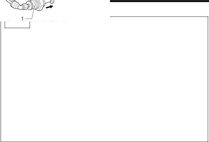
- - . Measuring tension
Upper thread tension |
Lower thread tension |
3564Q |
|
3565Q |
Thread take-up spring height |
|
Thread take-up spring tension |
|
|
1–2 mm |
|
Measure the value when the thread take-up |
|
3566Q |
spring starts to extend. |
3567Q |
*When the spring height (stroke) is great or the spring tension is insufficient, it may cause the thread end length to vary after thread trimming.
KE-430B, 430C series |
6 |

2. MECHANICAL DESCRIPTIONS
. MECHANICAL DESCRIPTIONS
The mechanisms operate in the order of the numbers given in the illustrations.
- . Needle bar and thread take-up mechanisms
With stepping foot
|
1. Pulley |
<3> Stepping foot connecting rod |
2. Upper shaft |
<4> Stepping foot arm |
3. Thread take-up crank |
<5> Stepping link assy |
4. Needle bar crank |
<6> Presser bar lifter |
5. Needle bar connecting rod |
<7> Stepping foot |
6. Needle bar clamp |
|
7. Needle bar |
3240Q
7 |
KE-430B, 430C series |
2. MECHANICAL DESCRIPTIONS
KE-484C
1. Pulley
2. Upper shaft
3. Thread take-up crank
4. Needle bar crank
5. Needle bar connecting rod
6. Needle bar clamp
7. Needle bar
3241Q
KE-430B, 430C series |
8 |
2. MECHANICAL DESCRIPTIONS
- . Lower shaft and shuttle race mechanisms
|
1. Pulley |
|
2. Upper shaft |
|
3. Crank rod assy |
|
4. Rock gear |
|
5. Lower gear |
|
6. Lower shaft |
|
7. Driver |
3242Q |
8. Shuttle hook |
KE-484C
1.Pulley
2.Upper shaft
3.Timing pulley
4.Timing belt
5.Tension pulley arm
6.Lower shaft timing pulley
7.Lower shaft
8.Lower gear
9.Rotary hook shaft 10.Treble hook assy
3243Q
9 |
KE-430B, 430C series |

2. MECHANICAL DESCRIPTIONS
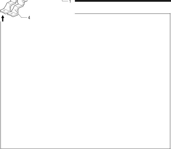
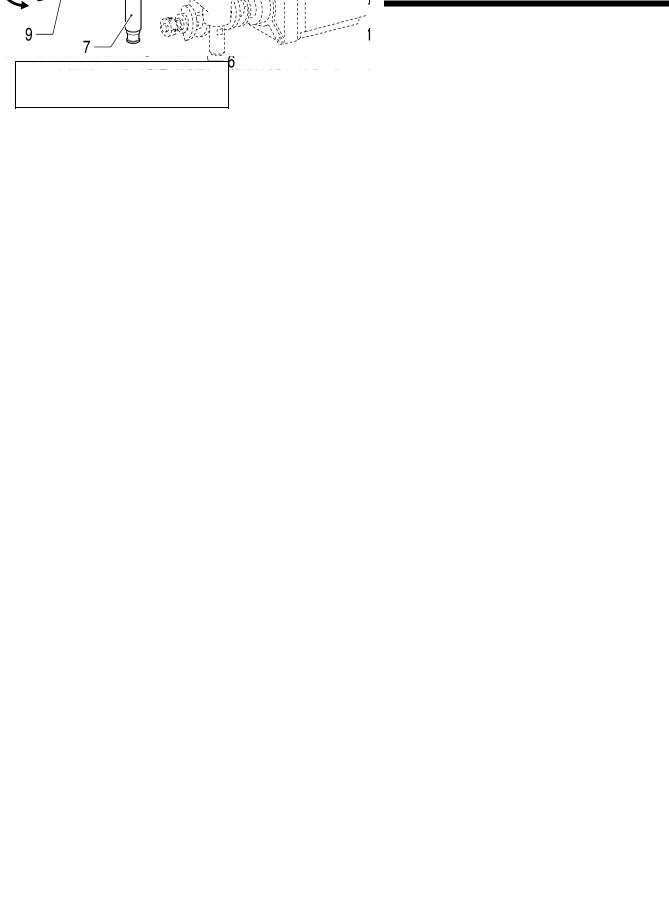
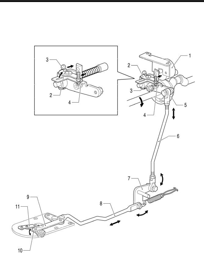
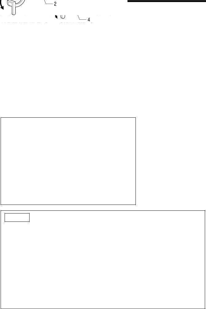
- . Work clamp lifter mechanism
3244Q
1.Work clamp solenoid
2.Plunger
3.Link assy, C
4.Link shaft, B
5.Link, B
6.Link shaft, C
7.Work clamp plate
8.Work clamp arm lever plate
9.Work clamp arm lever shaft 10.Work clamp arm lever 11.Work clamp
*When the presser solenoid is turned off, the presser plate rises, and work clamps lower.
|
|
|
|
|
|
|
|
|
|
|
|
|
KE-432B, 432C |
|
|
|
|
|
BE-438B, 438C |
|
|
||
|
|
|
|
|
|
|
|
|
|
||
|
|
|
|
|
|
||||||
|
|
|
|
|
|
|
|
|
|
|
|
|
|
|
|
|
|
|
|
||||
|
|
|
|
|
|
|
|
|
|
|
|
|
|
|
|
|
|
|
|
||||
|
|
|
|
|
|
|
|
|
|
|
|
|
|
|
|
|
|
|
|
||||
|
|
|
|
|
|
|
7. |
Work clamp lifting rod |
|||
7. |
Work clamp lifting rod |
||||||||||
8. |
Work clamp lifter lever |
8. |
Button clamp lifting lever |
||||||||
9. |
Presser adjusting plate assy |
9. |
Button clamp holder hook assy |
||||||||
10. |
Button clamp holder shaft |
10. |
Button clamp holder shaft |
||||||||
11. |
Work clamp |
11. |
Button clamp |
||||||||
3266Q |
|
|
|
|
|
|
|
|
3267Q |
||
KE-430B, 430C series |
10 |
2. MECHANICAL DESCRIPTIONS
3245Q
Pneumatic specifications
1. Air cylinder
2. Work clamp arm lever shaft
3. Work clamp arm lever
4. Work clamp
11 |
KE-430B, 430C series |
2. MECHANICAL DESCRIPTIONS
- . Work clamp open-close mechanism (KE-432B, 432C)
1. Solenoid assy
2. OY solenoid pin
3. Sensor plate
3262Q 4. Work clamp carrier rod assy
5. Lever
6. Roller
7. Work clamp carrier plate
8. Work clamp guide plate
9. Screw 10.Work clamp
KE-430B, 430C series |
12 |

2. MECHANICAL DESCRIPTIONS
- . Thread wiper mechanism
3246Q
When the presser solenoid is turned off, the presser plate rises, and thread wiper operates in the opposite direction.
1. Work clamp solenoid
2. Plunger
3. Link assy, C
4. Link shaft, B
5. Thread wiper driving lever
6. Thread wiper rod assy
7. Thread wiper arm assy
8. Thread wiper
Solenoid type thread wiper |
3247Q |
|
1. Thread wiper solenoid
2. Thread wiper connecting rod assy
3. Thread wiper arm assy
4. Thread wiper
13 |
KE-430B, 430C series |
2. MECHANICAL DESCRIPTIONS
Stepping foot specifications
1. Thread wiper solenoid
2. Thread wiper connecting rod assy
3. Thread wiper arm assy
4. Thread wiper
3248Q
KE-484C
1. Thread wiper cylinder
2. Thread wiper connecting rod lever
3. Thread wiper connecting rod
4. Thread wiper arm assy
5. Thread wiper
3249Q
KE-430B, 430C series |
14 |

2. MECHANICAL DESCRIPTIONS
- . Feed mechanism
Sewing patterns are created through combinations of X and Y movements.
KE-430B, 431B, 432B, 433B, BE-438B
KE-430C, 431C, 432C, BE-438C
X direction
3250Q
Y direction
3251Q
1.Pulse motor, X
2.Coupling hub, 6.35
3.Coupling spacer
4.Coupling hub, 8
5.Feed cam, X
6.Feed cam roller
7.X-feed lever
8.Tack length regulator block assy
9.Feed bracket
1.Pulse motor, Y
2.Coupling hub, 6.35
3.Coupling spacer
4.Coupling hub, 8
5.Feed cam, Y
6.Feed cam roller
7.Y-feed lever
8.Tack width feed shaft
9.Feed bracket
15 |
KE-430B, 430C series |
2. MECHANICAL DESCRIPTIONS
KE-434B, 435B, 436B
KE-434C, 435C, 436C, 484C
X direction
3252Q
Y direction
3253Q
1.Pulse motor, X
2.Coupling hub, 8
3.Coupling spacer
4.Coupling hub, 8
5.Feed cam, X
6.Feed cam roller
7.X-feed lever
8.Tack length regulator block assy
9.Feed bracket
1.Pulse motor, Y
2.Coupling hub, 8
3.Coupling spacer
4.Coupling hub, 8
5.Feed cam, Y
6.Feed cam roller
7.Y-feed lever
8.Tack width regulator block assy
9.Feed bracket
KE-430B, 430C series |
16 |
2. MECHANICAL DESCRIPTIONS
- . Thread trimmer mechanism
1. Thread trimmer solenoid
2. Driving lever push lever
3. Thread driving lever
3254Q 4. Thread trimmer roller
5. Thread trimmer cam
6. Thread trimmer rod
7. Thread trimmer lever
8. Connecting rod lever assy
9. Thread trimmer connecting rod
10. Movable knife
11. Fixed knife
17 |
KE-430B, 430C series |

2. MECHANICAL DESCRIPTIONS
KE-484C
1. Thread trimmer solenoid
2. Driving lever push lever
3. Thread driving lever
4. Thread trimmer roller
5. Thread trimmer cam
6. Thread trimmer rod
7. Thread trimmer lever
8. Thread trimmer rod, L
9. Thread trimmer connecting rod
10. Movable knife
11. Thread trimmer cylinder
12. Extension rod
13. Fixed knife
3255Q
KE-430B, 430C series |
18 |
2. MECHANICAL DESCRIPTIONS
- . Thread nipper mechanism
Manual operation
1. Lifting lever
2. Lifting crank
3. Tension release lever
4. Tension release stud
5. Tension release pin
3256Q
In thread trimming
3257Q
1. Thread trimmer solenoid |
7. |
Tension release driving lever |
|
2. Driving lever push lever |
8. |
Tension release lever, U |
|
3. Thread driving lever |
9. |
Tension release rod assy |
|
4. Tension release driving lever |
10. |
Tension release lever |
|
5. Lower thread retainer collar |
11. |
Tension release stud |
|
6. Thread trimmer cam |
12. |
Tension release pin |
|
19 |
KE-430B, 430C series |
2. MECHANICAL DESCRIPTIONS
KE-484C
1. Tension release cylinder
2. Tension release pin push lever
3. Tension release pin, L
4. Tension release pin
3258Q
KE-430B, 430C series |
20 |
2. MECHANICAL DESCRIPTIONS
- . Thread take-up mechanism
3259Q
Stepping foot specifications
1. Thread take-up solenoid
2. Solenoid joint
3. Thread take-up lever crank
4. Thread take-up lever
3260Q
3261Q
KE-484C
1. Thread take-up cylinder
2. Thread take-up lever
21 |
KE-430B, 430C series |
3. DISASSEMBLY
. DISASSEMBLY
 CAUTION
Disassembly should only be carried out by a qualified technician.
Turn off the power switch before disassembly, otherwise the machine may operate if the foot switch is depressed by mistake, which could result in injury.
Be sure to wear protective goggles and gloves when handling the lubricating oil and grease, so that they do not get into your eyes or onto your skin, otherwise inflammation can result.
Furthermore, do not drink the oil or eat the grease under any circumstances, as they can cause vomiting and diarrhea.
Keep the oil out of the reach of children.
Disassemble each part in order of the numbers.
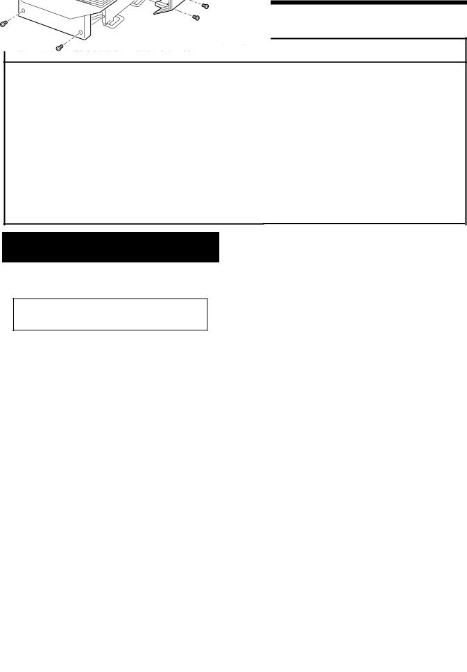
- . Covers
KE-430B, 431B, 432B, 433B, BE-438B KE-430C, 431C, 432C, BE-438C
Disconnect the air hoses from the air supply and wait for the needle on the pressure gauge to drop to “0” before disassembly of any parts which use the pneumatic equipment.
Use only the proper replacement parts as specified by Brother.
If any safety devices have been removed, be absolutely sure to re-install them to their original positions and check that they operate correctly before using the machine.
Any problems in machine operation which result from unauthorized modifications to the machine will not be covered by the warranty.
3269Q
1. Top cover
2. Belt cover
3. Frame side cover
4. Bed cover, LF
5. Bed cover, LR
6. Bed cover, R
7. Eye guard assy
8. Face plate assy
9. Shuttle race cover assy
3268Q
KE-430B, 430C series |
22 |
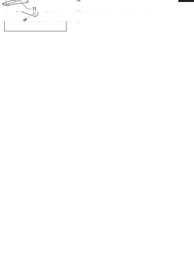
3. DISASSEMBLY
KE-434B, 435B, 436B KE-434C, 435C, 436C, 484C
<KE-435B, 435C> <KE-436B, 436C>
3269Q
3270Q
1.Top cover
2.Belt cover
3.Frame side cover
4.Bed cover, LF
5.Bed cover, LR
6.Bed cover, R
7.Eye guard assy
8.Bolts [2 pcs]
9.Face plate assy
10.Shuttle race cover assy
11.Auxiliary plate supports [2 pcs]
12.Needle plate auxiliary plate
13.Auxiliary plate supports [4 pcs]
23 |
KE-430B, 430C series |
Loading...