


Brother Fax875MC, Fax825MC, Fax590MC, Fax590DT, Fax725M Service Manual
...FACSIMILE EQUIPMENT
SERVICE MANUAL
MODEL: FAX100/570/615/625/635/675
FAX575M/715M/725M
FAX590DT/590MC/825MC/875MC
© Copyright Brother 1995
All rights reserved.
No part of this publication may be reproduced in any form or by any means without permission in writing from the publisher.
Specifications are subject to change without notice.
PREFACE
This publication is a Service Manual covering the specifications, construction, theory of operation, and maintenance of the Brother facsimile equipment. It includes information required for field troubleshooting and repair—disassembly, reassembly, and adjustment—so that service personnel will be able to understand equipment function, to rapidly repair the equipment and order any necessary spare parts.
To perform appropriate maintenance so that the facsimile equipment is always in best condition for the customer, the service personnel must adequately understand and apply this manual.
This manual is made up of five chapters and appendices.
CHAPTER I. |
GENERAL DESCRIPTION |
CHAPTER II. |
INSTALLATION |
CHAPTER III. |
THEORY OF OPERATION |
CHAPTER IV. |
INDICATION AND INFORMATION PRINTOUT OF ERROR |
CHAPTER V. |
MAINTENANCE |
APPENDICES |
Circuit Diagrams |
This manual describes the model and its versions to be destined for major countries. The specifications and functions are subject to change depending upon each destination.
CHAPTER I.
GENERAL DESCRIPTION
CONTENTS
1. |
EQUIPMENT OUTLINE ................................................................................. |
I-1 |
|
|
1.1 |
External Appearance .............................................................................. |
I-1 |
|
1.2 |
Components ............................................................................................ |
I-1 |
2. |
SPECIFICATIONS .......................................................................................... |
I-2 |
|

1. EQUIPMENT OUTLINE
1.1External Appearance
The figure below shows the equipment appearance and approximate dimensions.
121 (H)
304 (D)
377 (W)
(Unit: mm)
1.2Components
The equipment has the following components:
Facsimile |
|
|
|
Electronic/ |
|
|
Main PCB |
|
|
|
|
|
|||
Equipment |
|
Electrical/ |
|
NCU PCB |
|||
|
|
|
|
Section |
|
||
|
|
|
|
||||
|
|
|
|
|
|
|
Control Panel PCB |
|
|
|
|
|
|
|
|
|
|
|
|
|
|
|
Recording Head Unit |
|
|
|
|
|
|
|
|
|
|
|
|
|
|
|
LED Array (for illuminating documents) |
|
|
|
|
|
|
|
|
|
|
|
|
|
|
|
Charge Coupled Device (CCD) Unit |
|
|
|
|
|
|
|
|
|
|
|
|
|
|
|
Sensors |
|
|
|
|
|
|
|
|
|
|
|
|
Mechanical |
|
|
Power Supply PCB |
|
|
|
|
|
|
||
|
|
|
|
|
|
Recorder & Cutter Unit |
|
|
|
|
|
|
|
||
|
|
|
|
Section |
|
CCD Unit |
|
|
|
|
|
|
|
|
|
|
|
|
|
|
|
|
|
|
|
|
|
|
|
|
Drive Motor (for paper & document feed and for cutter drive) |
|
|
|
|
|
|
|
|
|
|
|
|
|
|
|
Clutch Solenoid |
|
|
|
|
|
|
|
|
|
|
|
|
|
|
|
Drive Gears |
|
|
|
|
|
|
|
|
|
|
|
|
|
|
|
Control Panel Unit |
|
|
|
|
|
|
|
|
Package |
|
|
|
|
Covers |
||
|
|
|
|
||||
|
|
|
|
Automatic Document Feeder (ADF) |
|||
|
|
|
|
||||
Accessories |
|
|
|
|
Handset |
||
|
|
|
|
||||
|
|
|
|
|
|
|
Frame and Miscellaneous Parts |
|
|
|
|
|
|
|
|
I –1
2. SPECIFICATIONS
Model |
|
FAX100 |
FAX615 |
FAX625 |
FAX635 |
FAX675 |
Color |
|
1138 |
BN4 |
BN2 |
BN4 |
BN2 |
Modem Speed |
|
9600 bps |
9600 bps |
9600 bps |
9600 bps |
9600 bps |
Coding Method |
|
MH |
MH |
MH |
MH |
MH |
Transmission Speed |
15 sec |
15 sec |
15 sec |
15 sec |
15 sec |
|
CCITT Group |
|
G3 |
G3 |
G3 |
G3 |
G3 |
Input/Output Width |
8.5"/8.5" |
8.5"/8.5" |
8.5"/8.5" |
8.5"/8.5" |
8.5"/8.5" |
|
Auto Cutter |
|
Yes |
Yes |
Yes |
Yes |
Yes |
ADF Capacity (pages) |
15 |
15 |
15 |
15 |
15 |
|
Anti-curl System |
|
Yes |
Yes |
Yes |
Yes |
Yes |
Paper Size (Standard thermal/Therma PLUS) |
164'/164' |
164'/164' |
164'/164' |
164'/164' |
164'/164' |
|
LCD Size |
|
16 x 1 |
16 x 1 |
16 x 1 |
16 x 1 |
16 x 1 |
On-screen Programming |
Yes |
Yes |
Yes |
Yes |
Yes |
|
Super Fine |
|
Yes |
Yes |
Yes |
Yes |
Yes |
Smoothing |
|
Yes |
Yes |
Yes |
Yes |
Yes |
Gray Scale |
|
32 |
32 |
32 |
64 |
64 |
One-touch Dialing |
|
10x2 |
10 |
10x2 |
10x2 |
10x2 |
Speed Dialing |
|
20 |
30 |
20 |
30 |
40 |
Group Dialing |
|
No |
No |
No |
No |
No |
Telephone Index |
|
No |
No |
No |
No |
No |
Speakerphone |
|
Monitor |
Monitor |
Monitor |
Monitor |
Monitor |
Fax/Tel Switch |
|
Yes |
Yes |
Yes |
Yes |
Yes |
TAD Interface |
|
Yes |
Yes |
Yes |
Yes |
Yes |
Enhanced Remote Activation |
Yes |
Yes |
Yes |
Yes |
Yes |
|
Distinctive Ringing |
Yes |
Yes |
Yes |
Yes |
Yes |
|
Next-Fax Reservation |
Yes |
No |
Yes |
Yes |
Yes |
|
Help |
|
Yes |
Yes |
Yes |
Yes |
Yes |
Caller ID |
|
No |
No |
No |
No |
Yes |
Automatic Redialing |
Yes |
Yes |
Yes |
Yes |
Yes |
|
Multi-Resolution Transmission |
Yes |
Yes |
Yes |
Yes |
Yes |
|
Polling |
|
Std/Sec/Del |
Std/Sec/Del |
Std/Sec/Del |
Std/Sec/Del |
Std/Sec/Del |
Delayed Transmission |
Yes, 1 timer |
Yes, 1 timer |
Yes, 1 timer |
Yes, 1 timer |
Yes, 1 timer |
|
Coverpage |
|
Yes |
Yes |
Yes |
Yes |
Yes |
Call Reservation |
|
Yes |
Yes |
Yes |
Yes |
Yes |
Call Back Message |
Yes |
Yes |
Yes |
Yes |
Yes |
|
Activity Report |
|
Yes |
Yes |
Yes |
Yes |
Yes |
Transmission Verification Report |
Yes |
Yes |
Yes |
Yes |
Yes |
|
Page Memory |
|
No |
No |
No |
No |
No |
ECM |
|
No |
No |
No |
No |
No |
Broadcasting |
|
No |
No |
No |
No |
No |
Quick Scanning |
|
No |
No |
No |
No |
No |
Out-of-Paper Reception |
No |
No |
No |
No |
No |
|
Multi Copy |
|
No |
No |
No |
No |
No |
Multi Transmission |
No |
No |
No |
No |
No |
|
TAD Type |
|
No |
No |
No |
No |
No |
ICM Recording Time |
No |
No |
No |
No |
No |
|
Remote Control |
|
No |
No |
No |
No |
No |
Paging |
|
No |
No |
No |
No |
No |
Toll Saver |
|
No |
No |
No |
No |
No |
Memo/2-Way Recording |
No |
No |
No |
No |
No |
|
Time/Date Stamp |
|
No |
No |
No |
No |
No |
Message Center |
|
No |
No |
No |
No |
No |
OGM |
|
No |
No |
No |
No |
No |
FAX Forwarding |
|
No |
No |
No |
No |
No |
FAX Retrieval |
|
No |
No |
No |
No |
No |
PCI (Missing link) (* : w/o PC FAX RX) |
No |
(Note 1) |
(Note 1) |
Option* |
Option* |
|
Password |
|
No |
No |
No |
No |
No |
Paper Save |
|
No |
No |
No |
No |
No |
Day-Night Mode |
|
No |
No |
No |
No |
No |
Elec. Vol. Control |
|
No |
No |
No |
No |
No |
FAX-on-demand |
|
No |
No |
No |
No |
No |
Voice-on-demand |
|
No |
No |
No |
No |
No |
Fax Mail Box |
|
No |
No |
No |
No |
No |
Voice Mail Box |
|
No |
No |
No |
No |
No |
(Note 1) No: |
Asia and Taiwan |
|
|
|
|
|
Option*: Gulf, China, and Saudi Arabia
I –2
Model |
|
|
FAX715M |
FAX725M |
FAX825MC |
FAX875MC |
Color |
|
|
BN2 |
BN4 |
BN2 |
BN2 |
Modem Speed |
|
9600 bps |
14400 bps |
14400 bps |
14400 bps |
|
Coding Method |
|
MH |
MH |
MH |
MH |
|
Transmission Speed |
15 sec |
9 sec |
9 sec |
9 sec |
||
CCITT Group |
|
G3 |
G3 |
G3 |
G3 |
|
Input/Output Width |
8.5"/8.5" |
8.5"/8.5" |
8.5"/8.5" |
8.5"/8.5" |
||
Auto Cutter |
|
Yes |
Yes |
Yes |
Yes |
|
ADF Capacity (pages) |
15 |
15 |
15 |
15 |
||
Anti-curl System |
|
Yes |
Yes |
Yes |
Yes |
|
Paper Size (Standard thermal/Therma PLUS) |
164'/164' |
164'/164' |
164'/164' |
164'/164' |
||
LCD Size |
|
|
16 x 1 |
16 x 1 |
16 x 1 |
16 x 1 |
On-screen Programming |
Yes |
Yes |
Yes |
Yes |
||
Super Fine |
|
Yes |
Yes |
Yes |
Yes |
|
Smoothing |
|
Yes |
Yes |
Yes |
Yes |
|
Gray Scale |
|
64 |
64 |
64 |
64 |
|
One-touch Dialing |
|
10x2 |
10x2 |
10x2 |
10x2 |
|
Speed Dialing |
|
40 |
40 |
40 |
80 |
|
Group Dialing |
|
6 |
6 |
6 |
6 |
|
Telephone Index |
|
Yes |
Yes |
Yes |
Yes |
|
Speakerphone |
|
Monitor |
Monitor |
Monitor |
Monitor |
|
Fax/Tel Switch |
|
Yes |
Yes |
Yes |
Yes |
|
TAD Interface |
|
Yes |
Yes |
Yes |
Yes |
|
Enhanced Remote Activation |
Yes |
Yes |
Yes |
Yes |
||
Distinctive Ringing |
Yes |
(Note 2) |
Yes |
(Note 3) |
||
Next-Fax Reservation |
Yes |
Yes |
Yes |
Yes |
||
Help |
|
|
Yes |
Yes |
Yes |
Yes |
Caller ID |
|
|
Yes |
(Note 2) |
Yes |
(Note 3) |
Automatic Redialing |
Yes |
Yes |
Yes |
Yes |
||
Multi-Resolution Transmission |
Yes |
Yes |
Yes |
Yes |
||
Polling |
|
|
Std/Sec/Del |
Std/Sec/Del |
Std/Sec/Del/Seq |
Std/Sec/Del/Seq |
Delayed Transmission |
Yes, 3 timers |
Yes, 3 timers |
Yes, 3 timers |
Yes, 3 timers |
||
Coverpage |
|
Yes |
Yes |
Yes |
Yes |
|
Call Reservation |
|
Yes |
Yes |
Yes |
Yes |
|
Call Back Message |
Yes |
Yes |
Yes |
Yes |
||
Activity Report |
|
Yes |
Yes |
Yes |
Yes |
|
Transmission Verification Report |
Yes |
Yes |
Yes |
Yes |
||
Page Memory |
|
10 pages |
10 pages |
50 pages |
50 pages |
|
ECM |
|
|
Yes |
Yes |
Yes |
Yes |
Broadcasting |
|
Yes |
Yes |
Yes |
Yes |
|
Quick Scanning |
|
Yes |
Yes |
Yes |
Yes |
|
Out-of-Paper Reception |
Yes |
Yes |
Yes |
Yes |
||
Multi Copy |
|
Yes, w/sort |
Yes, w/sort |
Yes, w/sort |
Yes, w/sort |
|
Multi Transmission |
Yes |
Yes |
Yes |
Yes |
||
TAD Type |
|
No |
No |
IC Digital |
IC Digital |
|
ICM Recording Time |
No |
No |
(18 min) |
(18 min) |
||
Remote Control |
|
No |
No |
Full |
Full |
|
Paging |
|
|
No |
No |
Yes |
Yes |
Toll Saver |
|
No |
No |
Yes |
Yes |
|
Memo/2-Way Recording |
No |
No |
Yes |
Yes |
||
Time/Date Stamp |
|
No |
No |
Yes |
Yes |
|
Message Center |
|
No |
No |
Yes |
Yes |
|
OGM |
|
|
No |
No |
Yes |
Yes |
FAX Forwarding |
|
No |
No |
Yes |
Yes |
|
FAX Retrieval |
|
No |
No |
Yes |
Yes |
|
PCI (Missing link) (* : w/o PC FAX RX) |
Option |
Option |
Option |
Option |
||
Password |
|
No |
No |
No |
No |
|
Paper Save |
|
No |
No |
No |
No |
|
Day-Night Mode |
|
No |
No |
No |
No |
|
Elec. Vol. Control |
|
No |
No |
No |
No |
|
FAX-on-demand |
|
|
|
Yes |
Yes |
|
Voice-on-demand |
|
No |
No |
Yes |
Yes |
|
Fax Mail Box |
|
No |
No |
Yes, 5 |
Yes, 5 |
|
Voice Mail Box |
|
No |
No |
Yes, 5 |
Yes, 5 |
|
(Note 2) |
No: |
Taiwan |
|
|
|
|
|
Yes: |
Other countries |
|
|
|
|
(Note 3) |
No: |
Asia, Gulf, China, and Saudi Arabia |
|
|
|
|
|
Yes: |
Other countries |
|
|
|
|
I –3
Model |
FAX570 |
FAX575M |
FAX590DT/590MC |
||
Color |
1138/1293 (Note 4) |
1138/1293 (Note 4) |
1138/1293 (Note 4) |
|
|
Modem Speed |
9600 bps |
9600 bps |
14400 bps |
||
Coding Method |
MH |
MH |
MH |
||
Transmission Speed (Brother chart) |
15 sec |
13 sec |
9 sec |
||
(ITU-T No. 1 chart) |
19 sec |
15 sec |
10 sec |
||
CCITT Group |
G3 |
G3 |
G3 |
||
Input/Output Width |
A4/A4 |
A4/A4 |
A4/A4 |
||
Auto Cutter |
Yes |
Yes |
Yes |
||
ADF Capacity (pages) |
15 |
15 |
15 |
|
|
Anti-curl System |
Yes |
Yes |
Yes |
||
Paper Size (Standard thermal/Therma PLUS) |
50 m/50 m |
50 m/50 m |
50 m/50 m |
||
LCD Size |
16 x 1 |
16 x 1 |
16 x 1 |
||
On-screen Programming |
Yes |
Yes |
Yes |
||
Super Fine |
Yes |
Yes |
Yes |
||
Smoothing |
Yes |
Yes |
Yes |
|
|
Gray Scale |
32 |
64 |
64 |
|
|
One-touch Dialing |
10x2 |
10x2 |
10x2 |
||
Speed Dialing |
40 |
40 |
40 |
|
|
Group Dialing |
None |
6 |
6 |
|
|
Telephone Index |
No |
Yes |
Yes |
||
Speakerphone |
No |
No |
No |
||
Fax/Tel Switch |
Yes |
Yes |
Yes |
||
TAD Interface |
Yes |
Yes |
Yes |
||
Enhanced Remote Activation |
Yes |
Yes |
Yes |
||
Next-Fax Reservation |
Yes |
Yes |
Yes |
||
Help |
Yes |
Yes |
Yes |
||
Caller ID |
UK/Holland/Sweden |
UK |
UK/Holland/Sweden |
||
Automatic Redialing |
Yes |
Yes |
Yes |
||
Multi-Resolution Transmission |
Yes |
Yes |
Yes |
||
Polling |
Std/Sec/Del |
Std/Sec/Del |
Std/Sec/Del/Seq |
||
Delayed Transmission |
Yes, 1 timer |
Yes, 3 timers |
Yes, 3 timers |
||
Coverpage |
Yes |
Yes |
Yes |
||
Call Reservation |
Yes |
Yes |
Yes |
||
Call Back Message |
Yes |
Yes |
Yes |
||
Journal Report (Activity Report) |
Yes |
Yes |
Yes |
||
Transmission Verification Report |
Yes |
Yes |
Yes |
||
Page Memory (Brother chart) |
No |
10 pages |
55 pages |
||
(CCITT No. 1 chart) |
No |
9 pages |
49 pages |
||
ECM |
No |
Yes |
Yes |
||
Broadcasting |
No |
60 |
60 |
|
|
Quick Scanning |
No |
No |
No |
||
Out-of-Paper Reception |
No |
Yes |
Yes |
||
Multi Copy |
No |
Yes, w/stack & sort |
Yes, w/stack & sort |
||
Multi Transmission |
No |
Yes |
Yes |
||
TAD Type |
No |
No |
IC Digital |
||
ICM Recording Time |
No |
No |
13 min |
||
Remote Control |
No |
No |
Yes |
||
Paging |
No |
No |
Yes |
||
Toll Saver |
No |
No |
Yes |
||
Time/Date Stamp |
No |
No |
Yes |
||
Message Center |
No |
No |
Yes |
||
OGM |
No |
No |
Yes |
||
FAX Forwarding |
No |
No |
Yes |
||
FAX Retrieval |
No |
No |
Yes |
||
Connect 5000 Connectivity |
No |
Yes |
Yes |
||
(PCI or Missing link) (* : w/o PC FAX RX) |
|||||
|
|
|
|
||
Backup for Voice |
No |
No |
6 hours |
||
Backup for Page Memory |
No |
No |
6 hours |
||
Backup for Clock |
15 hours |
15 hours |
15 hours |
||
Password |
No |
No |
No |
||
FAX-on-demand |
No |
No |
Up to 50 messages |
||
Voice-on-demand |
No |
No |
Up to 50 messages |
||
Fax Mail Box |
No |
No |
Yes, 5 |
||
Voice Mail Box |
No |
No |
Yes, 5 |
||
(Note 4) 1293: German and UK versions 1138: Other versions
I –4
CHAPTER II.
INSTALLATION
CHAPTER III.
THEORY OF OPERATION
CONTENTS
1. |
OVERVIEW |
..................................................................................................... |
III-1 |
||
|
1.1 |
Mechanical Layout ................................................................................. |
III-1 |
||
|
1.2 |
Functional Block Diagram ...................................................................... |
III-1 |
||
2. |
MECHANISMS ................................................................................................ |
III-2 |
|||
|
2.1 |
Transmitting Mechanism (Feeding and Scanning Documents) .............. |
III-2 |
||
|
|
2.1.1 Automatic document feeder (ADF) .................................................. |
III-2 |
||
|
|
2.1.2 |
Scanner ........................................................................................... |
III-2 |
|
|
2.2 |
Receiving Mechanism (Feeding Recording Paper & Recording Data) ... |
III-3 |
||
|
|
2.2.1 |
Anti-curl system (ACS) .................................................................... |
III-3 |
|
|
|
2.2.2 |
Automatic cutter .............................................................................. |
III-3 |
|
|
2.3 |
Sensors ................................................................................................... |
III-4 |
||
|
2.4 |
Power Transmission Shift by the Planetary Gear Train and |
|
||
|
|
Clutch Solenoid ....................................................................................... |
III-6 |
||
|
|
2.4.1 Description of planetary gear train .................................................. |
III-6 |
||
|
|
2.4.2 |
Power transmission for four operation modes ................................. |
III-7 |
|
|
|
[ 1 ] |
Recording mode (Solenoid: OFF, Motor rotation: Forward) ........ |
III-7 |
|
|
|
[ 2 ] |
Scanning mode (Solenoid: OFF, Motor rotation: Reverse) .......... |
III-8 |
|
|
|
[ 3 ] |
Copying mode (Solenoid: ON OFF, Motor rotation: Forward) . |
III-8 |
|
|
|
[ 4 ] |
Cutter driving mode (Solenoid: ON, Motor rotation: Reverse) ..... |
III-9 |
|
|
|
2.4.3 |
Power transmission route ............................................................... |
III-10 |
|
3. |
CONTROL ELECTRONICS ........................................................................... |
III-11 |
|||
|
3.1 |
Configuration ........................................................................................... |
III-11 |
||
|
3.2 |
Main PCB ................................................................................................ |
III-11 |
||
|
|
3.2.1 |
FAX100/570/615/625/635/675/575M/715M .................................... |
III-12 |
|
|
|
[ 1 ] |
Primary function group ................................................................ |
III-12 |
|
|
|
[ 2 ] |
ROM and DRAM group ............................................................... |
III-13 |
|
|
|
[ 3 ] |
Image processing group ............................................................. |
III-14 |
|
|
|
[ 4 ] |
Analog signal processing group .................................................. |
III-15 |
|
|
|
3.2.2 |
FAX725M/590DT/590MC/825MC/875MC ....................................... |
III-16 |
|
|
|
[ 1 ] |
Primary function group ................................................................ |
III-16 |
|
|
|
[ 2 ] |
DRAM group ............................................................................... |
III-17 |
|
|
[ 3 |
] |
Image processing group ............................................................. |
III-18 |
|
[ 4 |
] |
Analog signal processing group .................................................. |
III-19 |
|
[ 5 |
] MODEM ....................................................................................... |
III-20 |
|
3.3 |
NCU PCB ................................................................................................ |
III-21 |
||
3.4 |
Control Panel PCB ................................................................................. |
III-23 |
||
3.5 |
Power Supply .......................................................................................... |
III-24 |
||

1. OVERVIEW
1.1Mechanical Layout
Recording paper cover
Panel cover ASSY
Recorder & cutter unit
Main frame
Drive unit
Scanner frame ASSY
Handset
NCU PCB
Power supply PCB
Handset mount |
Main PCB |
Bottom plate
1.2Functional Block Diagram
|
|
|
|
|
|
|
|
|
|
|
|
|
|
|
|
PCI |
|
|
|
|
|
|
|
|
|
||
|
|
|
|
|
|
|
|
|
|
|
|
|
|
|
|
|
|
|
|
|
|
PC |
|
||||
|
|
|
|
|
|
|
|
|
|
|
|
|
|
|
(Missing link) |
|
|
|
|
|
|
|
|||||
|
|
|
|
|
|
|
|
|
|
|
|
|
|
|
|
|
|
|
|
|
|
|
|
||||
|
|
LCD |
|
|
|
|
|
|
|
|
|
|
|
|
|
|
|
|
|
|
|
|
|
|
|
||
|
|
|
|
|
|
|
|
|
|
|
|
|
|
|
|||||||||||||
|
|
|
|
|
|
|
|
|
|
|
|
|
|
|
|
|
|
|
|
|
|
|
|
|
|
|
|
|
|
|
Control panel |
|
|
|
|
|
|
|
|
|
|
|
|
|
|
Automatic |
|
||||||||
|
|
|
|
|
|
|
|
|
|
|
|
|
|
|
|
|
|
|
|
|
|
|
|
|
cutter |
|
|
|
|
|
|
|
|
|
|
|
|
|
|
|
|
|
|
|
|
|
|
|
|
|
|
|
|
|
|
|
|
|
|
|
|
|
|
|
|
|
|
|
|
|
|
|
|
|
|
|
|
|
|
|
|
|
|
|
|
|
|
|
|
|
|
|
|
|
|
|
|
|
|
|
|
|
|
|
|
|
|
|
|
|
|
|
|
|
Scanner |
|
|
|
|
|
|
|
|
|
Controller |
|
|
|
|
|
|
Recorder |
|
||||||
|
|
|
|
|
|
|
|
|
|
|
|
|
|
|
|
|
|
||||||||||
|
|
|
|
|
|
|
|
|
|
|
|
|
|
|
|
|
|
|
|
|
|
|
|
|
|||
|
|
|
|
|
|
|
|
|
|
|
|
|
|
|
|
|
|
|
|
|
|
|
|
|
|||
|
|
|
|
|
|
|
|
|
|
|
|
|
|
|
|
|
|
|
|
|
|
|
|
|
|
|
|
|
|
|
|
|
|
|
|
|
|
|
|
|
|
|
|
|
|
|
|
|
|
|
|
|
Drive unit |
|
|
|
|
|
|
|
|
|
|
|
|
|
|
|
|
|
|
|
|
|
|
|
|
|
|
|
|
||
|
|
|
|
|
|
|
|
|
|
|
|
|
|
|
|
|
|
|
|
|
|
|
|
|
|
|
|
|
|
|
|
|
|
|
|
|
|
|
|
|
|
|
|
|
|
|
|
|
|
|
|
|
|
|
|
|
|
|
|
|
|
|
|
|
|
|
|
|
|
|
|
|
|
|
|
|
|
|
|
|
|
|
|
Line |
|
|
|
|
|
|
|
NCU |
|
|
|
|
|
|
|
|
|
|
|
|
Power supply |
|
|
||||
|
|
|
|
|
|
|
|
|
|
|
|
|
|
|
|
|
|
|
|
|
|||||||
|
|
|
|
|
|
|
|
|
|
|
|
|
|
|
|
|
|
|
|
|
|
|
|
|
|||
|
|
|
|
|
|
|
|
|
|
|
|
|
|
|
|
|
|
|
|
|
|
|
|
|
|||
|
|
|
|
|
|
|
|
|
|
|
|
|
|
|
|
|
|
|
|
|
|
|
|
|
|
|
|
|
|
|
|
|
|
|
|
|
|
|
|
|
|
|
|
|
|
|
|
|
|
|
|
|
|
|
|
|
|
Telephone |
|
|
|
|
|
|
|
|
|
Speaker |
|
|
|
|
|
|
|
|
|
||||||
|
|
|
|
|
|
|
|
|
|
|
|||||||||||||||||
|
|
|
|
|
|
|
|
|
|
|
|
|
|
|
|
|
|
|
|
||||||||
|
|
|
|
|
|
|
|
|
|
|
|
|
|
|
|
|
|
|
|
|
|
|
|
|
|
|
|
III –1
2. MECHANISMS
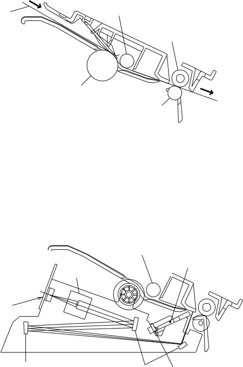
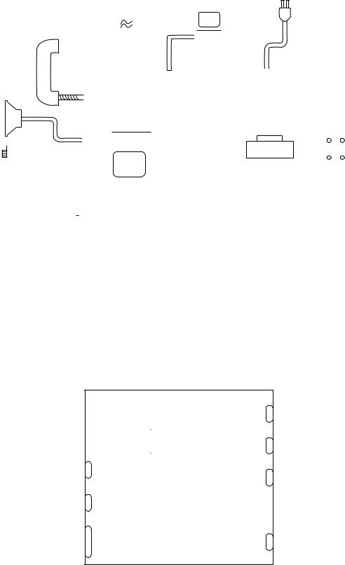
2.1Transmitting Mechanism (Feeding and Scanning Documents)
The transmitting mechanism consists of the document stacker, automatic document feeder (ADF), document feeding related rollers, scanner, and document sensors. (For details about the sensors, refer to Section 2.3.)
If the operator sets documents on the stacker and starts the sending operation, the ADF feeds those documents into the equipment, page by page. Each document advances with the separation roller to the scanner, and then it is fed out of the equipment with the LF roller.
For the drive power source, refer to Section 2.4.
|
Roller (mounted on |
Document |
the panel rear cover) |
|
LF roller ASSY
Separation roller ASSY
(Front)
Pressure roller
2.1.1Automatic document feeder (ADF)
The ADF, which consists of the separation roller and separator, feeds documents set on the document stacker, starting from the bottom sheet to the top, page by page, due to the frictional difference among the separation roller, the documents, and the separator.
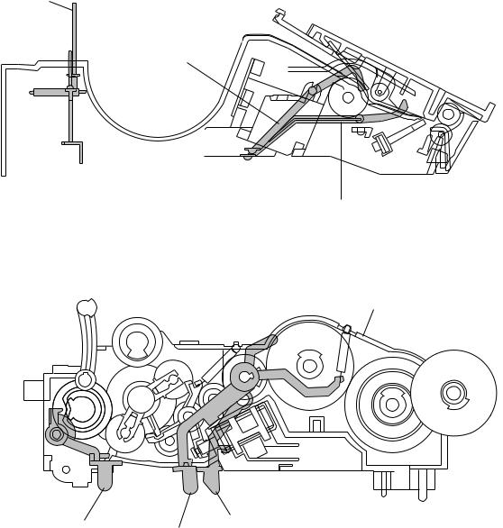
2.1.2Scanner
The scanner uses a charge coupled device (CCD) image sensor.
As shown below, the LED array illuminates a document and the reflected light of the scanned image data is transmitted via the mirrors into the lens which reduces the scanned data so as to form the image on the CCD.
Separation roller ASSY
Bar lens
Lens
CCD PCB
(Front)
Mirror |
Mirrors |
LED array |
|
III –2
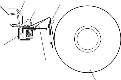
2.2Receiving Mechanism (Feeding Recording Paper & Recording Data)
The receiving mechanism consists of the recording paper roll holder, anti-curl system (ACS), platen, thermal recording head, automatic cutter, and sensors. (For details about the sensors, refer to Section 2.3.)
The recording paper is routed through the ACS to the recording head which prints onto the heat-sensitive recording paper pressed by the platen according to received image signals. The printed paper is further fed through the cutter chute and cut by the automatic cutter page by page.
For the drive power source, refer to Section 2.4.
Cutter chute
ACS rod
Upper blade
Platen
Lower blade |
|
|
|
Recording |
|
(Rear) |
head |
ACS plate |
|
|
Recording paper roll
2.2.1Anti-curl system (ACS)
The ACS eliminates curl peculiar to the rolled recording paper by curving the paper towards the opposite side of the curl with the ACS rod and the ACS plate.
2.2.2Automatic cutter
The automatic paper cutter consists of an upper blade (rotary) and a lower blade (stationary). As the upper blade rotates around the left end as a support, the recording paper will be cut. Upon completion of cutting operation, the upper blade returns to the home position which is detected by the cutter sensor.
III –3
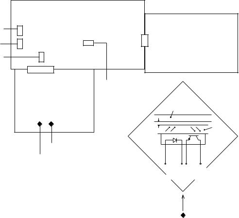
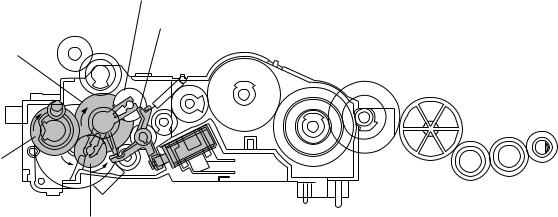
2.3 Sensors
This equipment has two photosensors and four mechanical sensors as described below.
Photosensors
•Document front sensor which detects a presence of documents.
•Document rear sensor which detects the leading and trailing edges of pages to tell the control circuitry when the leading edge of a new page has reached the starting position and when the scan for that page is over.
These two photosensors are located on the main PCB. They are of a reflection type consisting of a light-emitting diode and a light-receiving transistor. Each of them has an actuator separately arranged (see the next page). If an actuator is activated, its white end will come to the path of light issued from the light-emitting diode and reflect its light. The moment the reflected light enters the light-receiving transistor, the sensor signals the detection.
Mechanical sensors
•PE (paper empty) sensor which detects whether the recording paper is present.
•Cover sensor which detects whether the recording paper cover is closed.
•Cutter sensor which detects the home position of the upper rotary blade of the automatic cutter.
•Hook switch sensor which detects whether the handset is placed on the handset mount.
These four sensors are located on the NCU PCB. Each of them has an actuator separately arranged (see the next page). If an actuator is activated, its lower end pushes down the lever provided on the corresponding sensor so that the sensor signals the detection.
|
|
(Rear) |
|
|
|
NCU PCB |
|
Cutter sensor |
SW3 |
|
|
|
SW1 |
|
|
Hook switch |
|
|
|
SW4 |
|
Power supply PCB |
|
sensor |
|
||
Cover sensor |
SW2 |
|
|
|
|
PE sensor |
|
|
|
Main PCB |
|
|
|
|
Path of |
|
|
|
actuator's end |
|
PH1 PH2 |
|
|
|
|
Approx. |
Glass |
|
|
0.7 mm |
|
|
|
|
Document rear sensor
Document front sensor
LightLightemitting receiving diode transistor
III –4
PE sensor actuator
Document front sensor actuator
(Front)
Document rear sensor actuator
Drive unit
(Front)
Cover sensor actuator
Cutter sensor actuator
Hook switch sensor actuator
Location of Sensor Actuators
III –5
2.4Power Transmission Shift by the Planetary Gear Train and Clutch Solenoid
The equipment has a single drive motor whose power transmission route can be switched by the planetary gear train and the clutch solenoid. Accordingly, the equipment mechanism can function in four operation modes (recording, scanning, copying, and cutter driving modes).
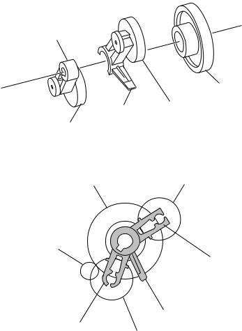
2.4.1Description of planetary gear train
The planetary gear train consists of the sun gear 18/73, two planet gears 20, arm A, and arm B, as shown below.
Arm B
Sun gear 18/73
Planet gear 20A
Arm A
Planet gear 20B
Sun gear 18/73 |
Planet gear 20B |
Motor gear
Arm B
Stopper of arm A
Arm A
Planet gear 20A
If the motor rotates, the sun gear 18/73 rotates so that the rotational force is transmitted to the engagement between the sun gear and the planet gears 20. Since the arms and planet gears are so designed that the moment of the arms is less than that of the planet gears, the arms turn around the center shaft in the same direction as the sun gear 18/73.
If the planet gear(s) becomes engaged with any other gear so that the arm cannot turn furthermore, the rotational force of the sun gear 18/73 is transmitted to that planet gear. Accordingly, the planet gear starts rotation in the opposite direction of the sun gear 18/73.
III –6
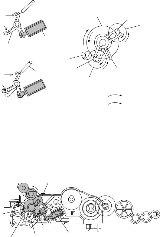
2.4.2Power transmission for four operation modes
Depending upon the clutch solenoid ON/OFF state and the motor rotation direction, the planetary gear train switches the power transmission route for the four operation modes.
Section Y |
|
Sun gear 18/73 |
|
Arm B |
|
|
|
|
Cutout X |
|
Planet gear |
|
|
|
|
|
20B |
Solenoid |
|
|
Clutch lever |
|
|
Solenoid: ON |
|
|
|
Motor gear |
|
Spring |
Arm A |
Stopper of arm A |
|
|
|
Section Y |
|
|
Cutout X |
|
Planet gear 20A |
|
|
|
(engaged |
|
|
with stopper |
|
|
of arm A) |
|
Forward |
|
|
|
Solenoid: OFF |
|
Reverse |
|
|
|
[ 1 ] Recording mode (Solenoid: OFF, Motor rotation: Forward)
In the recording mode, the control system deactivates the clutch solenoid (see the above figure, Solenoid: OFF). Therefore, when the motor rotates in the forward direction, the clutch lever turns clockwise with the spring and its cutout X becomes engaged with the stopper of arm A. Once arm A is locked, the planet gear 20A (C2) will not be engaged with any other gear but simply idle.
The motor rotation turns the sun gear 18/73 (B) counterclockwise so that the planet gear 20B (C1) transmits the rotation to the platen gear (E) via the gear D.
E (Platen gear) |
C1 (Planet gear 20B) |
|
D |
(Front)
B (Sun gear |
F |
|
|
|
|
18/73) |
|
|
|
Cutout X of |
|
|
clutch lever |
Clutch |
|
C2 (Planet |
|
A (Motor gear) |
solenoid |
|
|
gear 20A) |
|
III –7
[ 2 ] Scanning mode (Solenoid: OFF, Motor rotation: Reverse)
Just as in the recording mode, the control system deactivates the clutch solenoid in the scanning mode to lock arm A.
The motor rotates in the reverse direction and the sun gear 18/73 (B) rotates clockwise so that the planet gear 20A (C2) transmits the rotation to the separation roller gear (L) and LF roller gear (O) via the several gears.
C2 (Planet
|
gear 20A) |
I |
|
|
|
|
H |
J |
K |
L (Separation |
(Front) |
|
|
|
roller gear) |
|
|
|
G |
|
|
|
|
|
|
|
|
M |
N |
|
|
|
|
|
|
B (Sun gear |
|
|
|
|
|
18/73) |
|
|
|
|
|
|
F |
|
|
|
O (LF roller |
A (Motor gear) |
|
|
|
gear) |
|
Cutout Xof |
Clutch solenoid |
|
|
|
|
|
|
|
|
||
|
clutch lever |
|
|
|
|
|
|
|
|
|
[ 3 ] Copying mode (Solenoid: ON OFF, Motor rotation: Forward)
The control system at first activates the clutch solenoid to release the stopper of arm A from coutout X of the clutch lever while rotating the motor in the forward direction. Accordingly, the sun gear 18/73 (B) rotates counterclockwise so that both the planet gears 20B (C1) and 20A (C2) transmit the rotation to the platen gear (E) and the roller gears (separation roller gear and LF roller gear), respectively.
Once the planet gear 20A becomes engaged with the gear P, the control system deactivates the clutch solenoid.
E (Platen gear) |
|
C1 (Planet gear 20B) |
|
|
|
|
D |
I |
|
|
|
|
|
|
|
|
|
|
|
H |
K |
L (Separation |
(Front) |
|
|
|
|||
|
|
|
J |
roller gear) |
|
|
|
|
|
||
|
|
G |
|
|
|
|
|
|
|
M |
N |
|
|
F |
|
|
|
B (Sun gear |
|
|
|
|
|
|
|
|
|
|
|
18/73) |
|
|
|
|
|
|
|
P |
|
|
O (LF roller |
|
Clutch lever |
|
|
gear) |
|
A (Motor gear) |
|
|
|
||
C2 (Planet gear 20A)
III –8
[ 4 ] Cutter driving mode (Solenoid: ON, Motor rotation: Reverse)
The control system activates the clutch solenoid to release the stopper of arm A from cutout X of the clutch lever. When the motor rotates in the reverse direction, the sun gear 18/73
(B) rotates clockwise so that the planet gear 20A (C2) transmits the rotation to the cutter gear (Q).
Since the planet gear 20B (C1) is blocked by section Y of the clutch lever, it remains idling without engaging with any other gear.
C1 (Planet gear 20B)
Section Yof clutch lever
B(Sun gear 18/73)
(Front)
Q (Cutter
gear)
C2 (Planet gear 20A)
III –9

2.4.3Power transmission route
Rotation of the motor gear is transmitted as shown below.
E
D |
C1 |
|
|
|
|
|
L |
|
|
|
I |
|
|
|
|
|
J |
|
|
B |
H |
|
K |
|
G |
|
|
||
|
|
O |
||
Q |
|
|
||
F |
|
|
|
|
|
|
|
|
|
|
P |
|
M |
N |
A |
|
|
|
|
C2 |
|
|
|
|
A: |
Motor gear |
I: |
Gear 44A |
|
B: |
Sun gear 18/73 |
J: |
Gear 21/50 |
|
C1: |
Planet gear 20B |
K: |
Gear 44B |
|
C2: |
Planet gear 20A |
L: |
Separation roller gear |
|
D: |
Gear 18/26 |
M: |
Idle gear 24A |
|
E: |
Platen gear |
N: |
Idle gear 24B |
|
F: |
Gear 16A |
O: |
LF roller gear |
|
G: |
Gear 16B |
P: |
Gear 16C |
|
H: |
Gear 24 |
Q: |
Cutter gear |
|
[ 1 ] Recording Mode (Solenoid: OFF, Motor rotation: forward)
C1 D E
A B
C2 (idling)
[ 2 ] Scanning Mode (Solenoid: OFF, Motor rotation: reverse)
C1 (idling)
A B
C2 F G H I J K L M N O
[ 3 ] Copying Mode (Solenoid: ON OFF, Motor rotation: forward)
C1 D E
A B
C2 P F G H I J K L M N O
[ 4 ] Cutter Driving Mode (Solenoid: ON, Motor rotation: reverse)
C1 (idling)
A B
C2 Q
III –10
3. CONTROL ELECTRONICS
3.1Configuration
The hardware configuration of the facsimile equipment is shown below.
|
|
|
|
|
|
|
|
|
|
|
|
|
|
|
|
|
|
Line |
|
|
|
|
|
|
|
|
|
|
|
|
|
*1 On the NCU PCB are the |
||||||
|
|
|
|
|
|
|
|
|
|
|
|
|
|
|
|
|
|
|
|
|
|
|
|
|
|
|
|
|
|
|
following switches: |
|||||||
|
|
|
|
|
|
|
|
|
|
|
|
|
|
|
|
|
|
|
|
|
|
|
|
|
|
|
|
|
|
|
|
|
|
|
||||
|
|
|
|
|
Handset |
|
|
|
|
|
|
|
|
|
|
|
|
|
|
|
|
|
|
|
|
|
|
|
|
|
• PE sensor (SW1) |
|||||||
|
|
|
|
|
|
|
|
|
|
|
|
|
|
|
|
|
|
|
|
|
|
|
|
|
|
|
|
|
|
|||||||||
|
|
|
|
|
|
|
|
|
|
|
|
|
|
|
|
|
|
|
|
|
PC |
|
|
|
|
|
|
|||||||||||
|
|
|
|
|
|
|
|
|
|
|
|
|
|
|
|
|
|
|
|
|
|
|
|
|
|
|
|
|
|
|
|
• Cover sensor (SW2) |
||||||
|
|
|
|
|
|
|
|
|
|
|
|
|
|
|
|
|
|
|
|
|
|
|
|
|
|
|
|
|
|
|
|
|
|
|
• Cutter sensor (SW3) |
|||
|
|
|
|
|
|
|
|
|
|
|
|
|
|
|
|
|
|
|
|
|
|
|
|
|
|
|
|
|
|
|
|
|
|
|
• Hook switch sensor (SW4) |
|||
|
|
|
|
|
|
|
|
|
|
|
|
|
|
|
|
|
|
|
|
|
|
|
|
|
|
|
|
|
|
|
|
|
|
|
*2 On the main PCB are the |
|||
|
|
|
|
|
|
|
|
|
|
|
|
|
|
|
|
|
|
|
|
|
|
|
|
|
|
|
|
|
|
|
Power |
|
|
|||||
|
|
|
|
|
|
|
|
|
|
|
|
|
|
2-pin 2-pin |
|
8-pin |
|
|
|
|
|
|
following photosensors: |
|||||||||||||||
Speaker |
|
|
|
|
|
8-pin |
|
supply |
|
|
||||||||||||||||||||||||||||
|
|
|
|
|
|
|
|
|
|
|
|
|
|
|
|
|
|
• Document front sensor |
||||||||||||||||||||
|
|
|
|
|
|
|
|
|
|
|
|
|
|
|
4-pin |
|
|
|
|
|
|
|
|
|
PCB |
|
||||||||||||
|
|
|
|
|
|
|
|
|
|
|
|
|
|
|
|
|
|
|
|
|
|
*1 |
|
|
|
|
|
|
|
|
|
|
(PH1) |
|||||
|
|
|
|
|
|
|
|
|
|
|
|
|
|
|
|
|
|
|
|
|
|
|
|
|
|
|
|
|
|
|
|
|||||||
|
|
|
|
|
|
|
|
|
|
|
|
|
|
|
|
|
|
26-pin |
|
NCU PCB |
|
|
|
|
|
14-pin |
• Document rear sensor (PH2) |
|||||||||||
|
|
|
|
|
|
|
|
|
|
|
|
|
|
|
|
|
|
|
|
|
|
|
|
|
|
|
|
|
|
|
||||||||
|
|
|
|
|
|
|
|
|
|
|
|
|
|
|
|
|
|
|
|
|
|
|
|
|
|
|
|
|
|
|
|
|
|
|
|
|
|
|
|
|
|
|
|
|
|
|
|
|
|
|
|
2-pin |
|
|
|
|
|
|
|
|
|
|
LCD |
|
|
LEDs |
|
||||||||||
|
|
|
|
|
|
|
|
|
|
|
|
|
6-pin |
(See NOTE |
5-pin |
|
|
|
|
|||||||||||||||||||
|
|
|
|
|
|
|
|
|
|
|
|
|
|
|
|
|
FAX |
|
|
|
|
|
|
|
|
|
|
|
|
|
||||||||
Motor |
|
|
|
|
|
|
|
|
2-pin engine |
below.) |
|
|
|
|
|
|
|
|
|
|
|
|
|
|||||||||||||||
|
|
|
|
|
|
|
|
|
|
|
|
|
|
|
|
|
|
|
|
|
||||||||||||||||||
|
|
|
|
|
|
|
|
|
|
|
|
|
|
|
|
|
|
|
|
|
||||||||||||||||||
|
|
|
|
Solenoid |
|
|
|
|
|
|
12-pin |
*2 |
|
|
|
|
|
|
|
|
|
|
|
|
|
|||||||||||||
|
|
|
|
|
|
|
|
|
|
|
|
|
|
|
|
|
|
|
|
|
|
|
||||||||||||||||
|
|
|
|
|
|
|
|
|
|
|
|
|
2-pin |
Main PCB |
10-pin |
|
CCD |
|
|
13-pin |
||||||||||||||||||
|
|
|
|
|
|
|
|
|
|
|
|
|
|
|
|
|
|
|
|
|
|
PCB |
|
|
||||||||||||||
|
|
|
|
|
|
|
|
|
|
|
|
|
|
|
|
|
|
|
|
|||||||||||||||||||
|
|
|
|
|
|
|
|
|
|
|
|
|
|
|
|
|
|
|
|
|
|
|
|
|
|
|
|
|
|
|
||||||||
|
|
|
|
|
|
|
|
|
|
|
|
|
|
|
|
|
LED array |
|
|
|
|
|
|
|
|
|
|
|
|
|
||||||||
|
|
|
|
|
|
|
|
|
|
|
|
|
|
|
|
|
|
|
|
|
|
|
|
|
|
|
|
|
|
|
|
|
|
|
|
|
|
|
|
|
|
|
|
|
|
|
|
|
|
|
|
|
|
|
|
|
|
|
|
|
|
|
|
|
|
|
|
|
|
FPC key |
|
||||||
|
|
|
|
|
|
|
|
|
|
|
|
|
|
|
Thermal recording head |
|
|
|
|
|
|
|
|
|
|
|
|
|
||||||||||
|
|
|
|
|
|
|
|
|
|
|
|
|
|
|
|
|
|
|
|
|
|
|
||||||||||||||||
|
|
|
|
|
|
|
|
|
|
|
|
|
|
|
|
|
|
|
|
|
|
|
|
|
|
|
|
|
|
|
|
|
|
|
|
|
|
|
|
|
|
|
|
|
|
|
|
|
|
|
|
|
|
|
|
|
|
|
|
|
|
|
|
|
|
|
|
|
|
|
|
|
|
|
|
|
|
|
|
|
|
|
|
|
|
|
|
|
|
|
|
|
|
|
|
|
NOTE: The FAX engine includes a CPU and gate array. In the FAX100/570/ |
|||||||||||||||||||
|
|
|
|
|
|
|
|
|
|
|
|
|
|
|
|
|
|
|
|
|
|
|
615/625/635/675/575M/715M, it also includes a MODEM. |
|||||||||||||||
|
|
|
|
|
|
|
|
|
|
|
|
|
|
|
|
|
|
|
|
Configuration of Facsimile Equipment |
|
|
|
|
||||||||||||||
3.2Main PCB
The main PCB, which is the nucleus controlling the entire operation of the equipment, consists of a FAX engine (ASIC), memories, MODEM (except for FAX100/570/615/625/635/675/ 575M/715M), motor drive circuitry, sensor detection circuitry, and analog circuits for scanning, recording, and power transmission switching.
|
|
|
ROM |
|
|
|
|
|
|
Control panel |
|
|
|
|
|
|
|||||
|
|
|
|
|
|
|
||||
|
|
|
|
|
|
|
|
|
|
|
|
|
|
|
|
|
|
|
|
|
|
|
|
|
|
|
|
|
|
|
|
|
|
|
|
E2PROM |
|
|
|
|
|
|
Recording head |
|
|
|
|
|
|
|
|
|||
|
|
|
|
|
|
|
|
|||
|
|
|
|
|
|
|
|
|
|
|
NCU and |
|
|
DRAM |
|
|
FAX |
|
|
|
|
|
|
|
|
|
|
|
|
|||
|
|
|
|
|
|
|||||
|
|
|
|
|
|
|
|
|
||
|
|
|
|
|
|
|
|
|
||
|
|
|
|
|
engine |
|
|
|
|
|
Power supply |
|
|
|
|
|
|
Motor |
|
Motor |
|
|
|
|
|
|
(ASIC) |
|
|
|||
|
|
|
|
|
|
|
driver |
|
||
|
|
|
|
|
|
|
|
|
||
Speaker |
|
|
|
|
|
|
|
|
|
|
|
|
|
|
|
|
|
|
Sensors |
|
|
|
|
|
|
|
|
|
|
|
||
|
|
|
|
|
|
|
|
|
|
|
|
|
|
|
|
|
|
|
|
|
|
LED array and |
|
|
Image |
|
|
|
|
|
|
|
|
processor |
|
|
|
|
|
|
|
||
CCD PCB |
|
|
|
|
|
|
|
PCI |
||
|
|
|
|
|
|
|
|
|
||
|
|
|
|
|
|
|
|
|
|
|
|
|
|
|
|
|
|
|
|
|
|
E2PROM: |
Electrically Erasable Programmable Read-only Memory |
DRAM: |
Dynamic Random Access Memory |
Block Diagram of Main PCB
III –11

3.2.1FAX100/570/615/625/635/675/575M/715M
[ 1 ] Primary function group
Main PCB Circuit Diagram 1/4
1 FAX engine (ASIC) which integrates a CPU, MODEM and gate array
2 Clock for MODEM
3 Clock for CPU
4 Clock for calendar clock
5 Reset IC
6 LED array light intensity control circuit and connector
7 Recording head drive voltage detector
8 Control panel connector
III –12
[ 2 ] ROM and DRAM group
Main PCB Circuit Diagram 2/4
1 ROM (2-megabit. Note that the sample machines for demonstration have a 4- megabit ROM.)
2 E2PROM (16-kilobit)
3 DRAM (256-kilobit) for the FAX100/570/615/625/635/675
4 DRAMs (256-kilobit) for the FAX575M/715M
III –13
[ 3 ] Image processing group
Main PCB Circuit Diagram 3/4
1 Image processor (Image processing IC)
2 Connector for the CCD PCB
3 Recording head temperature detector and head connector
4 Motor driver and connector
5 Clutch solenoid connector
6 Document front sensor (photosensor)
7 Document rear sensor (photosensor)
III –14
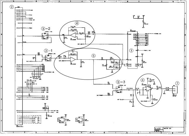
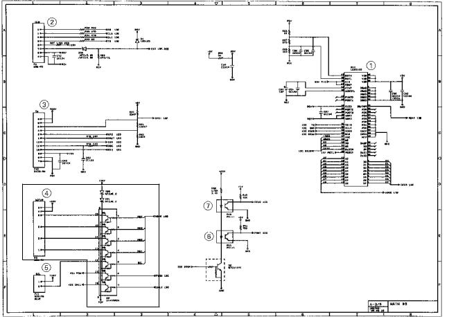
[ 4 ] Analog signal processing group
Main PCB Circuit Diagram 4/4
1 Analog front end IC
Processes the analog I/O signals from/to the MODEM.
2 Main-NCU connector
3 Analog signal selectors
3-1: Selects either RL1 or RL2 signals inputted from the communications network.
3-2: Selects either input signals from the handset or those from the MODEM.
3-3: Selects either sound signals (e.g. alarm beeps, key clicks and ringer sounds) generated by the FAX engine or signals selected by 3-1.
4 Amplifier circuit for signals outputted from the MODEM
5 Amplifier & shaper circuit for signals inputted from the communications network
6Speaker amplifier circuit
Amplifies sounds issued from the above analog signal selector (3) and feeds them to the speaker.
7 Speaker connector
III –15
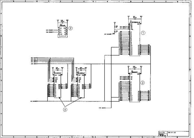
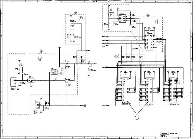
3.2.2FAX725M/590DT/590MC/825MC/875MC
[ 1 ] Primary function group
Main PCB Circuit Diagram 1/5
1 FAX engine (ASIC) which integrates a CPU and gate array.
2 Clock for CPU
3 Clock for calendar clock
4 ROM (2-megabit. Note that the sample machines for demonstration have a 4- megabit ROM.)
5 E2PROM (16-kilobit in the FAX725M/590DT/590MC/825MC, 32-kilobit in the
FAX875MC)
6 Control panel connector
7 LED array light intensity control circuit and connector
8 Recording head drive voltage detector
III –16
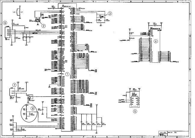
[ 2 ] DRAM group
Main PCB Circuit Diagram 2/5
1 DRAMs
FAX725M: |
Two 256-kilobyte DRAMs |
FAX590DT/590MC/825MC/875MC: Two 512-kilobyte DRAMs
2 Calendar clock backup circuit (for the FAX725M)
3DRAM backup circuit and nickel-hydrogen battery connector (for the FAX590DT/ 590MC/825MC/875MC)
4 DRAM refresh circuit (for the FAX590DT/590MC/825MC/875MC)
5 Reset IC
III –17
 Loading...