


 Loading...
BAS-311F-0, 311F-L INSTRUCTION MANUAL
BAS-326F-0
Please read this manual before using the machine.
Please keep this manual within easy reach for quick reference.
PROGRAMMABLE ELECTRONIC PATTERN SEWER
Thank you very much for buying a BROTHER sewing machine. Before using your new machine, please read the safety instructions below and the explanations given in the instruction manual.
With industrial sewing machines, it is normal to carry out work while positioned directly in front of moving parts such as the needle and thread take-up lever, and consequently there is always a danger of injury that can be caused by these parts. Follow the instructions from training personnel and instructors regarding safe and correct operation before operating the machine so that you will know how to use it correctly.
SAFETY INSTRUCTIONS
1 Safety indications and their meanings
This instruction manual and the indications and symbols that are used on the machine itself are provided in order to ensure safe operation of this machine and to prevent accidents and injury to yourself or other people. The meanings of these indications and symbols are given below.
Indications
DANGER The instructions which follow this term indicate situations where failure to follow the instructions will almost certainly result in death or severe injury.
The instructions which follow this term indicate situations where failure to follow the CAUTION instructions could cause injury when using the machine or physical damage to
equipment and surroundings.
Symbols
........................................ This symbol (  ) indicates something that you should be careful of. The picture inside the triangle indicates the nature of the caution that must be taken.
(For example, the symbol at left means “beware of injury”.)
........................................ This symbol ( |
) indicates something that you must not do. |
........................................ This symbol ( |
) indicates something that you must do. The picture |
inside the circle indicates the nature of the thing that must be done.
(For example, the symbol at left means “you must make the ground connection”.)
BAS-311F-0, 311F-L, 326F-0
i
2 Notes on safety
 DANGER
Wait at least 5 minutes after turning off the power switch and disconnecting the power cord from the wall outlet before opening the face plate of the control box. Touching areas where high voltages are present can result in severe injury.
 CAUTION
Environmental requirements
Use the sewing machine in an area which is free from sources of strong electrical noise such as high-frequency welders.
Sources of strong electrical noise may cause problems with correct operation.
Any fluctuations in the power supply voltage should be within  10% of the rated voltage for the machine.
Voltage fluctuations which are greater than this may cause problems with correct operation.
The power supply capacity should be greater than the requirements for the sewing machine’s electrical consumption.
Insufficient power supply capacity may cause problems with correct operation.
The pneumatic delivery capability should be greater than the requirements for the sewing machine's total air consumption.
Insufficient pneumatic delivery capability may cause problems with correct operation.
The ambient temperature should be within the
range of 5 to 35 during use.
Temperatures which are lower or higher than this may cause problems with correct operation.
The relative humidity should be within the range of 45% to 85% during use, and no dew formation should occur in any devices.
Excessively dry or humid environments and dew formation may cause problems with correct operation.
Avoid exposure to direct sunlight during use. Exposure to direct sunlight may cause problems with correct operation.
In the event of an electrical storm, turn off the power and disconnect the power cord from the wall outlet.
Lightning may cause problems with correct operation.
Installation
Machine installation should only be carried out by a qualified technician.
Contact your Brother dealer or a qualified electrician for any electrical work that may need to be done.
The sewing machine weighs more than 65 kg. (311F-0), 70 kg (311F-L, 326 F-0) The installation should be carried out by two or more people.
Do not connect the power cord until installation is complete, otherwise the machine may operate if the foot switch is depressed by mistake, which could result in injury.
Hold the machine head with both hands by two or more people when tilting it back or returning it to its original position.
Furthermore, after tilting back the machine head, do not push the face plate side or the pulley side from above, as this could cause the machine head to topple over, which may result in personal injury or damage to the machine.
Be sure to connect the ground. If the ground connection is not secure, you run a high risk of receiving a serious electric shock, and problems with correct operation may also occur.
All cords should be secured at least 25 mm away from any moving parts. Furthermore, do not excessively bend the cords or secure them too firmly with staples, otherwise there is the danger that fire or electric shocks could occur.
Install the belt cover and the frame side cover to the machine head and motor.
If using a work table which has casters, the casters should be secured in such a way so that they cannot move.
Be sure to wear protective goggles and gloves when handling the lubricating oil and grease, so that they do not get into your eyes or onto your skin, otherwise inflammation can result.
Furthermore, do not drink the oil or eat the grease under any circumstances, as they can cause vomiting and diarrhoea.
Keep the oil out of the reach of children.
BAS-311F-0, 311F-L, 326F-0
ii
 CAUTION
Sewing
This sewing machine should only be used by |
If using a work table which has casters, the casters |
|
operators who have received the necessary |
should be secured in such a way so that they |
|
training in safe use beforehand. |
cannot move. |
|
The sewing machine should not be used for any |
Attach all safety devices before using the sewing |
|
applications other than sewing. |
machine. If the machine is used without these |
|
Be sure to wear protective goggles when using the |
devices attached, injury may result. |
|
machine. |
Do not touch any of the moving parts or press any |
|
If goggles are not worn, there is the danger that if a |
objects against the machine while sewing, as this |
|
needle breaks, parts of the broken needle may |
may result in personal injury or damage to the |
|
enter your eyes and injury may result. |
machine. |
|
Set the needle to the needle up stop position |
If an error occurs in machine operation, or if abnormal |
|
before turning off the power. |
noises or smells are noticed, immediately turn off the |
|
If this is not done, the wiper may strike the needle, |
power switch. Then contact your nearest Brother |
|
which might cause the needle to break. |
dealer or a qualified technician. |
|
Turn off the power switch at the following times, |
If the machine develops a problem, contact your |
|
otherwise the machine may operate if the foot |
nearest Brother dealer or a qualified technician. |
|
switch is depressed by mistake, which could result |
|
|
in injury. |
|
|
When replacing bobbin |
|
|
When not using the machine and when leaving |
|
|
the machine unattended |
|
|
|
|
|
Cleaning |
|
|
Turn off the power switch before carrying out |
Be sure to wear protective goggles and gloves |
|
cleaning, otherwise the machine may operate if |
when handling the lubricating oil and grease, so |
|
the foot switch is depressed by mistake, which |
that they do not get into your eyes or onto your |
|
could result in injury. |
skin, otherwise inflammation can result. |
|
Wait until the motor has cooled down before |
Furthermore, do not drink the oil or eat the grease |
|
under any circumstances, as they can cause |
||
cleaning the air holes. |
||
vomiting and diarrhoea. |
||
The motor may be hot immediately after it has |
Keep the oil out of the reach of children. |
|
been used, and it may cause burns if touched. |
|
|
|
||
Maintenace and inspection |
||
Maintenance and inspection of the sewing |
If the power switch and air need to be left on when |
|
machine should only be carried out by a qualified |
carrying out some adjustment, be extremely |
|
technician. |
careful to observe all safety precautions. |
|
Ask your Brother dealer or a qualified electrician to |
Hold the machine head with both hands by two or |
|
carry out any maintenance and inspection of the |
more people when tilting it back or returning it to its |
|
electrical system. |
original position. |
|
Turn off the power switch and disconnect the |
Furthermore, after tilting back the machine head, |
|
power cord from the wall outlet at the following |
do not push the face plate side or the pulley side |
|
times, otherwise the machine may operate if the |
from above, as this could cause the machine head |
|
foot switch is depressed by mistake, which could |
to topple over, which may result in personal injury |
|
result in injury. |
or damage to the machine. |
|
When carrying out inspection, adjustment and |
Use only the proper replacement parts as |
|
maintenance |
||
specified by Brother. |
||
When replacing consumable parts such as the |
||
|
||
rotary hook |
If any safety devices have been removed, be |
|
Disconnect the air hoses from the air supply and |
absolutely sure to re-install them to their original |
|
positions and check that they operate correctly |
||
wait for the needle on the pressure gauge to drop |
||
before using the machine. |
||
to “0” before carrying out inspection, adjustment |
||
|
||
and repair of any parts which use the pneumatic |
Any problems in machine operation which result |
|
equipment. |
from unauthorized modifications to the machine |
|
will not be covered by the warranty.
BAS-311F-0, 311F-L, 326F-0
iii
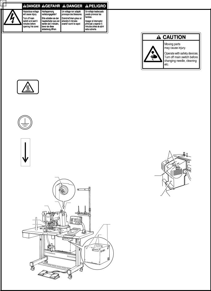
3 Warning labels
 The following warning labels appear on the sewing machine.
Please follow the instructions on the labels at all times when using the machine. If the labels have been removed or are difficult to read, please contact your nearest Brother dealer.
1 |
2 |
Safety devices
3 High temperature warning display Eye guard Finger guard
Thread take-up cover Belt cover
Frame side cover, etc.
4
Be sure to connect the ground. If the ground connection is not secure, you run a high risk of receiving a serious electric shock, and problems with correct operation may also occur.
5
Direction of operation
2
5 |
3 |
Frame side cover |
1156S |
Belt cover |
2 |
|
Thread take-up cover |
||
|
||
Eye guard |
|
|
Finger guard |
4 |
|
|
1 |
1293S
BAS-311F-0, 311F-L, 326F-0
iv
CONTENTS |
|
1. NAME OF MAJOR PARTS .......................................................................................................... |
1 |
2. SPECIFICATIONS ................................................................................................................................... |
2 |
3. INSTALLATION ........................................................................................................................................... |
3 |
3-1. Table processing diagram ............................................................................................................................................... |
4 |
3-2. Positioning .......................................................................................................................................................................... |
4 |
3-3. Installing the control box .................................................................................................................................................. |
5 |
3-4. Installing the rubber cushions ........................................................................................................................................ |
6 |
3-5. Installing the oil pan .......................................................................................................................................................... |
6 |
3-6. Installing the cushions ...................................................................................................................................................... |
7 |
3-7. Installing the switching plate ........................................................................................................................................... |
7 |
3-8. Installing the machine head ............................................................................................................................................ |
8 |
3-9. Tilting the sewing machine head ................................................................................................................................... |
9 |
3-10. Connecting the ground wire ....................................................................................................................................... |
11 |
3-11. Connecting the cords (Installing the operation panel) .......................................................................................... |
11 |
3-12. Installing the belt cover ................................................................................................................................................ |
14 |
3-13. Installing the foot switch ........................................................................................................................................... |
14 |
3-14. Installing the spool stand ............................................................................................................................................. |
14 |
3-15. Installing the eye guard ............................................................................................................................................... |
15 |
3-16. Installing the programmer (option) ............................................................................................................................ |
16 |
3-17. Installing the work clamp lifter connecting rod (BAS-311F-0 solenoid type only) .................................. |
16 |
3-18. Installing the feed base cover supports (BAS-311F-L, 326F-0) ......................................................................... |
17 |
3-19. Installing the X feed base cover (BAS-311F-L, 326F-0) ................................................................................... |
17 |
3-20. Connecting the tubes (pneumatic type only) .......................................................................................................... |
18 |
3-20-1. Installing the air unit................................................................................................................................................... |
19 |
3-20-2. Adjusting the speed controller ................................................................................................................................ |
19 |
4. LUBRICATION.............................................................................................................................................. |
20 |
5. CORRECT OPERATION................................................................................................................. |
21 |
5-1. Selecting the needle and thread .................................................................................................................................. |
21 |
5-2. Installing the needle ........................................................................................................................................................ |
21 |
5-3. Threading the upper thread .......................................................................................................................................... |
22 |
5-4. Winding the lower thread .............................................................................................................................................. |
23 |
5-5. Replacing the bobbin case and threading the thread ............................................................................................. |
24 |
5-6. Sewing conditions and thread tension ....................................................................................................................... |
24 |
5-6-1. Sewing conditions ..................................................................................................................................................... |
24 |
5-6-2. Lower thread tension ................................................................................................................................................ |
25 |
5-6-3. Upper thread tension ................................................................................................................................................ |
25 |
5-6-4. Thread take-up spring height ................................................................................................................................... |
25 |
5-6-5. Thread take-up spring tension .................................................................................................................................. |
25 |
5-6-6. Adjusting arm thread guide R.................................................................................................................................... |
25 |
6. USING THE OPERATION PANEL.................................................................................... |
26 |
6-1. Explanation of panel ....................................................................................................................................................... |
26 |
6-2. Using the floppy disk ...................................................................................................................................................... |
28 |
6-3. Using the program R/W (Read/Write) switch ........................................................................................................... |
30 |
6-4. Using the TEST switch (Checking the sewing pattern) .......................................................................................... |
31 |
6-5. Using the emergency stop switch ............................................................................................................................... |
32 |
6-6. Adjusting the sewing SPEED control ....................................................................................................................... |
33 |
6-7. Changing the X-SCALE and Y-SCALE settings ...................................................................................................... |
33 |
BAS-311F-0, 311F-L, 326F-0
6-8. Using the bobbin thread counter ................................................................................................................................. |
34 |
6-9. Using production counter .............................................................................................................................................. |
35 |
6-10. Using single split mode ............................................................................................................................................... |
36 |
6-11. Shifting a stitch pattern ................................................................................................................................................ |
37 |
7. SEWING ............................................................................................................................................................... |
38 |
7-1. Before starting sewing.................................................................................................................................................... |
38 |
7-2. Sewing operation ............................................................................................................................................................ |
38 |
8. CLEANING AND INSPECTION ......................................................................................... |
40 |
8-1. Cleaning the rotary hook ............................................................................................................................................... |
40 |
8-2. Lubrication ........................................................................................................................................................................ |
40 |
8-3. Draining the oil ................................................................................................................................................................ |
40 |
8-4. Cleaning the control box air inlet port ......................................................................................................................... |
41 |
8-5. Cleaning the air holes of belt cover and frame side cover .................................................................................... |
41 |
8-6. Cleaning the eye guard ................................................................................................................................................. |
41 |
8-7. Checking the needle ...................................................................................................................................................... |
41 |
9. STANDARD ADJUSTMENTS ............................................................................................... |
42 |
9-1. Adjusting the needle bar height.................................................................................................................................... |
42 |
9-2. Adjusting the needle bar lift amount ........................................................................................................................... |
42 |
9-3. Adjusting the needle clearance ................................................................................................................................... |
43 |
9-4. Adjusting the driver needle guard ............................................................................................................................... |
43 |
9-5. Adjusting the shuttle race thread guide ..................................................................................................................... |
43 |
9-6. Adjusting the movable knife ......................................................................................................................................... |
44 |
9-7. Adjusting the presser foot .............................................................................................................................................. |
46 |
9-8. Changing the presser foot lift ....................................................................................................................................... |
47 |
9-9. Adjusting the wiper ......................................................................................................................................................... |
48 |
9-10. Adjusting the two-step work clamp lift amount ....................................................................................................... |
49 |
9-10-1. BAS-311F-0 Solenoid type .................................................................................................................................... |
49 |
9-10-2. BAS-311F-0, 311F-L Pneumatic type .................................................................................................................... |
49 |
9-10-3. BAS-326F-0 ............................................................................................................................................................ |
50 |
9-10-4. Adjusting the air pressure ...................................................................................................................................... |
50 |
9-11. Adjusting the needle up stop position ...................................................................................................................... |
51 |
9-12. Checking the input sensor and DIP switch input ................................................................................................... |
52 |
9-13. Checking the input voltage ......................................................................................................................................... |
53 |
9-14. Clearing all memory settings ..................................................................................................................................... |
53 |
10. DIP SWITCH .............................................................................................................................................. |
54 |
10-1. Panel DIP switch functions ......................................................................................................................................... |
54 |
10-2. DIP swtiches inside the control box .......................................................................................................................... |
56 |
11. CHANGING SPECIAL FUNCTIONS AND |
|
USING THE MEMORY SWITCHES ........................................................................ |
58 |
12. ERROR CODES ..................................................................................................................................... |
63 |
13. GAUGE PARTS LIST ACCORDING TO SUBCLASSES ............. |
66 |
14. TROUBLESHOOTING ................................................................................................................. |
68 |
15. OPTIONS ........................................................................................................................................................ |
72 |
BAS-311F-0, 311F-L, 326F-0
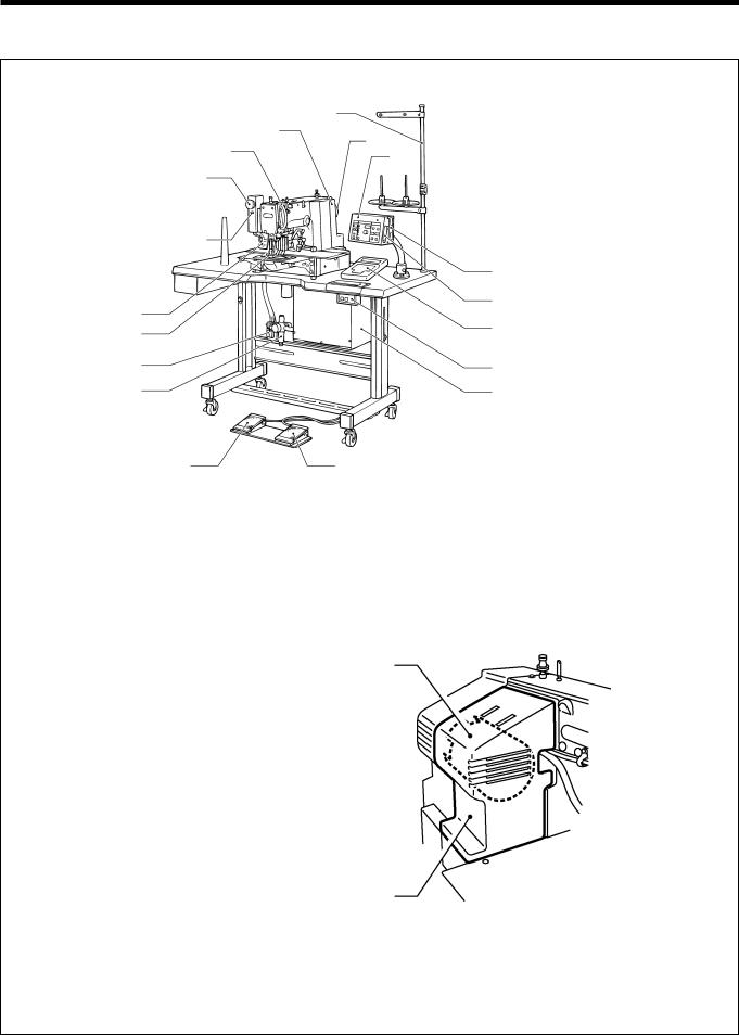
1. NAME OF MAJOR PARTS
1. NAME OF MAJOR PARTS
|
(12) |
(8) |
|
(11) |
(7) |
||
|
|||
|
(3) |
||
|
|
(16)
(17)
(10)
(9)
(20)
(19)
(4) |
(5) |
1157S
(1)Power switch
(2)Control box
(3)Operation panel
(4)Presser lifter pedal
(5) Starting pedal |
(6) |
(6)Motor cover
(7)Pulley
(8)Spool stand
(14)Programmer
(15)Floppy disk drive
(16)Emergency stop swich
(17)Thread wiper switch
(18)Dip switch
(19)Integrater
(20)Solenoid valve
Safety devices |
(13) |
|
(9)Finger guard
(10)Eye guard
(11)Thread take-up cover
(12)Belt cover
(13)Frame side cover
(15)
(18)
(14)
(1)
(2)
1159S
BAS-311F-0, 311F-L, 326F-0
1

2. SPECIFICATIONS
2. SPECIFICATIONS
|
*1 |
*2 |
|
BAS-311F-0 [*1] [*2] |
1. For Heavy-weight Materials |
|
S. Work Clamp Lifter (Solenoid Type) |
|
2. For Medium-weight Materials |
|
A. Work Clamp Lifter (Pneumatic Type) |
|
3. For Extra heavy-weight Materials |
|
|
|
|
|
|
|
4. For special use |
|
|
|
|
|
|
BAS-311F-L [*3] A
BAS-326F-0 [*4] A
*3
1. For Heavy-weight materials, Work Clamp Lifter (Pneumatic Type) 4. For special use, Work clamp Lifter (Pneumatic Type)
*4
1.For Heavy-weight Materials, Work Clamp Lifter (Pneumatic Type)
2.For Medium-weight Materials, Work Clamp Lifter (Pneumatic Type)
4.For special use, Work Clamp Lifter (Pneumatic Type)
Stitch formation |
Single needle lock stitch |
|
|
|
|
Sewing machine |
Lock stitch, pattern tacking sewing machine (with large shuttle hook) |
|
|
|
|
Maximum pattern size |
BAS-311F-0: 130 X 60 mm, BAS-311F-L: 220 X 60 mm, BAS-326F-0: 220 X 100 mm |
|
|
|
|
Maximum stitch number |
20,000 (one pattern) |
|
|
|
|
Stitch length |
0.05 - 12.7 mm |
|
|
|
|
Maximum sewing speed |
2,500 rpm (When stitch length is 3 mm or less) |
|
|
|
|
Feed mechanism |
Intermittent feed, pulse motor drive |
|
|
|
|
Rotary hook |
Shuttle hook (Standard rotary hook is sold separately) |
|
|
|
|
Needle |
DP X 5, DP X 17, MR |
|
|
|
|
Data storage method |
3.5 floppy disk 2HD/1.44MB, 2DD |
|
|
|
|
Test function |
Operation test function provided for use with low speed drive |
|
|
|
|
Safety devices |
Automatic stop function for activation in the event of misoperation realized with intermediate |
|
stop function and safety circuits |
||
|
||
|
|
|
Work clamp height |
BAS-311F-0:For solenoid - Max. 25 mm, for pneumatic - Max. 30 mm |
|
BAS-311F-L, BAS-326F-0:Max. 30 mm |
||
|
||
|
|
|
2-step work clamp |
BAS-311F-0:For solenoid - unit work clamp, for pneumatic - separate work clamp |
|
BAS-311F-L, BAS-326F-0:Separate work clamp |
||
|
||
|
|
|
Work clamp lift stroke |
18 mm |
|
|
|
|
Intermittent stroke |
0 or 3 (Factory default) - 8 mm |
|
|
|
|
Weights |
Machine head BAS-311F-0: 65kg, BAS-311F-L, BAS-326F-0: 70kg |
|
Control box: 10 - 20 kg (depending on destination) |
||
|
||
|
|
|
Power supply |
Single-phase 110V, 220V, 240V, 3-phase 220V, 380V, 400V, 600VA |
|
|
|
|
Motor |
Three-phase 400 W induction motor |
|
|
|
|
Air pressure |
0.50 MPa 1.8 l/ min |
|
|
|
|
Power table |
T-shaped for use sitting or standing |
|
|
|
|
Machine dimensions |
1,200W X 590 D X 1,120 H mm (Sitting) |
|
1,350 H mm (Standing) …..Excluding spool stand |
||
|
||
|
|
BAS-311F-0, 311F-L, 326F-0
2

|
|
|
|
|
|
|
|
|
3. INSTALLATION |
|
|
|
|
|
|
|
|||||
|
|
|
|
|
|
|||||
|
3. INSTALLATION |
|
|
|
|
|||||
|
|
|
|
|
|
|
|
CAUTION |
|
|
|
Machine installation should only be carried out by |
All cords should be secured at least 25 mm away |
|
|||||||
|
a qualified technician. |
|
|
|
|
from any moving parts. Furthermore, do not |
|
|||
|
Contact |
your |
Brother |
dealer |
or |
a qualified |
excessively bend the cable or secure it too firmly |
|
||
|
staples, otherwise there is the danger that fire or |
|
||||||||
|
electrician for any electrical work that may need to |
|
||||||||
|
electric shocks could occur. |
|
||||||||
|
be done. |
|
|
|
|
|
|
|
|
|
|
|
|
|
|
|
|
|
Install the belt cover and the frame side cover to |
|
|
|
The sewing machine head weighs more than 65 kg |
|
||||||||
|
the machine head and motor. |
|
||||||||
|
(311F-0), 70 kg (311F-L, 326F-0). The installation |
|
||||||||
|
|
|
||||||||
|
should be carried out by two or more people. |
|
If using a work table which has casters, the casters |
|
||||||
|
Do not connect the power cord until installation is |
should be secured in such a way so that they |
|
|||||||
|
cannot move. |
|
||||||||
|
complete, otherwise the machine may operate if |
|
||||||||
|
|
|
||||||||
|
the foot switch is depressed by mistake, which |
Be sure to wear protective goggles and gloves |
|
|||||||
|
could result in injury. |
|
|
|
|
when handling the lubricating oil and grease, so |
|
|||
|
Be sure |
to |
connect the |
ground. If |
the |
ground |
that they do not get into your eyes or onto your |
|
||
|
skin, otherwise inflammation can result. |
|
||||||||
|
connection |
is |
not secure, you |
run |
the |
risk of |
|
|||
|
Furthermore, do not drink the oil or eat the grease |
|
||||||||
|
receiving a serious electric shock. |
|
|
|
|
|||||
|
|
|
|
under any circumstances, as they can cause |
|
|||||
|
Hold the machine head with both hands by two or |
|
||||||||
|
vomiting and diarrhoea. |
|
||||||||
|
more peple when tilting it back or returning it to its |
keep the oil out of the reach of children. |
|
|||||||
|
original position. Furthermore, after tilting back the |
|
|
|||||||
|
machine head, do not push the face plate side or |
|
|
|||||||
|
the pulley side from above, as this could cause the |
|
|
|||||||
|
machine head to topple over, which may result in |
|
|
|||||||
|
personal injury or damage to the machine. |
|
|
|
||||||
|
|
|
|
|
|
|
|
|
|
|
BAS-311F-0, 311F-L, 326F-0
3

3. INSTALLATION
3-1. Table processing diagram
* If using a commercially-available table, process it as shown in the illustration below.
Note
The thickness of the table should be at least 40 mm, and it should be strong enough to bear the weight and vibration of the sewing machine.
If the distance A between the insides of the legs is less than 740 mm, move the control box installation position to the left (B=192 mm).
Check that the control box is at least 10 mm away from the leg. If the control box and leg are touching, it could cause the sewing machine to operate incorrectly.
[Standard]
1290S
3-2. Positioning
Determine the position for the sewing machine, and then lock the casters (1) so that the sewing machine will not move.
(1)
1161S
BAS-311F-0, 311F-L, 326F-0
4
3. INSTALLATION
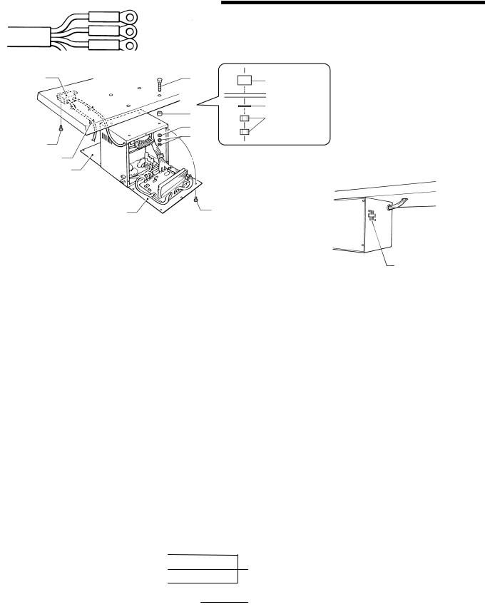
3-3. Installing the control box
(8) |
(4) |
(5) Spacer |
|
(5) |
(6) Flat washer |
|
(7) Nut |
|
|
(6) |
|
|
|
|
(9) |
(7) |
|
|
|
|
(10) |
|
|
(2) |
|
|
(3) |
|
(1) |
|
|
(11) |
1291S |
|
1292S |
|
|
|
1.Remove the screws (1), and then open the covers (panel mounting assembly (2) and main P.C. board mounting plate (3)).
Caution: When opening the cover, hold it securely so that it does not fall down.
2.Install the control box with the four accessory bolts (4), spacers (5), flat washers (6) and nuts (7) as shown in the illustration above.
*At this time, leave a gap of approximately 1 mm between the work table and the top of the box.
3.Close the covers (panel mounting assembly (2) and main P.C. board mounting plate (3)), and tighten them with the screws (1).
* The main P.C. board mounting plate (3) will be opened again during "3-11. Connecting the cords", so provisionally tighten it with the screw (1).
4.Install the power switch (8) with the two screws (9).
5.Secure the power switch cord with the five staples (10).
Note
 Secure the motor cord with staples in such a way that it does not cross over the outlet port of the cooling fan (11)
  Some specifications are not supplied with an accessory power switch (10). For these specifications, connect a power switch which satisfies the necessary regulations in the country of use.
Red
White
Black
Yellow/
Connect to the power switch. However,
the black wire is insulated to the inside of the box and is not used.
Connect to ground
0064Q
BAS-311F-0, 311F-L, 326F-0
5

3. INSTALLATION
3-4. Installing the rubber cushions
|
Install the rubber cushions (1) with the nails (2). |
|
|
|
* Install so that the head of the nail does not protrude |
(2) |
from the rubber surface. |
(1)
1296S
3-5. Installing the oil pan
0054Q
(1)
(2)
(3)
(2)
(4)
0055Q
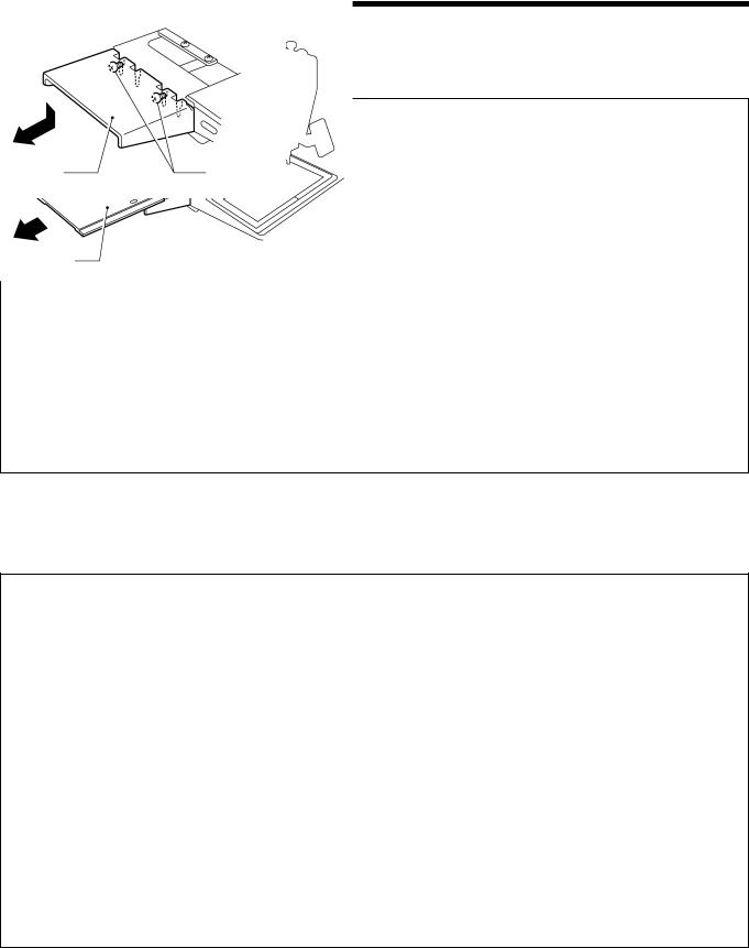
1.Insert the tabs of the oil pan (2) into the holes for the table (1), and then secure it in place with the five nails
(3) so that the oil pan (2) is not at an angle.
2.While pushing the oil pan (2) down from above, screw in the oil container (4).
BAS-311F-0, 311F-L, 326F-0
6
3. INSTALLATION
3-6. Installing the cushions
(2)
(1)
0056Q
Place the two cushions (1) into the holes in the work table, and secure them in place with the nails (2).
*Install so that the head of the nail does not protrude from the rubber surface.
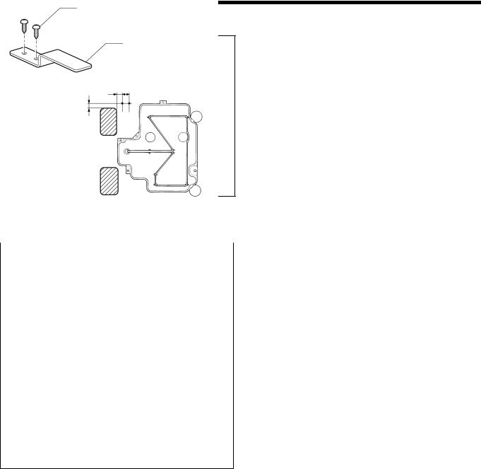
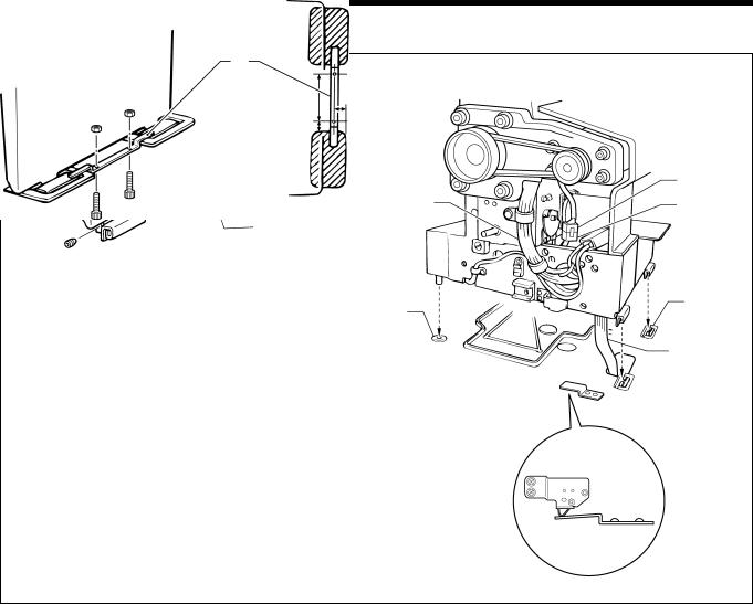
3-7. Installing the switching plate
(2) |
|
Install the switching plate (1) to the work table with the two |
|
wood screws (2) in the position shown in the illustration. |
|
|
|
* The switching plate and the switch bracket which is |
|
(1) |
attached to the machine head prevent the sewing |
|
machine from starting when the machine head is tilted |
|
|
|
|
|
|
back. Therefore, this means that the sewing machine |
|
|
will not start if the switching plate is not installed. |
|
15 |
|
11 |
9 |
|
|
|
1162S
BAS-311F-0, 311F-L, 326F-0
7
3. INSTALLATION
3-8. Installing the machine head
1163S
(2) |
|
(8) |
(5) |
(9) |
|
(1) |
|
|
(4) |
(3) |
|
|
||
|
|
(5) |
(6) |
|
|
|
|
|
133m |
14.5m |
|
|
|
|
13.2m |
|
|
|
|
Fig. 1 |
|
|
|
1164S |
1165S |
|
1.Insert the head hinges (1) into the machine head so that they are parallel, and then secure them with the two set screws (2).
2.Place the machine head gently on top of the rubber cushions (3) and cushions (4).
Note
Poll the cords (5) out as shown in the illustration above in order to prevent them from being clamped by the machine head.
3.Install the hinge presser (6) with the two bolts.
4.Check that the head position switch is turned on as shown in Figure 1.
5.Connect the motor cord connector (8) to the accessory cord connector (9).
BAS-311F-0, 311F-L, 326F-0
8
3. INSTALLATION
3-9. Tilting the sewing machine head
BAS-311F-L, 326F-0 : Remove the X feed base cover (1) and the feed base cover support (3) (below) from the machine head before tapping the head rest (5) (next page) into the work table.
BAS-311F-L BAS-326F-0
(2) |
(2) |
|
(1) |
(1) |
1166S |
1167S |
1. Loosen the screws (2) which are holding the X feed base cover L assembly (1) by about 2-3 turns, and then remove
the X feed base cover L assembly (1) in the direction of the arrow in the illustration.
Note
The sewing machine is packed without the X feed base cover L assembly (1) installed.
BAS-311F-L |
BAS-326F-0 |
|
|
|
|
|
(3) |
(4) |
|
(3) |
(4) |
|
|
|
||
|
|
|
|
|
|
|
|
|
|
1168S |
1169S |
2.Loosen the screws (4) which are holding the feed base cover support (3) on the left of the sewing machine (when looking from the front of the sewing machine) by about 2-3 turns, lift the feed base cover support (3) up slightly (BAS-
311F-L) or down slightly (BAS-326F-0), and then remove it in the direction of the arrow in the illustration.
Note
The sewing machine is packed without the feed base cover support (3) installed.
BAS-311F-0, 311F-L, 326F-0
9
3. INSTALLATION
BAS-311F-L |
BAS-326F-0 |
(4) |
(4) |
|
1170S |
1171S |
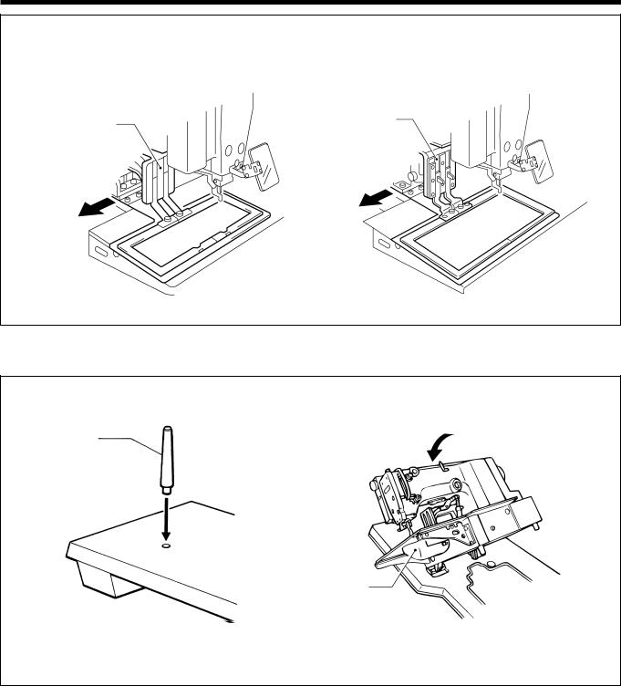
3.Move the presser arm assembly (4) as far as it will go in the direction of the arrow in the illustration (to the left when looking from the front of the sewing machine).
(5)
(6)
0060Q |
1172S |
4. Tap the head rest (5) into the table hole.
Note
Tap the head rest (5) securely into the work table as far as it will go.
5. Stand at the left side of the table, and gently tilt the machine towards you. When returning the machine to the original
position, be careful of the shuttle hook cover (6) and the cord.
Note
 Be sure to have two or more people there when tilting back the machine head and returning it to its original position.
 After tilting back the machine head, do not push the face plate or the pulley from above.
BAS-311F-0, 311F-L, 326F-0
10
3. INSTALLATION
3-10. Connecting the ground wire
 CAUTION
Be sure to connect the ground. If the ground connection is not secure, you run the risk of receiving a serious electric shock.
Connection method for 3-phase power supply
Red |
|
3- |
phase |
|
|
|
|||
White |
|
power supply |
||
|
||||
Black |
|
Yellow/Green |
||
Yellow/Green |
Connect to |
|||
|
|
|
|
ground |
|
|
|
|
0064Q |
3-11. Connecting the cords (Installing the operation panel)
(4)
(8) (3)
(1)
(9)
(2)
1 mm
40 mm
(7)
(6)
(5)
Front cover
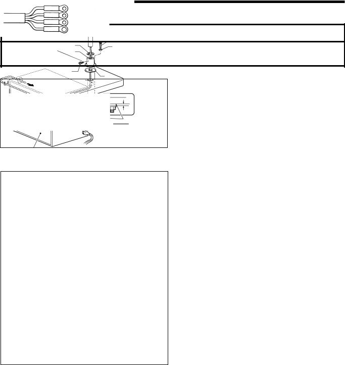
1.Assemble the operation panel stand (1) and cushion A
(2).Then insert the bolts (4) together with the washers
(3)into the three holes from above, and then tighten
the nuts (5), washers (6) and cushion B (7) from below
to secure the assembly.
Note
Tighten until the thickness of cushion B (7) becomes about 1 mm.
2.Pass the cords of the control panel assembly through the hole in the operation panel stand (1).
3.Attach the rubber sheet (8) to the hole in the operation panel stand (1) and then secure it with the bolt (9).
4.Insert the cord into the control box through the hole at the side of the box. Refer to page 13.
5.Secure the cord with the staples ( in two places).
Note
When opening the front cover, check that the code does not touch it.
1587Q
BAS-311F-0, 311F-L, 326F-0
11
3. INSTALLATION
|
|
|
|
|
|
|
|
|
|
|
|
|
|
|
|
|
|
|
|
|
|
|
|
|
|
|
|
|
|
|
|
|
|
|
(14) |
|
|
|
|
|
(10) |
|
(17) |
|
(15) |
|
|
|
|
|
|
|
|
|
|
|
(19) |
|
|
|
(11) |
|
|
|
|
|
|
(18) |
|
|
|
|
(16) |
|
|
|
|
|
|
|
(13) |
|
|
|
|
|
|
|
|
|
|
A |
|
|
|
|
|
||
|
|
|
|
|
|
|
|
|
|
1173S |
(12) |
|
|
1073Q |
|
|
|
|
1175S |
|
|
|
|
|
|
||||
|
|
|
|
|
|
|
|||
|
|
|
|
|
|
|
|
|
|
6. Gently tilt back the machine head. Refer to “3-9. Tilting the sewing machine head”.
Note
 Be sure to have two or more people there when tilting back the machine head and returning it to its original position.
 After tilting back the machine head, do not push the face side or the pulley side from above.
7. Pass the cords (10) through the hole (11) near the hinge of the work table.
Note
If the cords are passed through the wrong hole, they may become damaged.
8.Gently return the machine head to its original position.
9.Remove the screws (12), and then open the control box cover (main P.C. board mounting plate (13)).
Note
When opening the cover, hold it securely so that it dose not fall down.
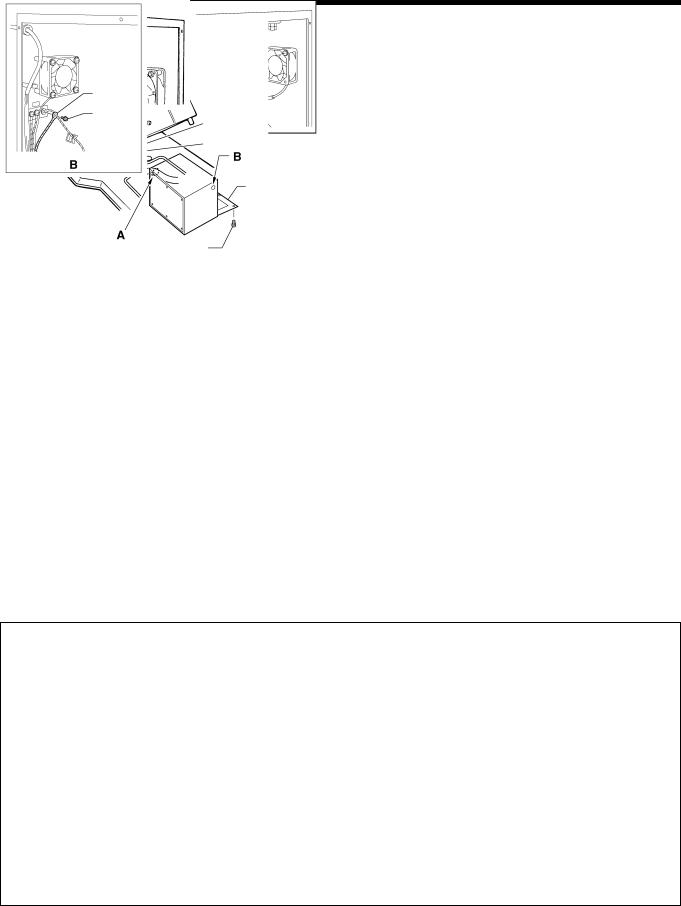
10.loosen the two screws (14), and then open the cord presser plate (15) in the direction of the white arrow and pass the cords (10) through the opening.
11.Loosen the screw (17), and then connect the ground wire (16) that is coming from the machine head as shown in the illustration.
12.Remove the screw (18), and then pass it through the terminal hole in the ground cord (19) from upper shaft motor. Then re-tighten the screw (18) so that the ground cord (19) is secured as shown in the illustration.
Note
Make sure that the ground connections are secure in order to ensure safety.
<BAS-311F-0 Solenoid type only>
(1)
(2)
(3) (1)
1424S
S1. Make hole in the beam as shown in the illustration above. (Button hole diameter is 4.2mm) S2. Install the ground wire (1) (accessory) to the beam with a tapping screw (2) (accessory).
S3. Loosen the screw (3), and then connect the ground wire (1) that is coming from the beam as shown in the illustration.
BAS-311F-0, 311F-L, 326F-0
12
3. INSTALLATION
(10)
(21)
(20)
Lock the cord clamp at the top.
(13) |
(12) |
1176S
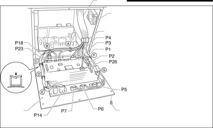
13. Securely connect connectors P1 to P7, P14, P18, P23 and P26 as indicated in table below.
Note
Check that the connector is facing the correct way, and then insert it firmly until it locks into place. Furthermore, lock the cord clamp at the top.
Machine head connectors |
|
Connection location on |
Cord clamps used |
|||
Connection location |
No. of pins |
Cord mark |
circuit board |
|||
|
||||||
X, Y, Sewing sensor |
12-pin |
[1] |
P1 |
(ORG) |
None |
|
Synchronizer |
5-pin |
[2] |
P2 |
(SYNCHRO) |
F |
|
EMERGENCY STOP switch |
9-pin |
[3] |
P3 |
(HEAD) |
None |
|
Solenoid valve |
12-pin |
[4] |
P4 |
(VALVE) |
None |
|
(for pneumatic) |
||||||
|
|
|
|
|
||
Solenoid |
|
|
|
|
F, G |
|
Presser foot |
8-pin |
[5] |
P5 |
(SOL) |
||
Thread trimmer |
|
|||||
|
|
|
|
|
||
Wiper |
|
|
|
|
|
|
Pulse motor, Y |
5-pin |
[6] |
P6 (YPM) |
F,G |
||
Pulse motor, X |
5-pin |
[7] |
P7 |
(XPM) |
F, G |
|
(blue) |
||||||
|
|
|
|
|
||
Upper shaft motor |
3-pin |
None |
P14 (UVM) |
A, B, C, D, E |
||
Operation panel |
10-pin |
[M] |
P18 (PANEL) |
A, B |
||
Head position switch |
3-pin |
[23] |
P23 (IMSW) |
A, B |
||
|
|
|
|
|
|
|
Machine specification select |
10-pin |
[26] |
P26 (SELECT) |
None |
||
connector |
||||||
|
|
|
|
|
||
14. Secure the cord bundle (10) with the cord clamp (20).
Note
Check that the cords do not get pulled when the machine head is tilted back gently.
15.Close the cord presser plate (15) in the direction of the black arrow, and secure it by tightening the screws (14).
16.Install the control box cover (main P.C. board mounting plate (13)) with the six screws (12).
Note
Check that the cords do not come into contact with the fan (21) and that they are not clamped by the cover at this time.
BAS-311F-0, 311F-L, 326F-0
13
3. INSTALLATION
3-12. Installing the belt cover
|
|
1. |
Loosen the two screws (2) of the upper cover (1). |
|
|
||
|
2. |
Insert the belt cover (3) in the direction of the arrow, |
|
(2) |
|
|
and then secure it with the two screws (2) and the two |
|
(1) |
|
screws (4). |
|
|
* it is not necessary to remove the belt cover (3) |
|
|
|
|
|
|
|
|
when tilting back the machine head. |
(3) |
|
|
|
(4) |
1177S |
|
3-13. Installing the foot switch
Insert the connector of the foot switch (2) into the connector (3) of the control box (1).
(1)
(3)
(2)
1178S
3-14. Installing the spool stand
Install the spool stand (1) to the table.
(1)
0073Q
BAS-311F-0, 311F-L, 326F-0
14
3. INSTALLATION
3-15. Installing the eye guard
 CAUTION
Attach all safety devices before using the sewing machine.
If the machine is used without these devices attached, injury may result.
Install the eye guard assy (1) to the face plate with the two screws (2).
(1)
(2) |
1180S |
BAS-311F-0, 311F-L, 326F-0
15
3. INSTALLATION
3-16. Installing the programmer (option)
|
[Vertical] |
|
[Flat] |
|
|
|
|
|
|
|
|
|
|
|
|
|
|
|
(2) |
|
(1) |
|
|
|
|
|
|
|
|
|
(1) |
|
|
|
|
|
|
|
(2) |
|
|
|
|
|
|
(4) |
(3) |
|
|
|
|||
1181S |
|
1182S |
1183S |
||
|
|
|
|
|
|
1.Install the programmer support (2) to the work table with the two screws (1).
2.Insert the programmer connector (4) securely into the left side of the operation panel (3).
3-17. Installing the work clamp lifter connecting rod (BAS-311F-0 solenoid type only)
(3)(5)
(7)
(1) |
(5) |
|
|
(3) |
|
(4) |
|
(6) |
(2) |
(8) |
1184S |
1185S |
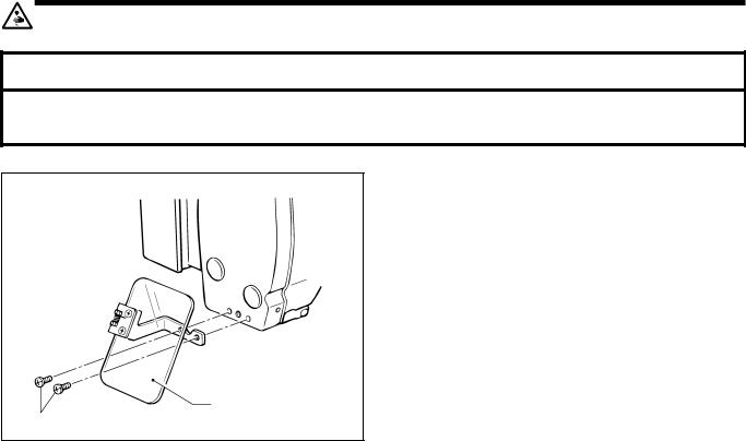
1.Remove the four screws (1), and then remove the side cover (2).
2.Install the work clamp lifter connecting rod (4) to the screw (3) on the work clamp lifter lever (5).
3.After installing, re-install the side cover (2) with the four screws (1).
Note
 Remove chain hooking back (7) which is attached to the work clamp lifter pedal (6) before tilting back the machine head.
 Move the treadle support base (8) back and forth to adjust so that the chain which is attached to the presser lifter connecting rod (4) and the presser lifter treadle (6) does not touch the cables.
BAS-311F-0, 311F-L, 326F-0
16
3. INSTALLATION
3-18. Installing the feed base cover supports (BAS-311F-L, 326F-0)
BAS-311F-L |
BAS-326F-0 |
|
|
|
|
Coinside |
Coinside |
|
|
|
|
|
Coinside |
(3) |
|
(2) |
(2) |
(1) |
(2) |
(1) |
|
|
||
1168S |
|
1169S |
1186S |
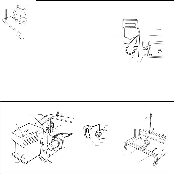
Loosen the four screws (1) on the side of the bed by about 2-3 turns, and then install the feed base cover supports (2) to the side of the bed so that the top surfaces of the feed base cover supports (2) (one each at left and right) are at the same height as the top surfaces of the X and Y feed base covers (3) (at left and right).
3-19. Installing the X feed base cover (BAS-311F-L, 326F-0)
1166S |
|
1167S |
BAS-311F-L |
|
BAS-326F-0 |
|
(1) |
(2) |
|
|
(1)
(2)
(2) |
(3) |
A |
(3) |
(4)
1187S
BAS-311F-L
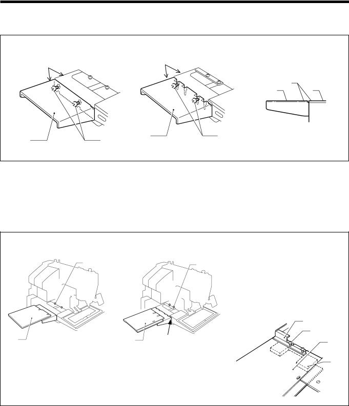
Loosen the four screws (1) by about 2-3 turns, slide the X feed base cover (2) (one each at left and right) in the direction of the arrow in the illustration, and then tighten the screws (1).
BAS-326F-0
1.Loosen the four screws (2) which are holding the bellows (1) by about 2-3 turns, and then slide the X feed base cover assemblies (3) (one each at left and right) in the direction of the arrow in the illustration into the gaps (section A) between the needle plate support plate and the X and Y feed base cover (at left and right).
2.Lift the bellows (1) up slightly, clamp the tops and bottoms of the X feed base cover assemblies (3) (one each at left and right) between the bellows (1) and the X feed base (4) and the then tighten the screws (2).
BAS-311F-0, 311F-L, 326F-0
17
3. INSTALLATION
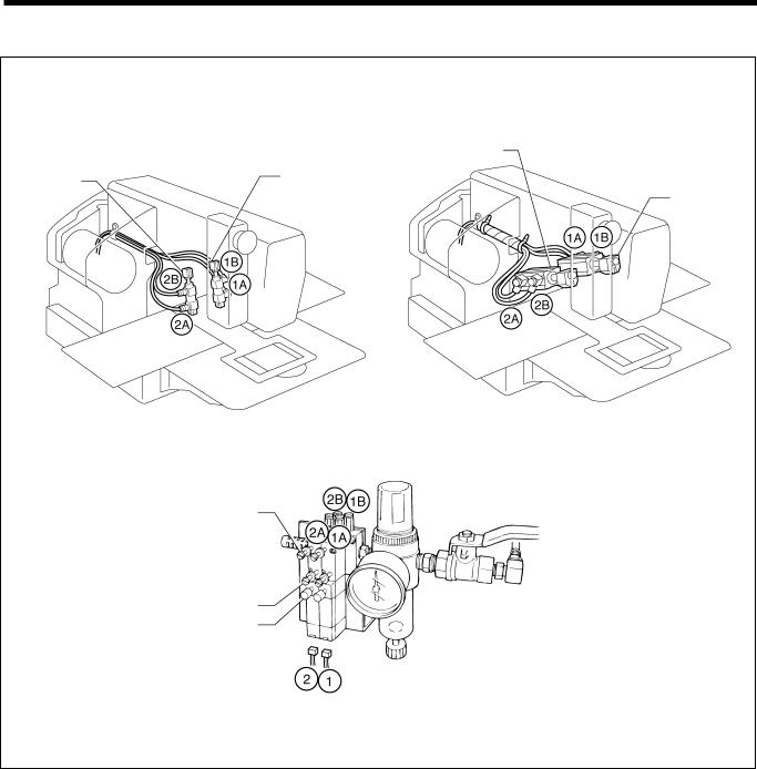
3-20. Connecting the tubes (pneumatic type only)
1188S |
1189S |
BAS-311F-0, 311F-L |
BAS-326F-0 |
|
Cylinder L |
Cylinder L |
Cylinder R |
|
Cylinder R |
Upper knob
Lower knob
Manual button
0319Q
Connect each air tube to the position with the corresponding number.
BAS-311F-0, 311F-L, 326F-0
18
Loading...