


 Loading...
INSTRUCTION MANUAL
BAS-341F
BAS-342F
Please read this manual before making using the machine.
Please keep this manual within easy reach for quick reference.
PROGRAMMABLE ELECTRONIC PATTERN SEWER

Thank you very much for buying a BROTHER sewing machine. Before using your new machine, please read the safety instructions below and the explanations given in the instruction manual.
With industrial sewing machines, it is normal to carry out work while positioned directly in front of moving parts such as the needle and thread take-up lever, and consequently there is always a danger of injury that can be caused by these parts. Follow the instructions from training personnel and instructors regarding safe and correct operation before operating the machine so that you will know how to use it correctly.
SAFETY INSTRUCTIONS
1 Safety indications and their meanings
This instruction manual and the indications and symbols that are used on the machine itself are provided in order to ensure safe operation of this machine and to prevent accidents and injury to yourself or other people. The meanings of these indications and symbols are given below.
Indications
D A N G E R The instructions which follow this term indicate situations where failure to follow the instructions will almost certainly result in death or severe injury.
The instructions which follow this term indicate situations where failure to follow the CAUTION instructions could cause injury when using the machine or physical damage to
equipment and surroundings.
Symbols
........................................This symbol (  ) indicates something that you should be careful of. The picture inside the triangle indicates the nature of the caution that must be taken.
(For example, the symbol at left means “beware of injury”.)
........................................This symbol ( |
) indicates something that you must not do. |
........................................This symbol ( |
) indicates something that you must do. The picture |
inside the circle indicates the nature of the thing that must be done.
(For example, the symbol at left means “you must make the ground connection”.)
i |
BAS-341F, 342F |

2 Notes on safety
 DANGER
Wait at least 5 minutes after turning off the power switch and disconnecting the power cord from the wall outlet before opening the face plate of the control box. Touching areas where high voltages are present can result in severe injury.
 CAUTION
Environmental requirements
Use the sewing machine in an area which is free from sources of strong electrical noise such as high-frequency welders.
Sources of strong electrical noise may cause problems with correct operation.
Any fluctuations in the power supply voltage should be within  10% of the rated voltage for the machine.
Voltage fluctuations which are greater than this may cause problems with correct operation.
The power supply capacity should be greater than the requirements for the sewing machine’s electrical consumption.
Insufficient power supply capacity may cause problems with correct operation.
The pneumatic delivery capability should be greater than the requirements for the sewing machine's total air consumption.
Insufficient pneumatic delivery capability may cause problems with correct operation.
The ambient temperature should be within the
range of 5 to 35 during use.
Temperatures which are lower or higher than this may cause problems with correct operation.
The relative humidity should be within the range of 45% to 85% during use, and no dew formation should occur in any devices.
Excessively dry or humid environments and dew formation may cause problems with correct operation.
Avoid exposure to direct sunlight during use. Exposure to direct sunlight may cause problems with correct operation.
In the event of an electrical storm, turn off the power and disconnect the power cord from the wall outlet.
Lightning may cause problems with correct operation.
Installation
Machine installation should only be carried out by a qualified technician.
Contact your Brother dealer or a qualified electrician for any electrical work that may need to be done.
The sewing machine weighs more than 200 kg. The installation should be carried out by two or more people.
Do not connect the power cord until installation is complete, otherwise the machine may operate if the foot switch is depressed by mistake, which could result in injury.
Hold the machine head with both hands by two or more people when tilting it back or returning it to its original position.
Furthermore, after tilting back the machine head, do not push the face plate side or the pulley side from above, as this could cause the machine head to topple over, which may result in personal injury or damage to the machine.
Be sure to connect the ground. If the ground connection is not secure, you run a high risk of receiving a serious electric shock, and problems with correct operation may also occur.
Install the belt cover and the frame side cover to the machine head and motor.
If using a work table which has casters, the casters should be secured in such a way so that they cannot move.
Be sure to wear protective goggles and gloves when handling the lubricating oil and grease, so that they do not get into your eyes or onto your skin, otherwise inflammation can result.
Furthermore, do not drink the oil or eat the grease under any circumstances, as they can cause vomiting and diarrhoea.
Keep the oil out of the reach of children.
BAS-341F, 342F |
ii |

 CAUTION
Sewing
This sewing machine should only be used by |
If using a work table which has casters, the |
|
operators who have received the necessary |
casters should be secured in such a way so that |
|
training in safe use beforehand. |
they cannot move. |
|
The sewing machine should not be used for any |
Attach all safety devices before using the sewing |
|
applications other than sewing. |
machine. If the machine is used without these |
|
Be sure to wear protective goggles when using the |
devices attached, injury may result. |
|
machine. |
Do not touch any of the moving parts or press any |
|
If goggles are not worn, there is the danger that if |
objects against the machine while sewing, as this |
|
a needle breaks, parts of the broken needle may |
may result in personal injury or damage to the |
|
enter your eyes and injury may result. |
machine. |
|
Set the needle to the needle up stop position |
If an error occurs in machine operation, or if abnormal |
|
before turning off the power. |
noises or smells are noticed, immediately turn off the |
|
If this is not done, the wiper may strike the needle, |
power switch. Then contact your nearest Brother |
|
which might cause the needle to break. |
dealer or a qualified technician. |
|
Turn off the power switch at the following times, |
If the machine develops a problem, contact your |
|
otherwise the machine may operate if the foot |
nearest Brother dealer or a qualified technician. |
|
switch is depressed by mistake, which could result |
|
|
in injury. |
|
|
• When replacing bobbin |
|
|
• When not using the machine and when leaving |
|
|
the machine unattended |
|
|
|
|
|
Cleaning |
|
|
Turn off the power switch before carrying out |
Be sure to wear protective goggles and gloves |
|
cleaning, otherwise the machine may operate if |
when handling the lubricating oil and grease, so |
|
the foot switch is depressed by mistake, which |
that they do not get into your eyes or onto your |
|
could result in injury. |
skin, otherwise inflammation can result. |
|
|
Furthermore, do not drink the oil or eat the grease |
|
|
under any circumstances, as they can cause |
|
|
vomiting and diarrhoea. |
|
|
Keep the oil out of the reach of children. |
|
Maintenance and inspection |
||
Maintenance and inspection of the sewing |
If the power switch and air need to be left on when |
|
machine should only be carried out by a qualified |
carrying out some adjustment, be extremely |
|
technician. |
careful to observe all safety precautions. |
|
Ask your Brother dealer or a qualified electrician to |
Hold the machine head with both hands by two or |
|
carry out any maintenance and inspection of the |
more people when tilting it back or returning it to its |
|
electrical system. |
original position. |
|
Turn off the power switch and disconnect the |
Furthermore, after tilting back the machine head, |
|
power cord from the wall outlet at the following |
do not push the face plate side or the pulley side |
|
times, otherwise the machine may operate if the |
from above, as this could cause the machine head |
|
foot switch is depressed by mistake, which could |
to topple over, which may result in personal injury |
|
result in injury. |
or damage to the machine. |
|
• When carrying out inspection, adjustment and |
Use only the proper replacement parts as |
|
maintenance |
||
specified by Brother. |
||
• When replacing consumable parts such as the |
||
|
||
rotary hook |
If any safety devices have been removed, be |
|
Disconnect the air hoses from the air supply and |
absolutely sure to re-install them to their original |
|
positions and check that they operate correctly |
||
wait for the needle on the pressure gauge to drop |
||
before using the machine. |
||
to “0” before carrying out inspection, adjustment |
||
|
||
and repair of any parts which use the pneumatic |
Any problems in machine operation which result |
|
equipment. |
from unauthorized modifications to the machine |
|
will not be covered by the warranty.
iii |
BAS-341F, 342F |

3 Warning labels
 The following warning labels appear on the sewing machine.
Please follow the instructions on the labels at all times when using the machine. If the labels have been removed or are difficult to read, please contact your nearest Brother dealer.
1 |
2 |
Safety devices
Eye guard
Finger guard
Thread take-up cover
Belt cover , etc.
3Be sure to connect the ground. If the ground connection is not secure, you run a high risk of receiving a serious electric shock, and problems with correct operation may also occur.
Thread take-up cover
Belt cover
Eye guard
Finger guard
1971S
BAS-341F, 342F |
iv |
CONTENTS |
|
1. NAME OF MAJOR PARTS .................................................................................................................... |
1 |
2. SPECIFICATIONS ........................................................................................................................................... |
2 |
3. PREPARATION .................................................................................................................................................. |
3 |
3-1. Before setting up .............................................................................................................................................................. |
3 |
3-2. Positioning ......................................................................................................................................................................... |
4 |
3-3. Tilting the sewing machine head .................................................................................................................................. |
4 |
3-4. Connecting the ground wire ........................................................................................................................................... |
5 |
3-5. V-belt tension ..................................................................................................................................................................... |
5 |
3-6. Installing the foot switch ............................................................................................................................................... |
5 |
3-7. Installing the spool stand ................................................................................................................................................ |
6 |
3-8. Installing the programmer (option) ............................................................................................................................... |
6 |
3-9. Adjusting the air pressure ............................................................................................................................................... |
7 |
4. LUBRICATION...................................................................................................................................................... |
8 |
4-1. Lubrication points ............................................................................................................................................................. |
8 |
5. CORRECT USE................................................................................................................................................... |
9 |
5-1. Selecting the needle and thread ................................................................................................................... |
9 |
5-2. Installing the needle and urnning the sewing machine.................................................................................. |
9 |
5-3. Threading the upper thread ........................................................................................................................ |
10 |
5-4. Winding the lower thread ............................................................................................................................ |
11 |
5-5. Replacing the bobbin case and threading the thread ................................................................................. |
12 |
5-6. Sewing conditions and thread tension ........................................................................................................ |
12 |
5-6-1. Sewing conditions .................................................................................................................................................... |
12 |
5-6-2. Lower thread tension ............................................................................................................................................... |
13 |
5-6-3. Upper thread tension ............................................................................................................................................... |
13 |
5-6-4. Thread take-up spring height ................................................................................................................................... |
13 |
5-6-5. Thread take-up spring tension.................................................................................................................................. |
13 |
5-6-6. Pretension tension .................................................................................................................................................... |
14 |
6. USING THE OPERATION PANEL................................................................................................ |
15 |
6-1. Explanation of panel .................................................................................................................................................... |
15 |
6-2. Using the floppy disk ................................................................................................................................................... |
17 |
6-3. Using the program R/W (Read/Write) switch ............................................................................................................. |
19 |
6-4. Using the TEST switch (Checking the sewing pattern) ............................................................................................. |
20 |
6-5. Using the emergency stop switch ............................................................................................................................... |
21 |
6-6. Adjusting the sewing SPEED control ....................................................................................................................... |
22 |
6-7. Changing the X-SCALE and Y-SCALE settings ........................................................................................................ |
22 |
6-8. Using the bobbin thread counter ................................................................................................................................ |
23 |
6-9. Using production counter ............................................................................................................................................ |
24 |
6-10. Using single split mode ............................................................................................................................................. |
25 |
6-11. Shifting a stitch pattern .............................................................................................................................................. |
26 |
BAS-341F, 342F
7. SEWING .................................................................................................................................................................... |
27 |
7-1. Before starting sewing.................................................................................................................................................... |
27 |
7-2. Sewing operation ............................................................................................................................................................ |
27 |
8. MAINTENANCE AND INSPECTION ........................................................................................ |
29 |
8-1. Cleaning the shuttle hook ............................................................................................................................................. |
29 |
8-2. Lubrication ........................................................................................................................................................................ |
29 |
8-3. Draining the oil ................................................................................................................................................................ |
30 |
8-4. Cleaning the control box air inlet port ......................................................................................................................... |
30 |
8-5. Cleaning the eye guard ................................................................................................................................................. |
31 |
8-6. Checking the needle ...................................................................................................................................................... |
31 |
9. STANDARD ADJUSTMENTS .......................................................................................................... |
32 |
9-1. Adjusting the needle bar height.................................................................................................................................... |
32 |
9-2. Adjusting the needle bar lift amount ........................................................................................................................... |
32 |
9-3. Adjusting the needle clearance ................................................................................................................................... |
33 |
9-4. Adjusting the driver needle guard ............................................................................................................................... |
33 |
9-5. Adjusting the shuttle race thread guide ..................................................................................................................... |
33 |
9-6. Adjusting the movable knife ......................................................................................................................................... |
34 |
9-7. Adjusting the presser foot.............................................................................................................................................. |
36 |
9-8. Changing the presser foot lift ....................................................................................................................................... |
37 |
9-9. Adjusting the wiper.......................................................................................................................................................... |
38 |
9-10. Adjusting the needle up stop position ...................................................................................................................... |
38 |
9-11. Checking the input sensor and DIP switch input ................................................................................................... |
39 |
9-12. Checking the input voltage ......................................................................................................................................... |
40 |
9-13. Clearing all memory settings ..................................................................................................................................... |
40 |
10. DIP SWITCH ..................................................................................................................................................... |
41 |
10-1. Panel DIP switch functions ........................................................................................................................................ |
41 |
10-2. DIP switches inside the control box ......................................................................................................................... |
43 |
11. CHANGING SPECIAL FUNCTIONS AND |
|
USING THE MEMORY SWITCHES ........................................................................................ |
45 |
12. ERROR CODES ........................................................................................................................................... |
50 |
13. GAUGE PARTS LIST ACCORDING TO SUBCLASSES ............................... |
52 |
14. NOTES ON THE PROCESSING AND PRODUCTION |
|
OF PLATE BLANKS................................................................................................................................. |
53 |
15. TROUBLESHOOTING .......................................................................................................................... |
54 |
16. OPTIONS .............................................................................................................................................................. |
58 |
BAS-341F, 342F

1. NAME OF EACH PARTS
1.NAME OF EACH PARTS
■BAS-341F
Cotton stand
Emergency stop switch
Operation panel
Thread wiper switch
Programmer
|
Power switch |
Solenoid valve |
Control box |
Integrater |
|
Presser lifter pedal |
Starting pedal |
1917S
■ BAS-342F
Presser foot
Work clamp
Feed plate
1918S
BAS-341F, 342F
1
|
2. SPECIFICATIONS |
|
|
|
|
2. SPECIFICATIONS |
||
|
|
|
Stitch formation |
Single needle lock stitch |
|
|
|
|
Sewing machine |
Lock stitch, pattern tacking sewing machine (with large shuttle hook) |
|
|
|
|
Maximum pattern size |
BAS-341F: 250X 150 mm, BAS-342F: 300 X 200 mm |
|
|
|
|
Maximum stitch number |
20,000 (one pattern) |
|
|
|
|
Stitch length |
0.1 - 12.7 mm |
|
|
|
|
Maximum sewing speed |
2,500 rpm (When stitch length is 3 mm or less) |
|
|
|
|
Feed mechanism |
Intermittent feed, pulse motor drive |
|
|
|
|
Shuttle hook |
Double hook (Standard hook is sold separately) |
|
|
|
|
Needle |
DP X 5, DP X 17, MR |
|
|
|
|
Data storage method |
3.5 floppy disk 2HD/1.44MB, 2DD |
|
|
|
|
Test function |
Operation test function provided for use with low speed drive |
|
|
|
|
Safety devices |
Automatic stop function for activation in the event of misoperation realized with intermediate |
|
stop function and safety circuits |
||
|
||
|
|
|
Work clamp height |
Max.30 mm |
|
|
|
|
Work clamp |
Unit work clamp (special order-separate work clamp) |
|
|
|
|
Work clamp lift stroke |
18 mm |
|
|
|
|
Intermittent stroke |
0 or 3 (Factory default) - 8 mm |
|
|
|
|
Weights |
Machine head: 80kg, |
|
Control box: 10 - 20 kg (depending on destination) |
||
|
||
|
|
|
Power supply |
Single-phase 110V, 220V, 240V, 3-phase 220V, 380V, 400V, 900VA |
|
|
|
|
Motor |
Three-phase 400 W induction motor |
|
|
|
|
Air pressure |
0.50 MPa 1.8 l/ min |
|
|
|
|
Power table |
Use sitting or standing |
|
|
|
|
Machine dimensions |
BAS-341F 1,200W X 1,220D X 860H mm (Sitting)-1,130H mm (Standing) |
|
BAS-342F 1,200W X 1,270D X 860H mm (Sitting)-1,130H mm (Standing) |
||
|
||
|
|
|
BAS-341F, 342F
2

3. PREPARATION
3. PREPARATION
 CAUTION
Machine installation should only be carried out by |
Install the belt cover and the frame side cover to |
|
a qualified technician. |
the machine head and motor. |
|
Contact your Brother dealer or a qualified |
If using a work table which has casters, the |
|
electrician for any electrical work that may need to |
casters should be secured in such a way so that |
|
be done. |
they cannot move. |
|
The sewing machine head weighs more than 200 |
Be sure to wear protective goggles and gloves |
|
kg. The installation should be carried out by two or |
when handling the lubricating oil and grease, so |
|
more people. |
that they do not get into your eyes or onto your |
|
Do not connect the power cord until installation is |
skin, otherwise inflammation can result. |
|
Furthermore, do not drink the oil or eat the grease |
||
complete, otherwise the machine may operate if |
||
under any circumstances, as they can cause |
||
the foot switch is depressed by mistake, which |
||
vomiting and diarrhoea. |
||
could result in injury. |
||
keep the oil out of the reach of children. |
||
Be sure to connect the ground. If the ground |
||
|
||
connection is not secure, you run the risk of |
|
|
receiving a serious electric shock. |
|
|
Hold the machine head with both hands by two or |
|
|
more peple when tilting it back or returning it to its |
|
|
original position. Furthermore, after tilting back the |
|
|
machine head, do not push the face plate side or |
|
|
the pulley side from above, as this could cause the |
|
|
machine head to topple over, which may result in |
|
|
personal injury or damage to the machine. |
|
3-1. Before setting up
1. Install the Y driving shaft guard (1) to the rear of the arm with the bolt (2) and the spring washer (3).
2. Install the guard (4) to the table rear cover (5) with the bolt (6), spring washer (7), flat washer (8) and nut (9).
1919S
BAS-341F, 342F
3
3. PREPARATION
3-2. Positioning
Decide the position for the sewing machine. Loosen nuts of four level adjusters (1). Lower the level adjusters and secure them with nuts (2).
Turning the level adjuster counterclockwise will raise its height and turning it clockwise will lower it.
1920S
3-3. Tilting the sewing machine head
1921S
Gas spring
1922S
1.Remove screws (1) at the back of the work table, and remove table cover (rear) (2).
2. Remove bolt (3).
 The bolts are used to fix the machine in shipping. Generally they are needless after removing them keep them in another place.
3.Stand at the front of the table and slowly raise the machine (4). Then lock it.
4.When returning the machine to its former position, release lock (5). The gas spring will guide the machine to its original position.
BAS-341F, 342F
4

3. PREPARATION
3-4. Connecting the ground wire
 CAUTION
Be sure to connect the ground. If the ground connection is not secure, you run the risk of receiving a serious electric shock.
Connection method for 3-phase power supply.
Red |
|
3- |
phase |
|
|
|
|||
White |
|
power supply |
||
|
||||
Black |
|
Yellow/Green |
||
Yellow/Greeen |
Connect to |
|||
|
|
|
|
ground |
|
|
|
|
0064Q |
3-5. V-belt tension
These should approximately 10 - 12 mm of slack when V- belt is loaded at 9.8 N . To adjust, loosen the two nuts (1), and shift the motor up or down.
1923S
3-6. Installing the foot switch
Insert the connector of the foot switch (2) into the connector (3) of the control box (1).
1924S
BAS-341F, 342F
5

3. PREPARATION
3-7. Installing the spool stand
Install the spool stand (1) to the table.
(1)
|
|
|
|
|
|
0073Q |
|
|
|
|
||
|
|
|
|
|
|
|||||||
3-8. Installing the programmer (option) |
|
|
|
|
||||||||
|
|
|
|
|
|
|
|
|
|
|
|
|
|
|
[Vertical] |
|
|
|
[Flat] |
|
|
|
|
||
|
|
|
|
|
|
|
||||||
|
|
|
|
|
|
|
|
|
|
|
|
|
|
|
|
(2) |
|
|
(1) |
|
|
|
|
|
|
|
|
|
|
|
|
|
|
|
|
|
|
|
|
|
|
(1) |
|
|
(2) |
|
|
|
|
|
|
|
|
|
|
|
|
|
|
|
|
|
||
|
|
|
|
|
|
|
|
|
|
(4) |
(3) |
|
|
|
|
|
|
|
|
|
|
|
|
||
|
|
|
|
|
|
|
|
|
|
|
|
|
1181S |
|
|
|
1182S |
|
|
|
1183S |
||||
|
|
|
|
|||||||||
|
|
|
|
|
|
|
|
|
|
|
|
|
1.Install the programmer support (2) to the work table with the two screws (1).
2.Insert the programmer connector (4) securely into the left side of the operation panel (3).
BAS-341F, 342F
6

3. PREPARATION
3-9. Adjusting the air pressure
1. Air pressure should be 0.5 MPa.
The air pressure can be adjusted by pulling up and turning the control knob (2) on the integrator (1).
After adjustment is complete, push the control knob
(2) downward to lock it.
2. If water stands in the bottle of the integrator (1), turn the drain cock (3) in the direction indicated by an arrow to drain the water.
Note
Open the air cock (4) slowly.
1925S
BAS-341F, 342F
7

4. LUBRICATION
4. LUBRICATION
 CAUTION
Turn off the power switch before starting lubricating, otherwise the machine may operate if the foot switch is depressed by mistake, which could result in injury.
Be sure to wear protective goggles and gloves when handling the lubricating oil and grease, so that they do not get into your eyes or onto your skin, otherwise inflammation can result.
Furthermore, do not drink the oil or eat the grease under any circumstances, as they can cause vomiting and diarrhoea.
Keep the oil out of the reach of children.
Note
•Fill the machine with oil when the oil level is down to about one-third full in the oil sight glass.
If oil is not added and the oil drops below this level, there is the danger that the machine may seize during operation.
•Be sure to let the machine operate for a while after adding the oil.
•Use only specified Brother oil (Nisseki Mitsubishi Sewing Lube 10N; VG10) for the machine oil.
4-1. Lubrication points
|
|
|
1926S |
|
|
|
|
|
|
|
|
|
|
|
|
||
|
|
|
|
|
|
|
||
|
|
|
|
|
1927S |
|||
|
|
|
|
|
||||
|
|
|
|
|
|
|
|
|
1. Fill the arm-side oil tank with oil. |
2. Fill the bed-side oil tank with oil. |
|||||||
(Fill the oil tank with sewing machine oil.) |
|
|
|
|
||||
|
|
|
|
|
|
|
|
|
|
|
|
|
|
|
|
|
|
1928S |
1929S |
3. Add a drop of oil to the shuttle hook race.
4.If using the liquid cooling tank (1), fill it with silicon oil (100 mm2/S).
BAS-341F, 342F
8

5. CORRECT USE
5. CORRECT USE
5-1. Selecting the needle and thread
Needle |
Thread |
Main application |
|
|
|
|
|
DP X 5 |
#9 |
#100 - #60 |
Knitted wear |
|
|
|
|
DP X 5 #16 |
#80 - #50 |
General clothing |
|
|
|
|
|
DP X 17NY #19 |
#50 - #20 |
Denim |
|
|
|
|
|
DP X 17 |
#21 |
#50 - #20 |
Denim |
|
|
|
|
DP X 17 |
#25 |
#50 - #20 |
Leather•seat belts |
|
|
|
|
Different needles and threads are used for different sewing applications.
Refer to the table at left for details on which needle.
5-2. Installing the needle and running the sewing machine
 CAUTION
Turn off the power switch before installing the needle, otherwise the machine may operate of the foot switch is depressed by mistake and serious injury could result.
■ Installing the needle |
■ To turn the pulley by hand |
1930S
Loosen the set screw (1), insert the needle (2) as far as it will go so that the groove is facing toward you and then tighten the set screw (1).
Turning
Down
Press
1931S
Simply press in on the pulley (1) to turn it by hand. To turn the pulley, press lever (2) down.
•After turning the pulley by hand, be sure to press the lever down to return the pulley to the normal operating position.
BAS-341F, 342F
9
5. CORRECT USE
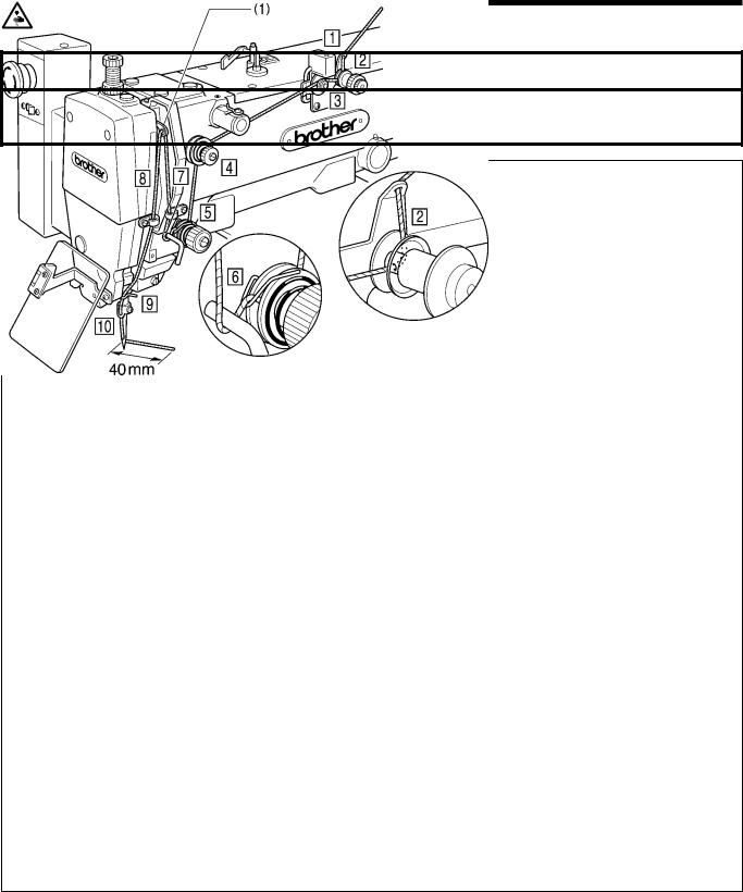
5-3. Threading the upper thread
 CAUTION
Turn off the power switch before threading the thread, otherwise the machine may operate of the foot switch is depressed by mistake and serious injury could result.
[When using cotton thread and spun yarn] |
1932S |
|
|
|
|
[With synthetic thread] |
[Threading in the upper thread breakage detector] |
||
|
|
|
|
|
|
|
|
|
|
|
|
|
|
|
|
Real the thread from above once or twice as the above figure.
1933S |
1934S |
■ Thread the upper thread correctly as shown in the illustration above.
Note
•Turn the machine pulley and raise the thread take-up lever (1) before threading the upper thread. (This will make threading easier and it will prevent the thread from coming out at the sewing start.)
•When threading the thread through the needle, allow a distance of approximately 40 mm between the needle hole
and the end of the thread. If the trailing length of the thread is too long, it may cause the thread to.
BAS-341F, 342F
10

5. CORRECT USE
5-4. Winding the lower thread
 CAUTION
Do not touch or place anything against any of the moving parts while winding the lower thread, otherwise personal injury or damage to the machine may result.
(1)
|
1198S |
|
|
|
|
1199S |
1935S |
|
(2) |
|
(5) |
|
(4) |
|
(1) |
0106Q |
0107Q |
|
|
|
|
(2) |
|
|
A |
(1)
B
0108Q
1.Place the bobbin all the way onto the shaft.
2.Thread the thread as shown in the illustration at left, wind the thread around the bobbin several times in the direction of the arrow, and then press the bobbin presser (1).
3.Turn on the power switch.
(The POWER indicator on the operation panel will illuminate.)
4.Check that the needle is not touching the presser foot, and then while pressing the STEP BACK switch (2), depress the foot switch (3) to start the machine. Keep depressing the foot switch (3) until the lower thread stops being wound onto the bobbin.
Release the STEP BACK switch (2) after the machine starts operating.
If you release the foot switch before winding is completed, depress it once more while pressing and holding the STEP BACK switch (2).
5.The bobbin presser (1) will automatically return to its original position after a set amount of thread (80 - 90% of the bobbin capacity) has been wound on.
6.Release the foot switch (3).
7.Remove the bobbin, hook the thread onto the knife (4), and then pull the bobbin in the direction of the arrow to cut the thread.
8.To wind more thread onto the bobbin, loosen the set screw (5) and pull the bobbin presser (1) outward.
<<If the thread winds onto the bobbin unevenly >>
If the thread winds onto the bobbin unevenly, loosen the nut (1) and turn the bobbin winder thread tension
stud (2) to adjust.
Note
If the thread winds on as shown in A, turn the bobbin winder thread tension stud (2) clockwise; if it winds on as shown in B, turn the bobbin winder thread tension stud (2) counterclockwise.
BAS-341F, 342F
11

5. CORRECT USE
5-5. Replacing the bobbin case and threading the thread
 CAUTION
If the power switch needs to be left on when carrying out replacing the bobbin, be extremely careful to observe all safety precautions.
The machine may operate if the foot switch is depressed by mistake, which could result in injury. (ex. Continuing sewing from a stopping point)
|
|
(2) |
|
|
|
|
|
|
|
|
|
|
(3) |
|
(4) |
30 mm |
|
|
|
|
|
|
|
|
|
|
|
|
|
|
|
|
|
|
|
1936S |
0110Q |
1202S |
1.Pull the shuttle race cover (1) forward and then open the cover.
2.Lift the bobbin case latch and remove the bobbin case.
3.Insert a new bobbin into the bobbin case, and then pass the thread through the slot (2) and pull it out from the thread hole (3). Check that the bobbin turns in the direction of the arrow when the thread is pulled at this time.
4.Pass the thread through the lever thread hole (4), and then pull out approximately 30 mm of thread.
5-6. Sewing conditions and thread tension
5-6-1. Sewing conditions
Specifications |
For heavy materials |
For medium materials |
|
|
|
Upper thread |
# 20 or equivalent |
# 50 or equivalent |
|
|
|
Lower thread |
# 20 or equivalent |
# 60 or equivalent |
|
|
|
Upper thread tension (N) |
1.5 - 2.0 |
0.5 - 1.0 |
|
|
|
Lower thread tension (N) |
0.2 - 0.4 |
0.2 - 0.4 |
|
|
|
Thread take-up spring height |
8 - 10 mm |
6 - 8 mm |
|
|
|
Thread take-up spring tension(N) |
1.5 - 2.0 |
0.4 - 0.6 |
|
|
|
Needle |
DP X 17 # 21 |
DP X 5 # 16 |
|
|
|
Normal sewing speed |
2000 rpm |
2000 rpm |
|
|
|
The sewing conditions given in the above table may need to be changed depending on the article being sewn.
BAS-341F, 342F
12

5. CORRECT USE
5-6-2. Lower thread tension
Weaker
Stronger
(1)
0112S
Set the lower thread tension to as weak a tension as possible and so that the bobbin case drops by its own weight when the end of the thread is held. Turn the adjusting screw (1) to adjust the tension.
Note
If the lower thread tension is too weak, it may not be possible to cut the lower thread properly during thread trimming.
5-6-4. Thread take-up spring height
Lower
Higher
1938S
Loosen screw (4) and turn the entire thread take-up unit to adjust so that the height of the thread take-up spring is 8 - 10 mm
5-6-3. Upper thread tension
Stronger
Weaker
Weaker Stronger
1937S
Turn the tension nut (2) (main tension) to adjust the tension as appropriate for the material being sewn.
Furthermore, turn the thread nut (3) (sub-tension) to adjust the remaining length of upper thread to 35 - 40 mm.
5-6-5. Thread take-up spring tension
Stronger
Weaker
1939S
Adjust the thread take-up spring tension by turning the tension stud (5) with a screwdriver.
BAS-341F, 342F
13
5. CORRECT USE
5-6-6. Pretension tension
1940S
1.Raise the work clamp (1) and open the main tension disc (2).
The thread take-up spring (3) should not operate when the thread is pulled in the direction of the arrow.
2.Set the thread tension for the thread breakage detector pretension (4) to approx. 5 g. Weaken the thread tension for the machine head pretension (5) as much as possible.
Standard for balance of thread tension
Adjust the thread tensions so that the total tension for the pretensions (4) and (5) is lower than the tension for the thread take -up spring.
When the thread breakage detector is activated, set to ON DIP switch A – 8. (Detection precision : DIP switch B – 5, Refer to “ DIP SWTCH “.)
Note
If misoperation of the thread breakage detector continues, repeat the adjustment procedure above. (Such misoperation is most likely to occur when synthetic fiber yarns are used.)
BAS-341F, 342F
14
Loading...