


READ AND SAVE THESE INSTRUCTIONS
Installer: leave this guide with homeowner.
Register your product online at www.broan.com/register.
Easy installation in both new construction and retrofit
© 2017 Broan
XB50 n XB80 n XB110
X1 | Single-Speed Ventilation Fan
INSTALLATION GUIDE
Table of Contents
Warnings and Cautions |
2 |
Typical Installation |
2 |
New Construction Installation |
3 |
Retrofit Installation |
7 |
Operation |
12 |
Cleaning and Maintenance |
12 |
Troubleshooting |
12 |
Service Parts |
13 |
Warranty |
13 |
Page 2
WARNING 

TO REDUCE THE RISK OF FIRE, ELECTRIC SHOCK, OR INJURY TO PERSONS, OBSERVE THE FOLLOWING:
1.Use this unit only in the manner intended by the manufacturer. If you have questions, contact the manufacturer at the address or telephone number listed in the warranty.
2.Before servicing or cleaning unit, switch power off at service panel and lock the service disconnecting means to prevent power from being switched on accidentally. When the service disconnecting means cannot be locked, securely fasten a prominent warning device, such as a tag, to the service panel.
3.Installation work and electrical wiring must be done by a qualified person(s) in accordance with all applicable codes and standards, including fire-rated construction codes and standards.
4.Sufficient air is needed for proper combustion and exhausting of gases through the flue (chimney) of fuel burning equipment
to prevent backdrafting. Follow the heating equipment manufacturer’s guideline and safety standards such as those published by the National Fire Protection Association (NFPA), and the American Society for Heating, Refrigeration and Air Conditioning Engineers (ASHRAE), and the local code authorities.
5.When cutting or drilling into wall or ceiling, do not damage electrical wiring and other hidden utilities.
6.Ducted fans must always be vented to the outdoors.
7.Use only ON/OFF switch, mechanical timer or relay-switched control.
8.Acceptable for use over a tub or shower when connected to a GFCI (Ground Fault Circuit Interrupter) - protected branch circuit.
9.This unit must be grounded.
XB50 n XB80 n XB110 Installation Guide
CAUTION 
1. For general ventilating use only. Do not use to exhaust hazardous or explosive materials and vapors.
2.This product is designed for installation in ceilings up to a 12/12 pitch (45 degree angle). Duct connector must point up.
DO NOT MOUNT THIS PRODUCT IN A WALL.
3.To avoid motor bearing damage and noisy and/or unbalanced impellers, keep drywall spray, construction dust, etc. off power unit.
4.Please read specification label on product for further information and requirements.
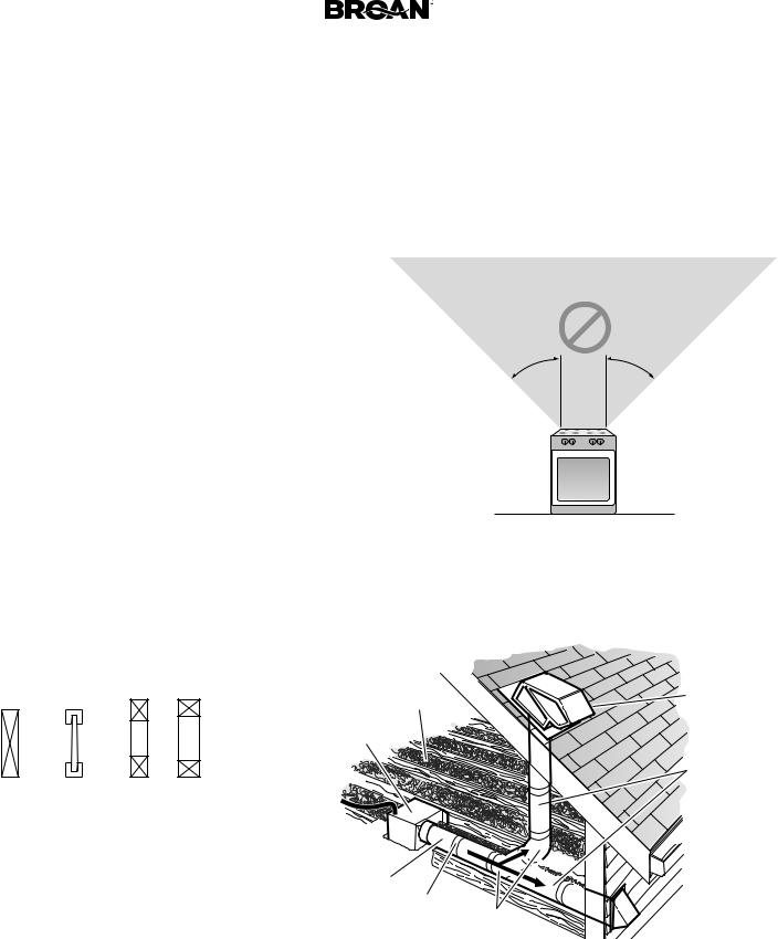
NOT FOR USE IN A COOKING AREA
Do not install above or inside this area
45° 45°
 Cooking
Equipment
Floor
Typical Installation
• Installation is the same for:
Joists |
I-Joists |
Trusses |
•Fits in 2" x 8" ceiling construction.
•Infinitely adjust the fan position between joists from 14" to 24" on center.
INSULATION* (Place around and over Fan Housing.)
FAN
HOUSING
POWER  CABLE*

Seal gaps 
 around
  Housing.
ROUND
DUCT*
Seal duct *Purchase joints with separately. tape.
OR 
ROUND
ELBOWS*
ROOF CAP* (with built-in damper)
Keep duct runs short.
 WALL CAP* (with built-in damper)
The ducting from this fan to the outside of the building has a strong effect on the air flow, noise and energy use of the fan. Use the shortest, straighest duct routing possible for best performance, and avoid installing the fan with smaller ducts than recommended. Insulation around the ducts can reduce energy loss and inhibit mold growth. Fans installed with existing ducts may not achieve their rated airflow.
6-inch round rigid metal duct is recommended for best performance.
Page 3 |
XB50 n XB80 n XB110 Installation Guide |
New Construction Installation
Tools needed
•Power screwdriver with a Phillips bit
•Phillips screwdriver
•Flathead screwdriver
•Pliers
•Wire insulation stripper
•Wire cutter
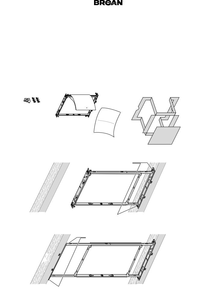
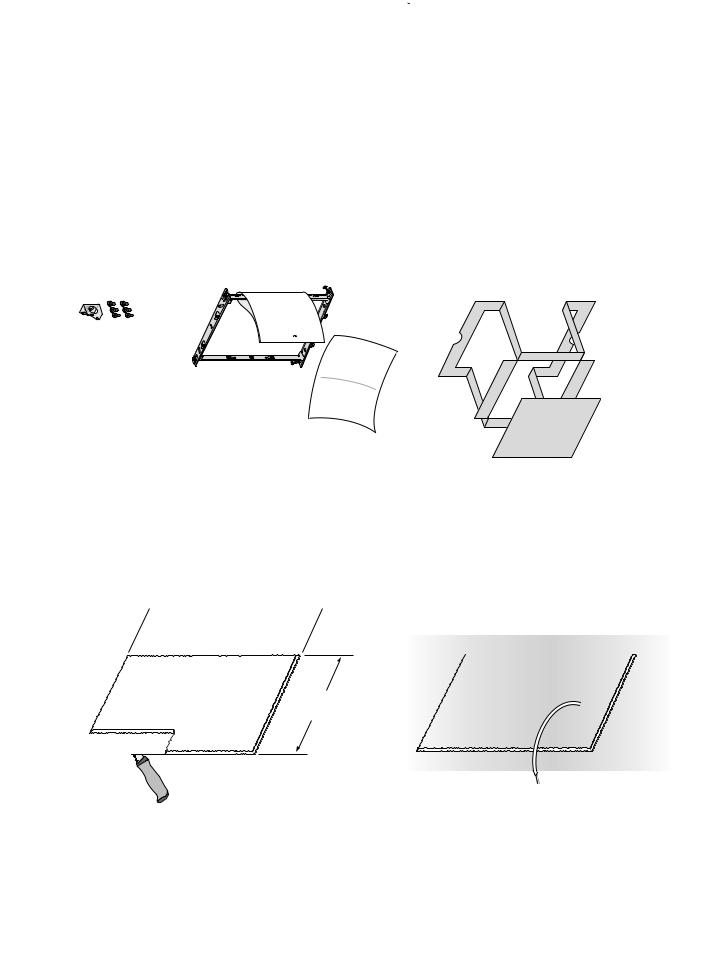
1 Remove Packaging
Parts Bag holds Knockout Plate and six (6) screws
Materials needed
•6" round metal ducting recommended for best performance. Use of other ducting is acceptable but may impact performance.
•Roof cap or wall cap (built-in damper recommended)
•Tape to seal duct connections
•Electrical wiring and supplies per local code requirements
Punch out Mask from packaging. See Step 6.
Remove
Instruction Sheet
2 MountingInstall |
2 |
|
|
Frame |
|
|
1 |
4

 3
3

Page 4 |
XB50 n XB80 n XB110 Installation Guide |
New Construction Installation
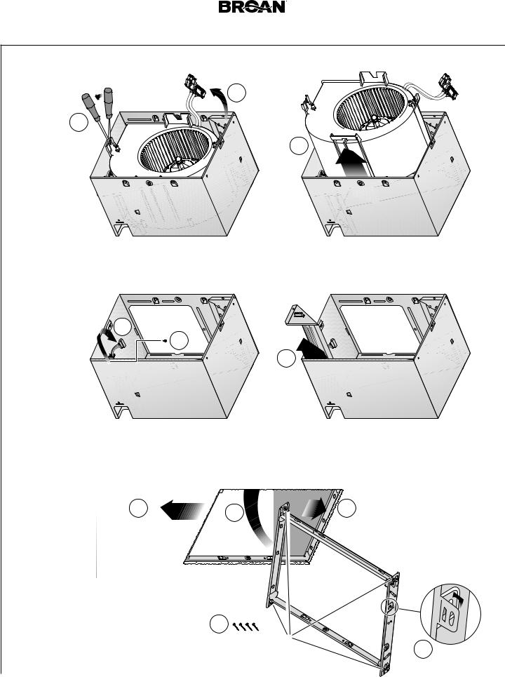
3 Snap-in and
Secure Housing
1
2 
 snap!
snap!

4
3 Screws from Parts Bag |
Position Housing between joists and crimp channel on both sides of Mounting Frame
to lock Housing in place.
Do not crimp Housing.
4 |
Attach Duct Connector and Ducting |
Top and bottom flanges |
|
|
go outside Housing |
|
Insert tab into slot |
|
inside Housing |
|
1 |
2 |
Screw from |
Parts Bag |
6" Ducting |
Tape |
3 |
|
Tape |
Tape |
4" Ducting |
|
||||
|
|
|
|
|
|
|
|
|
6" to 4" Reducer provided in select models |
||
Page 5  XB50 n XB80 n XB110 Installation Guide
New Construction Installation
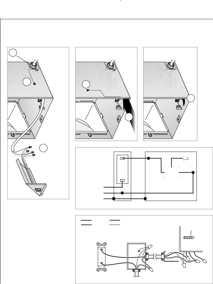
5 |
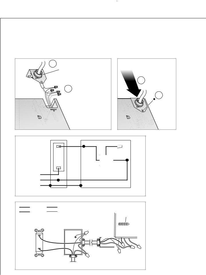
Connect Wires and Install Knockout Plate |
• Run 120VAC electrical wiring to the installation location. |
• Use proper UL-approved connectors to secure wiring to the Knockout Plate provided in Parts Bag.
• Connect wires as shown in wiring diagram.
1Attach cable clamp to Knockout Plate. Knockout Plate mounts to outside of Housing and may be
oriented as desired.
3
2 Connect wires
4
 Screw from Parts Bag
|
|
BLK |
BLK |
RED |
|
ON/OFF |
|
|
|
|
|
SWITCH |
|
|
|
WHT |
|
|
|
|
|
FAN |
|
|
|
|
|
|
|
|
BLK |
|
|
|
|
LINE |
WHT |
WHT |
|
|
|
IN |
GRD |
GRD |
|
|
|
|
|
|
|
||
|
SWITCH BOX |
|
UNIT |
|
|
BLACK |
RED |
|
|
|
|
WHITE |
GROUND (green or bare) |
|
RECEPTACLE |
||
|
|
|
|
|
|
ON/OFF |
|
|
|
|
|
SWITCH |
|
|
|
|
|
(purchase separately) |
SWITCH BOX |
|
|
|
|
|
|
|
|
KNOCKOUT |
|
|
|
|
|
PLATE |
|
|
|
120 VAC LINE IN |
|
|
|
Page 6 |
XB50 n XB80 n XB110 Installation Guide |
New Construction Installation
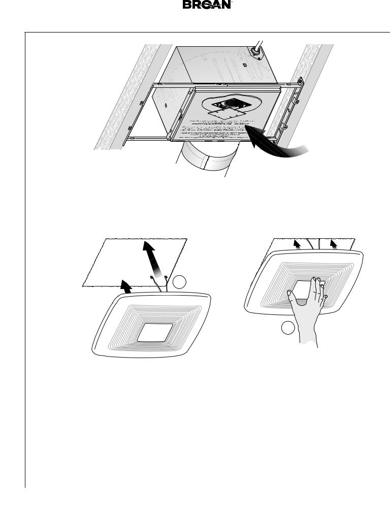
6 Insert Mask and
Finish Ceiling
• Install ceiling material.
• Cut out around Housing.
Mask protects unit during construction.
Remove before installing Grille.
CAUTION 
 IN ORDER TO PREVENT MOTOR/CONTROL DAMAGE:
If the blower was unplugged, power must be disconnected (see page 2, WARNING item 2) before inserting motor plugs into control assembly.
7 Install Grille |
1 |
2
See Page 12 for Operations, Cleaning and Maintenance, and Troubleshooting.
Page 7  XB50 n XB80 n XB110 Installation Guide
Retrofit Installation
Tools needed |
|
|
Materials needed |
||
• Power screwdriver with a Phillips bit |
• |
Ruler |
• Tape to seal duct connections |
||
• |
Phillips screwdriver |
• |
Pencil |
• Existing rigid duct will require the |
|
• |
Flathead screwdriver |
• |
Drywall saw |
addition of a short length of flexible duct |
|
|
|||||
• |
Pliers |
• Claw hammer or pry bar |
• Electrical wiring and supplies per |
||
local code requirements |
|||||
• |
Wire insulation stripper |
• |
Utility knife |
||
|
|||||
• |
Wire cutter |
|
|
|
|
1 Remove Packaging
Punch out Mask from packaging. See Step 12.
Remove
Instruction
Sheet
Parts Bag holds Knockout Plate and six (6) screws
2 Switch Off Power
WARNING
Before removing existing fan, switch power off at service panel and lock the service disconnecting means to prevent power from being switched on accidentally. When the service disconnecting means cannot be locked, securely fasten a prominent warning device, such as a tag, to the service panel.
3 Enlarge Ceiling Opening and Remove Existing Fan
 12" (30.5 cm)


 11" (27.9 cm)


 parallel with joists
2
|
Existing ductwork and |
1 |
wiring left in place |
|
4 Examine Wiring
Examine the existing wiring to make sure it is not damaged. If any damage is found,
DO NOT CONTINUE INSTALLATION of this product. Contact a qualified person(s) for repair.
Page 8 |
XB50 n XB80 n XB110 Installation Guide |
Retrofit Installation
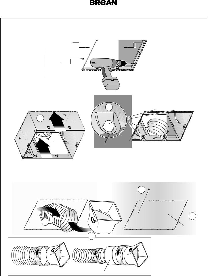
5 Remove Blower Assembly |
|
|
|
||
|
|
1 |
|
|
Set aside |
|
|
|
|
|
|
|
|
|
|
|
Blower |
2 |
|
|
|
|
Assembly |
Both sides |
|
|
3 |
|
|
|
|
|
|
|
|
6 Remove Wiring Panel |
|
Set aside |
|
|
|
|
|
|
Wiring Panel |
|
|
1 |
Set aside |
|
|
|
|
screw |
|
|
|
|
|
|
2 |
|
|
|
|
|
|
|
3 |
|
|
7 MountingInsert |
|
|
|
|
|
Frame |
|
|
|
|
|
|
4 |
3 |
|
5 |
|
|
|
|
|
|
|
|
|
1 |
|
|
|
|
|
Remove screws from |
2 |
|
|
|
|
Mounting Frame |
|
Bend up |
|
|
|
and set aside |
|
|
four tabs |
Page 9 |
XB50 n XB80 n XB110 Installation Guide |
Retrofit Installation
8 SecureMounting
Frame
Screws set aside
in Step 7
9 Snap-in Housing
1
 2
2


snap!
 Pull existing wiring into Housing as it is inserted into Mounting Frame
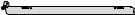
10 Attach Ducting and Duct Connector
|
|
|
4 |
Screw from |
|
|
|
|
Parts Bag |
Pull existing |
|
|
|
|
ductwork |
|
|
|
|
into Housing |
|
|
|
|
|
|
|
|
3 |
|
1 |
|
|
Insert tab into |
|
|
|
|
slot inside |
|
|
|
|
Housing |
6" Ducting |
Tape |
|
Tape |
|
4" Ducting |
Tape |
|
||
|
|
|
6" to 4" Reducer provided in select models
Page 10  XB50 n XB80 n XB110 Installation Guide
Retrofit Installation
11 |
Install Knockout Plate, Connect Wires and Reinstall Wiring Panel |
• Use proper UL-approved connectors to secure wiring to the Knockout Plate provided in Parts Bag. |
• Connect wires as shown in wiring diagram.
1 |
Attach cable clamp to Knockout |
|
Plate. Knockout Plate mounts to |
||
|
inside of Housing and may be |
|
|
|
oriented as |
|
|
desired. |
|
2 |
|
Screw from |
|
|
Parts Bag |
|
|
|
3 |
Connect |
|
|
wires |
Screw set |
|
|
|
|
|
aside in |
|
|
|
|
|
Step 6 |
|
|
|
|
|
5 |
|
|
|
|
|
|
|
|
|
|
6 |
|
4 |
|
|
|
|
|
|
BLK |
BLK |
RED |
|
ON/OFF |
|
|
|
|
|
SWITCH |
|
|
|
WHT |
|
|
|
|
|
FAN |
|
|
|
|
|
|
|
|
BLK |
|
|
|
|
LINE |
WHT |
WHT |
|
|
|
IN |
GRD |
GRD |
|
|
|
|
|
|
|
||
|
SWITCH BOX |
|
|
UNIT |
|
BLACK |
RED |
WHITE |
GROUND (green or bare) |
|
RECEPTACLE |
ON/OFF |
|
SWITCH |
|
(purchase separately) |
SWITCH BOX |
|
KNOCKOUT |
|
PLATE |
|
120 VAC LINE IN |
Page 11 |
|
XB50 n XB80 n XB110 Installation Guide |
Retrofit Installation |
|
|
12 |
Reinsert and Secure Blower Assembly |
|
CAUTION |
IN ORDER TO PREVENT MOTOR/CONTROL DAMAGE: |
|
Power must be disconnected (see page 2, WARNING item 2) before inserting motor plugs into control assembly.
1 |
2 |
3 |
Screws from Parts Bag
13 Install Grille |
If ceiling repairs are needed, place Mask in Housing after Blower Assembly is secured. See New Construction Installation Step 6.
Remove Mask before installing Grille.
1 |
2

Page 12
WARNING  Before servicing or cleaning unit, switch power off at service panel and lock the service disconnecting means to prevent power from being switched on accidentally. When the service disconnecting means cannot be locked, securely fasten a prominent warning device, such as a tag, to the service panel.
Operation
To Operate Fan
Use an ON/OFF switch to operate this ventilator.
It is normal for this ventilation fan to take approximately 5 seconds to start running after it is turned on.
Cleaning and Maintenance CAUTION 

IN ORDER TO PREVENT MOTOR/CONTROL DAMAGE:
DO NOT remove motor plug to stop spinning motor.
Power must be disconnected (see WARNING at top left of this page) before motor plug is removed or inserted into control assembly.
To Clean
For quiet and efficient operation, long life and attractive appearance, remove Grille and vacuum interior of unit with a dusting brush attachment.
The Motor is permanently lubricated and never needs oiling. If the motor bearings are making excessive or unusual noises, replace the Control Assembly and Motor.
XB50 n XB80 n XB110 Installation Guide
Troubleshooting
Symptom: The fan does not run.
•Check for an open fuse or circuit breaker in the building’s service panel.
•Check that the two (2) plug-in connections for the Motor and the Control are seated firmly in place.
•Check that the Blower Wheel spins freely.
Symptom: The fan runs erratically.
•Check that the Blower Wheel is firmly attached to the Motor shaft and both spin freely.
Symptom: The fan seems noisy.
•Check that the back draft damper in the fan’s Duct Connector pivots freely. Screws used to attach the duct to the Duct Connector may be preventing the damper from opening.
•Check that the back draft damper in the wall or roof cap pivots freely. These dampers are sometimes mistakenly painted shut or obstructed by bird and insect debris..
 Loading...