


INSTALLATION INSTRUCTIONS
HRV90H AND ERV90HC
Model no.: HRV90HT |
Model no.: HRV90HS |
(HRV with ports on top) |
(HRV with ports on sides) |
VB0082 |
VB0081 |
Model no.: ERV90HCT |
Model no.: ERV90HCS |
(ERV with ports on top) |
(ERV with ports on sides) |
VB0080 |
VB0079 |
RESIDENTIAL USE ONLY
READ AND SAVE THESE INSTRUCTIONS
06010C rev. E
ABOUT THIS MANUAL
Because of the large amount of models covered by this publication, the illustrations are typical ones. Some details of your unit may be slightly different than the ones shown.
Please take note that this manual uses the following symbols to emphasize particular information:
! WARNING
Identifies an instruction which, if not followed, might cause serious personal injuries including possibility of death.
CAUTION
Denotes an instruction which, if not followed, may severely damage the unit and/or its components.
NOTE: Indicates supplementary information needed to fully complete an instruction.
We welcome any suggestions you may have concerning this manual and/or the unit, and we would appreciate hearing your comments on ways to better serve you. Please contact us by phone at 1-800-558-1711.
ABOUT THESE UNITS
LIMITATION
For residential (domestic) installation only. This unit must be installed in accordance with all national and local regulations, building codes and safety codes.
! WARNING
TO REDUCE THE RISK OF FIRE, ELECTRIC SHOCK, OR INJURY TO PERSON(S) OBSERVE THE FOLLOWING:
1.Use this unit only in the manner intended by the manufacturer. If you have questions, contact the manufacturer at the address or telephone number listed in the warranty.
2.Before servicing or cleaning the unit, disconnect power cord from electrical outlet.
3.This unit is not designed to provide combustion and/or dilution air for fuel-burning appliances.
4.When cutting or drilling into wall or ceiling, do not damage electrical wiring and other hidden utilities.
5.Do not use this unit with any solid-state speed control device other than main optional wall control VT4W, and no other optional auxiliary wall controls than 60-minute crank timer and/or 20-minute lighted push button and/or Humidity Control.
6.This unit must be grounded. The power supply cord has a 3-prong grounding plug for your personal safety. It must be plugged into a mating 3-prong grounding receptacle, grounded in accordance with the national electrical code and local codes and ordinances. Do not remove the ground prong. Do not use an extension cord.
7.Do not install in a cooking area or connect directly to any appliances.
8.Do not use to exhaust hazardous or explosive materials and vapors.
CAUTION
1.To avoid prematurate clogged filters, turn OFF the unit during construction or renovation.
2.Please read specification label on product for further information and requirements.
3.Be sure to duct air outside – Do not intake / exhaust air into spaces within walls or ceiling or into attics, crawl spaces, or garage.
4.Intended for residential installation only in accordance with the requirements of NFPA 90B.
5.Do not run any air ducts directly above or closer than 2 ft (0.61 m) to any furnace or its supply plenum, boiler, or other heat producing appliance. If a duct has to be connected to the furnace return plenum, it must be connected not closer than 9’10” (3 m) from this plenum connection to the furnace.
6.The ductwork is intended to be installed in compliance with all local and national codes that are applicable.
- 2 -

TABLE OF CONTENTS
1.0 |
TECHNICAL DATA . . . . . . . . . . . . . . . . . . . . . . . . . . . . . . . . |
. . . . . . . . . . . . . . . . . . . . . . . . . .4-6 |
1.1 |
AIR DISTRIBUTION (NORMAL OPERATION) . . . . . . . . . . . . . . . . . . . . . |
. . . . . . . . . . . . . . . . . . . . . . . . . . . . . . . .4 |
1.2 |
AIR DISTRIBUTION (RECIRCULATION OR DEFROST MODE) . . . . . . . . . . |
. . . . . . . . . . . . . . . . . . . . . . . . . . . . . . . .4 |
1.3 |
SPECIFICATIONS . . . . . . . . . . . . . . . . . . . . . . . . . . . . . . . . . . . . . . . . |
. . . . . . . . . . . . . . . . . . . . . . . . . . . . . . .4 |
1.4 |
PERFORMANCE CHARTS . . . . . . . . . . . . . . . . . . . . . . . . . . . . . . . . . . |
. . . . . . . . . . . . . . . . . . . . . . . . . . . . . . .5 |
1.5 |
DIMENSIONS . . . . . . . . . . . . . . . . . . . . . . . . . . . . . . . . . . . . . . . . . . |
. . . . . . . . . . . . . . . . . . . . . . . . . . . . . . .6 |
1.6 |
CONTROLS AND LINKAGE POSSIBILITY . . . . . . . . . . . . . . . . . . . . . . . . |
. . . . . . . . . . . . . . . . . . . . . . . . . . . . . . .6 |
2.0 |
TYPICAL INSTALLATIONS . . . . . . . . . . . . . . . . . . . . . . . . . . . . |
. . . . . . . . . . . . . . . . . . . . . . . . .7-8 |
2.1 |
FULLY DUCTED SYSTEM . . . . . . . . . . . . . . . . . . . . . . . . . . . . . . . . . . |
. . . . . . . . . . . . . . . . . . . . . . . . . . . . . . .7 |
2.2 |
CENTRAL DRAW POINT . . . . . . . . . . . . . . . . . . . . . . . . . . . . . . . . . . . |
. . . . . . . . . . . . . . . . . . . . . . . . . . . . . . .7 |
2.3 |
SIMPLIFIED INSTALLATION . . . . . . . . . . . . . . . . . . . . . . . . . . . . . . . . . . |
. . . . . . . . . . . . . . . . . . . . . . . . . . . . . . .7 |
2.4 |
INSTALLATION FOR ERV UNITS ONLY . . . . . . . . . . . . . . . . . . . . . . . . . |
. . . . . . . . . . . . . . . . . . . . . . . . . . . . . . .8 |
3.0 |
INSTALLATION . . . . . . . . . . . . . . . . . . . . . . . . . . . . . . . . . . . . |
. . . . . . . . . . . . . . . . . . . . . . . .9-16 |
3.1 |
INSPECT THE CONTENT OF THE BOX . . . . . . . . . . . . . . . . . . . . . . . . . |
. . . . . . . . . . . . . . . . . . . . . . . . . . . . . . .9 |
3.2 |
LOCATING THE UNIT . . . . . . . . . . . . . . . . . . . . . . . . . . . . . . . . . . . . . |
. . . . . . . . . . . . . . . . . . . . . . . . . . . . . . .9 |
3.3 |
UNIT PREPARATION . . . . . . . . . . . . . . . . . . . . . . . . . . . . . . . . . . . . . |
. . . . . . . . . . . . . . . . . . . . . . . . . . . . . . .9 |
3.4 |
HOW TO HANG THE UNIT . . . . . . . . . . . . . . . . . . . . . . . . . . . . . . . . . |
. . . . . . . . . . . . . . . . . . . . . . . . . . . . . .10 |
3.5 |
PLANNING OF THE DUCTWORK . . . . . . . . . . . . . . . . . . . . . . . . . . . . . |
. . . . . . . . . . . . . . . . . . . . . . . . . . . . . .10 |
3.6 |
INSTALLING THE DUCTWORK AND REGISTERS . . . . . . . . . . . . . . . . . . . |
. . . . . . . . . . . . . . . . . . . . . . . . . . .10-12 |
3.7 |
CONNECTING THE DUCT TO THE UNIT . . . . . . . . . . . . . . . . . . . . . . . . |
. . . . . . . . . . . . . . . . . . . . . . . . . . . . . .13 |
3.8 |
INSTALLING THE TANDEM® TRANSITION KIT . . . . . . . . . . . . . . . . . . . . . |
. . . . . . . . . . . . . . . . . . . . . . . . . . .13-15 |
3.9 |
INSTALLING 2 EXTERIOR HOODS . . . . . . . . . . . . . . . . . . . . . . . . . . . |
. . . . . . . . . . . . . . . . . . . . . . . . . . . . . . .16 |
4.0 |
CONTROLS . . . . . . . . . . . . . . . . . . . . . . . . . . . . . . . . . . . . . |
. . . . . . . . . . . . . . . . . . . . . . .17-19 |
4.1 |
INTEGRATED CONTROL . . . . . . . . . . . . . . . . . . . . . . . . . . . . . . . . . . . |
. . . . . . . . . . . . . . . . . . . . . . . . . . . . . .17 |
4.2 |
ELECTRICAL CONNECTION TO OPTIONAL WALL CONTROLS . . . . . . . . . . |
. . . . . . . . . . . . . . . . . . . . . . . . . . .17-18 |
4.3 |
VT4W OPTIONAL MAIN WALL CONTROL OPERATION . . . . . . . . . . . . . . |
. . . . . . . . . . . . . . . . . . . . . . . . . . . . . .18 |
4.4 |
OPTIONAL AUXILIARY WALL CONTROLS OPERATION . . . . . . . . . . . . . . |
. . . . . . . . . . . . . . . . . . . . . . . . . . . . . .19 |
5.0 |
ELECTRICAL CONNECTION TO THE FURNACE . . . . . . . . . . . . . . |
. . . . . . . . . . . . . . . . . . . . . . . . . .19 |
6.0 |
WIRING DIAGRAM . . . . . . . . . . . . . . . . . . . . . . . . . . . . . . . . |
. . . . . . . . . . . . . . . . . . . . . . . . . .20 |
7.0 |
BALANCING THE UNIT . . . . . . . . . . . . . . . . . . . . . . . . . . . . . . |
. . . . . . . . . . . . . . . . . . . . . . . . . .22 |
8.0 |
CONNECTING THE DRAIN . . . . . . . . . . . . . . . . . . . . . . . . . . . |
. . . . . . . . . . . . . . . . . . . . . . . . . .21 |
9.0 |
MAINTENANCE . . . . . . . . . . . . . . . . . . . . . . . . . . . . . . . . . . . |
. . . . . . . . . . . . . . . . . . . . . . .23-24 |
9.1 |
BIANNUAL MAINTENANCE . . . . . . . . . . . . . . . . . . . . . . . . . . . . . . . . . . |
. . . . . . . . . . . . . . . . . . . . . . . . . . .23-24 |
9.2 |
ANNUAL MAINTENANCE . . . . . . . . . . . . . . . . . . . . . . . . . . . . . . . . . . . |
. . . . . . . . . . . . . . . . . . . . . . . . . . . . . .24 |
10.0 |
SERVICE PARTS . . . . . . . . . . . . . . . . . . . . . . . . . . . . . . . . . . |
. . . . . . . . . . . . . . . . . . . . . . . . . .25 |
11.0 |
TROUBLESHOOTING . . . . . . . . . . . . . . . . . . . . . . . . . . . . . . . |
. . . . . . . . . . . . . . . . . . . . . . . . . .26 |
- 3 -
1. TECHNICAL DATA
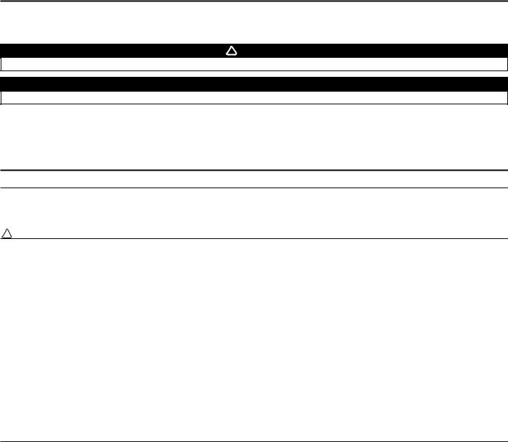
1.1 AIR DISTRIBUTION (NORMAL OPERATION)
|
HRV |
|
|
|
|
|
|
ERV |
||||
EXHAUST AIR- |
|
FRESH AIR |
EXHAUST AIR |
|
|
|
|
FRESH AIR |
||||
FROM BUILDING |
|
FROM OUTSIDE |
FROM BUILDING |
|
|
FROM OUTSIDE |
||||||
FRESH AIR |
|
EXHAUST AIR |
FRESH AIR |
|
|
|
|
EXHAUST AIR |
||||
TO BUILDING |
|
TO BUILDING |
|
|
|
|
TO OUTSIDE |
|||||
|
TO OUTSIDE |
|
|
|
|
|
|
|||||
|
|
|
|
|
|
|
|
|
||||
|
|
|
|
|
|
|
|
|
|
|
||
|
VF0038 |
|
|
|
VF0039 |
|
|
|
|
|
|
|
|
|
|
|
|
|
|
|
|
|
|
|
|
1.2 AIR DISTRIBUTION (RECIRCULATION OR DEFROST MODE) |
|
|
|
|
|
|
|
|
||||
|
HRV |
|
|
|
|
|
|
ERV |
||||
EXHAUST AIR- |
|
|
|
EXHAUST AIR- |
|
|
|
|
|
|
||
FROM BUILDING |
|
|
|
FROM BUILDING |
|
|
|
|
|
|
||
FILTERED AIR |
|
|
|
FILTERED AIR |
|
|
|
|
|
|
||
TO BUILDING |
|
|
|
TO BUILDING |
|
|
|
|
|
|
||
|
VF0036 |
|
|
|
VF0037 |
|
|
|
|
|
|
|
|
|
|
|
|
|
|
|
|
|
|
||
|
Outside Temperature |
|
HRV and ERV Defrost Cycles |
|
||||||||
|
Celcius (°C) |
|
Fahrenheit (°F) |
|
Defrosting (min.) |
|
Operation time (min.) |
|
||||
|
|
|
|
|
|
|
|
between each defrost cycle |
|
|||
|
-5 to -27 |
|
23 to -17 |
|
9 |
|
|
23 |
|
|
|
|
|
-27 and less |
|
-17 and less |
|
10 |
|
|
22 |
|
|
|
|
1.3 SPECIFICATIONS |
|
|
|
|
|
|
|
|
|
|
|
|
|
|
|
|
|
|
|
|
|
||||
|
Model |
|
HRV |
|
|
|
ERV |
|
|
|||
|
Weight |
|
42 lb (19 kg) |
|
45 lb (20.4 kg) |
|
|
|||||
|
Oval Ports |
|
Fit 5” (127 mm) ducts |
|
Fit 5” (127 mm) ducts |
|
|
|
||||
|
Drain Diameter |
|
1/2” (12 mm) |
|
|
N/A |
|
|
|
|||
|
Installation |
|
Chains, springs and hooks (provided with the unit). |
|
|
|
||||||
|
Motor Speeds |
|
|
|
High and low speed |
|
|
|
|
|
|
|
|
Electrical supply |
|
120 V, 60 Hz |
|
120 V, 60 Hz |
|
|
|||||
|
Power Consumption |
|
150 watts |
|
|
160 watts |
|
|
|
|||
|
|
|
|
|
|
|
|
|
|
|
|
|
- 4 -

1. TECHNICAL DATA (CONT’D)
1.4PERFORMANCE CHARTS
1.4.1HRV UNITS
Ventilation Performance
EXT STATIC |
|
NET SUPPLY |
|
|
|
GROSS AIR FLOW |
|
||||||||||||||||
PRESSURE |
|
AIR FLOW |
|
|
SUPPLY |
|
|
EXHAUST |
|
||||||||||||||
Pa |
|
in.w.g. |
l/s |
|
|
cfm |
|
|
m3/h |
l/s |
|
cfm |
|
|
m3/h |
|
l/s |
|
|
cfm |
|
|
m3/h |
|
|
|
|
|
|
|
|
||||||||||||||||
25 |
|
.1 |
52 |
|
|
110 |
|
|
187 |
52 |
|
110 |
|
|
187 |
|
58 |
|
|
122 |
|
|
205 |
50 |
|
.2 |
50 |
|
|
106 |
|
|
180 |
50 |
|
106 |
|
|
180 |
|
55 |
|
|
116 |
|
|
198 |
75 |
|
.3 |
48 |
|
|
101 |
|
|
173 |
48 |
|
102 |
|
|
173 |
|
53 |
|
|
113 |
|
|
191 |
100 |
|
.4 |
45 |
|
|
96 |
|
|
162 |
46 |
|
97 |
|
|
166 |
|
50 |
|
|
107 |
|
|
180 |
125 |
|
.5 |
43 |
|
|
92 |
|
|
155 |
43 |
|
92 |
|
|
155 |
|
49 |
|
|
103 |
|
|
173 |
150 |
|
.6 |
41 |
|
|
87 |
|
|
148 |
41 |
|
87 |
|
|
148 |
|
45 |
|
|
96 |
|
|
162 |
175 |
|
.7 |
38 |
|
|
81 |
|
|
137 |
38 |
|
81 |
|
|
137 |
|
43 |
|
|
91 |
|
|
155 |
200 |
|
.8 |
35 |
|
|
75 |
|
|
126 |
36 |
|
76 |
|
|
130 |
|
40 |
|
|
85 |
|
|
144 |
NOTE: ALL SPECIFICATIONS ARE SUBJECT TO CHANGE WITHOUT NOTICE.
1.4.2 ERV UNITS
Ventilation Performance
EXT STATIC |
|
NET SUPPLY |
|
|
|
GROSS AIR FLOW |
|
||||||||||||||||
PRESSURE |
|
AIR FLOW |
|
|
SUPPLY |
|
|
EXHAUST |
|
||||||||||||||
Pa |
|
in.w.g. |
l/s |
|
|
cfm |
|
|
m3/h |
l/s |
|
cfm |
|
|
m3/h |
|
l/s |
|
|
cfm |
|
|
m3/h |
|
|
|
|
|
|||||||||||||||||||
|
|
|
|
|
|
||||||||||||||||||
25 |
|
.1 |
55 |
|
|
116 |
|
|
197 |
56 |
|
119 |
|
|
202 |
|
59 |
|
|
125 |
|
|
212 |
50 |
|
.2 |
53 |
|
|
113 |
|
|
192 |
55 |
|
116 |
|
|
197 |
|
57 |
|
|
121 |
|
|
206 |
75 |
|
.3 |
50 |
|
|
107 |
|
|
182 |
52 |
|
111 |
|
|
189 |
|
54 |
|
|
115 |
|
|
195 |
100 |
|
.4 |
49 |
|
|
104 |
|
|
177 |
50 |
|
107 |
|
|
182 |
|
53 |
|
|
112 |
|
|
190 |
125 |
|
.5 |
46 |
|
|
98 |
|
|
166 |
48 |
|
101 |
|
|
172 |
|
50 |
|
|
105 |
|
|
178 |
150 |
|
.6 |
44 |
|
|
94 |
|
|
160 |
46 |
|
97 |
|
|
165 |
|
47 |
|
|
100 |
|
|
170 |
175 |
|
.7 |
42 |
|
|
88 |
|
|
150 |
43 |
|
91 |
|
|
155 |
|
45 |
|
|
95 |
|
|
161 |
200 |
|
.8 |
39 |
|
|
82 |
|
|
139 |
40 |
|
84 |
|
|
143 |
|
42 |
|
|
90 |
|
|
153 |
NOTE: ALL SPECIFICATIONS ARE SUBJECT TO CHANGE WITHOUT NOTICE.
Energy Performance
|
SUPPLY |
|
NET AIR FLOW |
|
POWER |
SENSIBLE |
APPARENTLATENTRECOVERY/ |
|||||||
TEMPERATURE |
|
|
CONSUMEDRECOVERY |
SENSIBLEMOISTURE |
||||||||||
C° |
|
F° |
l/s |
|
|
cfm |
|
|
m3/h |
WATTS |
EFFICIENCYEFFECTIVENESSTRANSFER |
|||
|
|
|
||||||||||||
HEATING |
|
|
|
|
|
|
|
|
|
|
|
|
||
0 |
|
+32 |
23 |
|
|
48 |
|
|
82 |
68 |
66 |
78 |
0.07 |
|
0 |
|
+32 |
30 |
|
|
63 |
|
|
108 |
82 |
65 |
76 |
0.04 |
|
0 |
|
+32 |
44 |
|
|
93 |
|
|
157 |
116 |
59 |
68 |
0.04 |
|
|
|
|
|
|
|
|
|
|
|
|
|
|
|
|
-25 |
|
-13 |
30 |
|
|
63 |
|
|
108 |
110 |
55 |
81 |
0.08 |
|
|
|
|
|
|
|
|
|
|
|
|
|
|
|
|
COOLING |
|
|
|
|
|
|
|
|
TOTALRECOVERY EFFICIENCY |
|||||
+35 |
|
+95 |
- |
|
|
- |
|
|
- |
- |
|
Not tested |
|
|
|
|
|
- |
|
|
- |
|
|
- |
|
|
|
|
|
Energy Performance
|
SUPPLY |
|
NET AIR FLOW |
|
POWER |
SENSIBLE |
APPARENT |
LATENTRECOVERY/ |
|||||
TEMPERATURE |
|
|
CONSUMEDRECOVERY |
SENSIBLEMOISTURE |
|||||||||
C° |
|
F° |
l/s |
|
|
cfm |
|
|
m3/h |
WATTS |
EFFICIENCYEFFECTIVENESSTRANSFER |
||
|
|
|
|||||||||||
HEATING |
|
|
|
|
|
|
|
|
|
|
|
||
0 |
|
+32 |
22 |
|
|
46 |
|
|
79 |
70 |
67 |
82 |
0.60 |
0 |
|
+32 |
30 |
|
|
64 |
|
|
108 |
85 |
65 |
77 |
0.54 |
0 |
|
+32 |
45 |
|
|
91 |
|
|
155 |
127 |
61 |
73 |
0.49 |
|
|
|
|
|
|
|
|
|
|
|
|
|
|
-25 |
|
-13 |
30 |
|
|
64 |
|
|
108 |
102 |
56 |
78 |
0.50 |
|
|
|
|
|
|
|
|
|
|
|
|
|
|
COOLING |
|
|
|
|
|
|
|
|
TOTALRECOVERY EFFICIENCY |
||||
+35 |
|
+95 |
23 |
|
|
46 |
|
|
166 |
68 |
|
49 |
|
|
|
|
- |
|
|
- |
|
|
- |
|
|
|
|
- 5 -
1. TECHNICAL DATA (CONT’D)
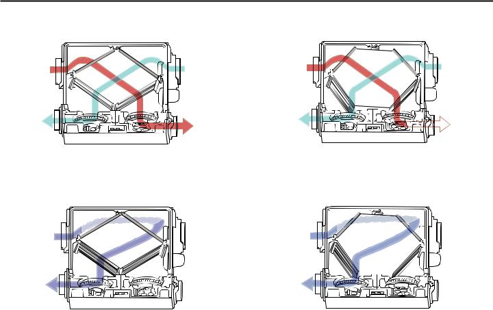
1.5DIMENSIONS
1.5.1 DIMENSIONS FOR PORTS ON SIDES UNITS
HRV
|
27 1 16” (688 mm) |
|
1913 16” (503 mm) |
4’’ (102 mm) |
22 9 16” (574 mm) |
|
|
|
|
13¾” |
12 3 16” |
6’’ (152 mm) |
|
(310 mm) |
|
|
(349 mm) |
||
|
|
|
|
|
2” (51 mm) |
|
|
VK0055 |
|
|
|
|
ERV |
|
|
|
27 1 16” (688 mm) |
|
1913 16” (503 mm) |
4’’ (102 mm) |
22 9 16” (574 mm) |
|
|
|
|
|
12 3 16” |
6’’ (152 mm) |
|
|
(310 mm) |
 2” (51 mm)
VK0057
1.5.2 DIMENSIONS FOR PORTS ON TOP UNITS
HRV |
|
ERV |
|
|
|
191316” |
4’’ (102 mm) |
4’’ (102 mm) |
|
|
191316” |
||
(503 mm) |
|
(503 mm) |
|
|
6’’ (152 mm) |
6’’ (152 mm) |
|
22 9 16” (574 mm) |
|
22 9 16” (574 mm) |
|
23 ¾” (603 mm) |
|
23 ¾” (603 mm) |
|
|
2½” |
2½” |
|
|
(64 mm) |
(64 mm) |
|
16 ¼” |
12 3 16” |
12 3 16” |
|
(413 mm) |
|||
(310 mm) |
(310 mm) |
||
|
|||
|
|
VK0058 |
|
VK0056 |
|
|
|
1.6 CONTROLS AND LINKAGE POSSIBILITY |
|
|
|
MAIN CONTROL |
AUXILIARY CONTROLS |
LINKAGE POSSIBILITY |
|
• VT4W |
• 20-MINUTE PUSH BUTTON TIMER |
• AIR HANDLER INTERLOCK |
|
|
• 60-MINUTE CRANK TIMER |
(USED WITH FORCED AIR SYSTEM) |
|
|
• HUMIDITY CONTROL |
|
- 6 -
2. TYPICAL INSTALLATIONS
Installations may vary according to the type of unit and the ports configuration (top or sides). Use the following illustrations as guidelines to help you decide on how the unit will be installed.
All the units should be hung from the joists.
In every case, bathroom fans and a range hood should be used to exhaust stale air. Also, for homes with more than one level, we recommend one exhaust register at the highest level.
There are 3 installation methods: Fully ducted, Central Draw Point and Simplified Installation. NOTE: An electrical outlet has to be available within 3 feet of the unit.
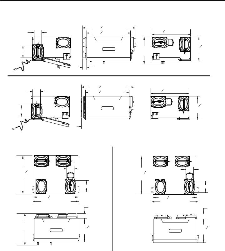
2.1 FULLY DUCTED SYSTEM (PRIMARILY FOR HOMES WITH RADIANT HOT WATER OR ELECTRIC BASEBOARD HEATING.)
Stale air coming from the registers located at the highest level of the house is exhausted to the outside. Fresh air from outside is filtered and supplied by the register located in the lowest liveable level.
Homes with more than one level require at least one exhaust register at the highest level.
See figure at right.
VH0055 |
2.2 CENTRAL DRAW POINT (CONNECTION TO A FORCED AIR SYSTEM.)
Stale air coming from the registers located at the highest level of the house is exhausted to the outside. Fresh air from outside is filtered and supplied to the return (plenum) or the supply duct of the forced air unit. See figure at right.
For this type of installation, it is not essential that the forced air system blower runs when the unit is in operation, but we recommend it.
NOTE: Home with multiple forced air systems should have one unit on each system.
VH0056 |
2.3 SIMPLIFIED INSTALLATION (CONNECTION TO A FORCED AIR SYSTEM)
Stale air is exhausted to the outside. Fresh air from outside is filtered and supplied to the return (plenum) or the supply duct of the forced air unit. See figure at right.
NOTE: It is possible to connect the outside fresh air duct to the supply duct of the forced air unit. To do so, the Automatic fresh air bypass must be used (part #: 15391). (See installation sheet included with the Automatic fresh air bypass).
To avoid cross-contamination and achieve the highest efficiencies, the Automatic fresh air bypass (part #15391) must be installed. If not, the forced air system blower must always be ON.
NOTE: Home with multiple forced air systems should have one unit on each system.
VH0057 |
- 7 -

2. TYPICAL INSTALLATIONS (CONT’D)
2.4INSTALLATION FOR ERV UNITS ONLY
2.4.1 GEOGRAPHICAL LOCATION
The ERV units are created to meet specific requirements related to geographical locations. Take a look at the map below; the shaded area shows the limits where the ERV unit can be installed. However, there is no geographical limitation for installing an HRV unit.
|
|
YELLOWKNIFE |
|
|
|
|
|
|
|
|
WHITEHORSE |
|
HAY RIVER |
|
|
|
|
|
|
|
|
|
FORT SMITH |
|
|
|
|
|
|
|
||
ANCHORAGE |
|
|
|
|
|
|
|
|
||
JUNEAU |
|
|
|
|
|
|
|
|
|
|
|
|
FORT MCMURRAY |
|
|
|
|
|
|
|
|
Prince Rupert |
|
GRANDE PRAIRIE |
|
|
|
|
|
|
|
|
|
|
EDMONTON |
|
|
|
|
|
|
|
GOOSE BAY |
|
|
|
|
|
|
|
|
|
|
|
|
JASPER |
PRINCE ALBERT |
|
|
|
|
LABRADOR CITY |
|||
|
KAMLOOPS |
SASKATOON |
|
|
|
|
|
|
|
|
|
|
|
|
|
|
|
SEPT-ILES |
|||
|
|
CALGARY |
REGINA |
WINNIPEG |
|
CHIBOUGAMAU |
||||
|
|
PENTICTON |
|
|
|
|||||
|
|
|
|
|
|
|
|
|||
VICTORIA |
LETHBRIDGE |
|
|
|
TIMMINS |
CHICOUTIMI |
|
GASPÉ |
||
|
|
|
|
|
||||||
|
|
|
|
MATANE |
|
|||||
|
|
|
|
|
|
|
|
VAL-DOR |
|
|
|
|
|
|
|
|
|
|
BATHURST |
||
|
|
|
|
|
|
|
|
|
||
|
OLYMPIA |
HELENA |
|
|
|
SUDBURY |
QUEBEC |
CHARLOTTETOWN |
||
|
|
BISMARCK |
|
|
|
|||||
|
|
|
|
NORTH BAY |
|
|||||
|
|
|
|
SAULT STE MARIE |
|
|
|
|||
|
|
|
|
|
ST. PAUL |
|
|
MONTRÉAL |
|
ST JOHN’ |
|
|
|
|
|
|
|
OTTAWA |
|
||
|
|
|
|
|
|
|
ST-JOHN |
HALIFAX |
||
|
SALEM |
|
|
|
|
|
|
|||
|
|
|
|
|
TORONTO |
|
|
|||
|
|
|
|
|
MADISON |
|
|
|||
|
|
BOISE |
|
|
|
|
|
|
|
|
|
|
|
|
|
DETROIT |
|
|
|
|
|
|
|
|
|
|
DES MOINES |
|
BOSTON |
|
||
|
|
|
|
|
|
|
|
|||
|
|
SALT LAKE CITY |
|
|
|
|
HARTFORD |
|
|
|
|
|
|
|
|
|
|
|
|
|
|
|
|
|
DENVER |
|
INDIANAPOLIS |
HARRISBURG |
|
|
||
|
|
RENO |
|
|
SPRINGFIELD |
COLUMBUS |
|
|
||
SACRAMENTO |
|
TOPEKA |
|
|
|
WASHINGTON |
|
|
||
|
|
|
|
|
|
|
|
|||
|
|
|
SANTA FE |
OKLAHOMA CITY |
NASHVILLE |
|
RALEIGH |
|
|
|
|
|
|
|
|
|
|
||||
|
|
|
|
|
|
|
|
|
||
|
|
PHOENIX |
|
|
ATLANTA |
COLUMBIA |
|
|
||
|
|
|
|
|
|
|
|
|||
|
|
|
|
AUSTIN |
BATON ROUGE |
|
|
|
|
|
VN0006 |
|
|
|
|
|
|
|
|
|
|
NOTE:The ERV unit is designed to assist in the management of humidity introduced into the home.
During cooling season, in extreme humidity conditions, the use of additional dehumidification unit may be required to quickly remove all excess moisture. During heating season, in extreme dryness conditions, the use of a humidifier may be required if the indoor air is still too dry.
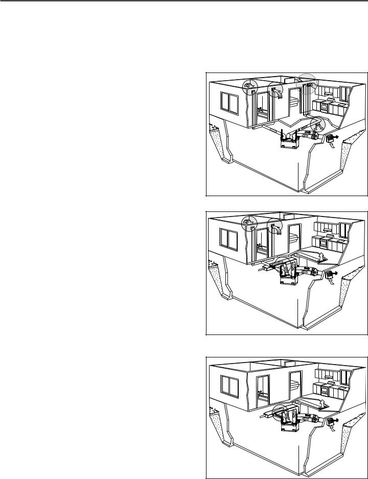
2.4.2 ERV UNITS ATTIC INSTALLATION
All 3 types of installations can be used in the attic (Fully ducted system, Central Draw Point or Simplified). The example shown below is a Simplified installation (connection to a forced air system).
CAUTION
Due to the potential temperature difference between the attic and the rest of the house, all unit ducts must be insulated.
CAUTION
The attic temperature must always be above 0°C (32°F).
Stale air is exhausted to the outside. Fresh air from outside is filtered and supplied to the return (plenum) of the forced air unit. See figure at right.
NOTE: It is possible to connect the outside fresh air duct to the supply duct of the forced air unit. To do so, the Automatic fresh air bypass must be used (part #: 15205). (See installation sheet included with the Automatic fresh air bypass).
To avoid cross-contamination and achieve the highest efficiencies, the Automatic fresh air bypass (part #15205) must be installed. If not, the forced air system blower must always be ON.
VH0058 |
NOTE: Home with multiple forced air systems should have 1 unit on each system.
- 8 -
 Loading...