


Broan AEEPD6SSE, AEEPD30SSE, AEEPD30SS, AEEPD18SS, AEEPD18SSE Installation Manual
...
MODEL AEEPD
AEEPD Telescopic Flue Cover for use with EPD61 Series Outdoor |
3 |
5 |
|||||
Range Hood. |
|
|
|
|
|
||
|
|
|
|
|
|
||
|
Model |
Length |
Width |
Collapsed |
Maximum |
|
|
|
|
|
|
Height |
Height |
|
2 |
|
AEEPD2445SS |
13” |
25” |
24” |
45” |
|
|
|
|
|
|||||
AEEPD2445SSE |
16” |
25” |
24” |
45” |
|
|
|
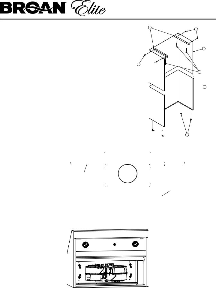
This Kit Contains: |
|
|
|
|
5 |
|
|
|
|
|
|
|
|
||
1. (1) Telescopic Flue Cover Bottom |
|
|
|
4 4 TOTAL |
|||
2. |
(1) Telescopic Flue Cover Top |
|
|
|
|
|
|
3. |
(2) Mounting Brackets |
|
|
|
|
|
|
|
(1) Hardware Bag (Service Part S97019391) Including: |
|
|
1 |
|||
4. |
(4) #10 x 2” Screws |
|
|
|
|
|
|
|
|
|
|
|
|
||
5. |
(8) # 8 x 3/8” Screws |
|
|
|
|
|
|
Follow hood installation manual steps 1-9 prior to installing Telescopic Flue Cover, and steps 11-12 to finalize hood installation.
Step 1: |
|
|
Remove protective coating from |
5 |
|
Telescopic Flue Cover. Be careful |
|
|
not to scratch surface of stainless |
24-3/4" |
|
steel. |
||
CENTER BRACKETS |
||
|
||
|
WITH CENTER OF HOOD |
Step 2:
Fasten Mounting Brackets (Item 3) to ceiling using dimensions shown and (4) #10 x 2” Screws (Included Item 4). Screws must be fastened into building structure. Do not fasten into drywall only or other non-load- bearing part of structure.
WALL 
TOP VIEW OF HOOD
 BOTH BRACKETS 2" FOR AEEPD2445SSE 1/2" FOR AEEPD2445SS
HOOD
Step 3:
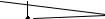
Fasten Telescopic Flue Cover to Hood using: (4) # 8 x 3/8” Screws (included Item 5). Arrows show hole locations on Hood. Hand tighten screws only.
Step 4:
Extend Telescopic Flue Cover and fasten to Mounting Brackets (Item 3) with (4) # 8 x 3/8” Screws (Included Item 5).
MODÈLE AEEPD
Conduit décoratif télescopique AEEPD pour hottes extérieures de Série EPD61.
Modèle |
Longueur |
Largeur |
Hauteur - |
Hauteur |
|
|
|
comprimé |
maximale |
|
|
|
|
|
AEEPD2445SS |
33 cm |
63,5 cm |
61 cm |
114,3 cm |
|
(13 po) |
(25 po) |
(24 po) |
(45 po) |
|
|
|
|
|
AEEPD2445SSE |
40,6 cm |
63,5 cm |
61 cm |
114,3 cm |
|
(16 po) |
(25 po) |
(24 po) |
(45 po) |
|
|
|
|
|
Cet ensemble contient :
1.(1) Conduit décoratif télescopique inférieur
2.(1) Conduit décoratif télescopique supérieur
3.(2) Brides de montage
(1) Sachet de quincaillerie (pièce n° S97019391) incluant :
4.(4) Vis #10 x 2 po (51 mm)
5.(8) Vis # 8 x 3/8 po (9,5 mm)
Suivez les étapes 1-9 du manuel d’installation de la hotte avant de poser le conduit télescopique décoratif, puis les étapes 11-12 pour finaliser l’installation de la hotte.
3 |
5 |
|
2
5 
4 4 AU TOTAL
 1
1
 5
5
Étape 1 : |
|
|
|
|
|
|
|
|
|
|
|
|
|
|
|
|
|
Enlevez la pellicule protectrice |
|
|
|
|
|
|
|
|
|
|
|
|
|
|
|
|
|
du conduit décoratif télescopique. |
|
|
|
|
|
|
24,75 PO (62,9 CM) |
|
|
|
|
|
|
|
|
|
|
Prenez garde de ne pas égratigner |
|
|
|
|
|
CENTRER LES BRIDES SUR |
|
|
|
|
|
|
|
|
|||
la surface d’acier inoxydable. |
|
|
|
|
|
|
|
|
|
|
|
|
|
||||
|
|
|
|
|
LE CENTRE DE LA HOTTE |
|
|
|
|
|
|
|
|
||||
|
|
|
|
|
|
|
|
|
|
|
|
||||||
|
|
|
|
|
|
|
|
|
|
|
|
|
|
|
|
|
|
|
MUR |
|
|
|
|
|
|
|
|
|
|
|
|
LES DEUX BRIDES |
|||
Étape 2 : |
|
|
|
|
|
|
|
|
|
|
|
2 PO (51 MM) POUR |
|||||
|
|
|
|
|
|
|
|
|
|
|
|
||||||
|
|
|
|
|
|
|
|
|
|
|
|
|
AEEPD2445SSE |
||||
Fixez les brides de montage (article 3) |
|
|
|
|
|
|
|
|
|
|
|
|
|
||||
|
|
|
|
|
|
|
|
|
|
|
1/2 PO (13 MM) POUR |
||||||
au plafond selon les dimensions |
|
|
|
|
|
|
|
|
|
|
|
||||||
|
|
|
|
|
|
|
|
|
|
|
|
|
|
AEEPD2445SS |
|||
indiquées à l’aide de (4) vis #10 x 2 po |
|
|
|
|
|
|
|
|
|
|
|
|
|
|
|
HOTTE |
|
(51 mm) (incluses - article 4). Les vis |
|
|
|
|
|
|
|
|
|
|
|
|
|
|
|
||
|
|
|
|
|
|
|
|
|
|
|
|
|
|
|
|
|
|
doivent être fixées dans la charpente |
|
|
|
|
|
|
|
|
|
|
|
|
|
|
|
|
|
de l’habitation. Ne les fixez pas dans |
|
|
|
|
|
|
|
|
|
|
|
|
|
|
|
|
|
une cloison sèche ni dans toute autre |
|
|
|
|
|
|
|
|
|
|
|
|
|
|
|
|
|
élément de structure ne pouvant pas |
|
|
|
|
|
|
|
|
|
|
|
|
|
|
|
|
|
supporter une charge. |
|
|
|
|
|
VUE DU HAUT DE LA HOTTE |
|||||||||||
Étape 3 :
Fixez le conduit décoratif télescopique au boîtier de la hotte :
(4) Vis # 8 x 3/8 x po (9,5 mm) (incluses - article 5). Les flèches montrent la position des trous sur la hotte. Ne serrez les vis qu’à la main.
Étape 4 :
Déployez le conduit décoratif télescopique et fixez-le aux brides de montage (article 3) avec (4) vis # 8 x 3/8 po
(9,5 mm) (incluses - article 5).
 Loading...