


413601
Broan 413601, 414201, 414204, 424201, 414202 Installation Manual
...
!
!
!
!
!
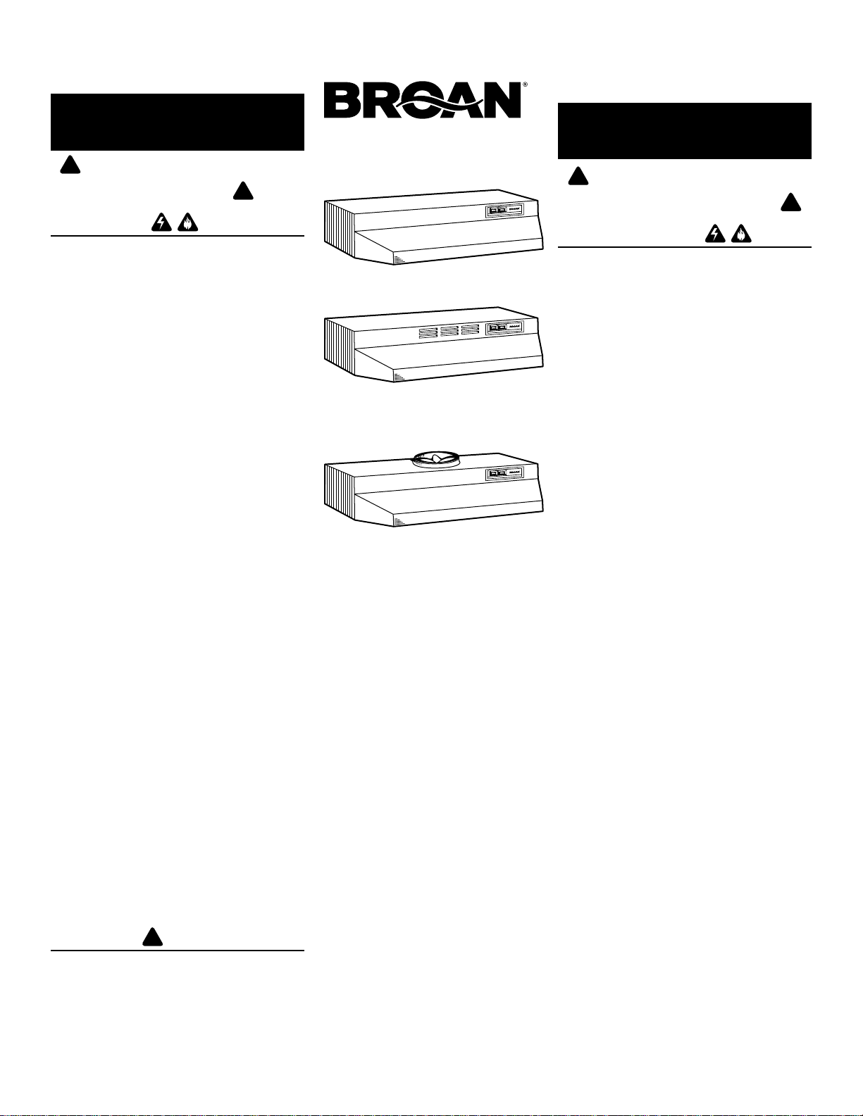
ECONOMY RANGE HOOD
INSTALLATION INSTRUCTIONS
INSTRUCCIONES DE INSTALACION
DE LOS EXTRACTORES TIPO
ECONOMICO
READ AND SAVE
THESE INSTRUCTIONS
INTENDED FOR DOMESTIC
COOKING ONLY.
WARNING
TO REDUCE THE RISK OF FIRE, ELECTRIC SHOCK,
OR INJURY TO PERSONS, OBSERVE THE FOLLOWING:
1. Use this unit only in the manner intended by the manufacturer. If you have questions, contact the manufacturer at the address or telephone number listed in the
warranty.
2. Before servicing or cleaning unit, switch power off at
service panel and lock the service disconnecting
means to prevent power from being switched on accidentally. When the service disconnecting means cannot be locked, securely fasten a prominent warning
device, such as a tag, to the service panel.
3. Installation work and electrical wiring must be done
by a qualified person(s) in accordance with all applicable codes and standards, including fire-rated construction codes and standards.
4. Sufficient air is needed for proper combustion and exhausting of gases through the flue (chimney) of fuel
burning equipment to prevent backdrafting. Follow the
heating equipment manufacturer’s guideline and safety
standards such as those published by the National Fire
Protection Association (NFPA), and the American Society for Heating, Refrigeration and Air Conditioning Engineers (ASHRAE), and the local code authorities.
5. When cutting or drilling into wall or ceiling, do not damage electrical wiring and other hidden utilities.
6. To reduce the risk of fire or electric shock, do not use
this range hood with an additional speed control device.
7. Ducted fans must always be vented to the outdoors.
8. To reduce the risk of fire, use only metal ductwork.
9. Use with approved cord-connection kit only.
10. This unit must be grounded.
TO REDUCE THE RISK OF A RANGE TOP GREASE
FIRE:
1. Never leave surface units unattended at high settings.
Boilovers cause smoking and greasy spillovers that
may ignite. Heat oils slowly on low or medium settings.
2. Always turn hood ON when cooking at high heat or
when cooking flaming foods.
3. Clean ventilating fans frequently. Grease should not
be allowed to accumulate on fan or filter.
4. Use proper pan size. Always use cookware appropriate for the size of the surface element.
TO REDUCE THE RISK OF INJURY TO PERSONS IN
THE EVENT OF A RANGE TOP GREASE FIRE, OBSERVE THE FOLLOWING:*
1. SMOTHER FLAMES with a close-fitting lid, cookie
sheet, or metal tray, then turn off the burner. BE CAREFUL TO PREVENT BURNS. If the flames do not go
out immediately, EVACUATE AND CALL THE FIRE DEPARTMENT.
2. NEVER PICK UP A FLAMING PAN - You may be
burned.
3. DO NOT USE WATER, including wet dishcloths or towels - a violent steam explosion will result.
4. Use an extinguisher ONLY if:
A. You know you have a Class ABC extinguisher and
you already know how to operate it.
B. The fire is small and contained in the area where it
started.
C. The fire department is being called.
D. You can fight the fire with your back to an exit.
* Based on “Kitchen Fire Safety Tips” published by NFPA.
CAUTION
1. For general ventilating use only. Do not use to exhaust
hazardous or explosive materials and vapors.
2. To avoid motor bearing damage and noisy and/or
unbalanced impellers, keep drywall spray, construction
dust, etc. off power unit.
3. For best capture of cooking impurities, your range hood
should be mounted 18-24" above the cooking surface.
4. Please read specification label on product for further
information and requirements.
To register this product visit
www.broan.com
DOMÉSTICO SOLAMENTE.
ADVERTENCIA
40000 HOOD
EXTRACTOR 40000
41000 & 41000MX SERIES/
MICROTEK
SISTEMA I DE LA SERIE
MICROTEK® 41000 Y 41000MX
42000 & 42000D HOODS
EXTRACTOR 42000
®
SYSTEM I
INSTALLER: Leave This Manual
With Homeowner.
HOMEOWNER: Use and Care
Information on Page 5.
INSTALADOR: Deje este manual con el
dueño de la casa.
DUEÑO DE LA CASA: Información acerca d
el uso y los cuidados en la página 5.
PARA REDUCIR EL RIESGO DE INCENDIO, CHOQUE
ELECTRICO, O LESION A PERSONAS, PROCURE LO
SIGUIENTE:
1. Utilice esta unidad sólo en la manera prescrita por el
2. Antes de limpiar o de poner en servicio la unidad,
3. Todo trabajo de instalación y cableado eléctrico debe
4. Aire suficiente es necesario para facilitar la combustión
5. A cortar o perforar la pared o el techo, no dañe el
6. Para reducir el riesgo de incendio o de descarga
7. Los abanicos con ducto deberán siempre tener una
8. Para reducir el riesgo de incendio, use sólo ductos de
9. Uso con el kit aprobado del la conexión de la cuerda
10. Esta unidad se debe instalar con tierra efectiva.
PARA REDUCIR EL RIESGO DE INCENDIO DEBIDO A
GRASA ACUMULADA EN LAS HORNILLAS:
1. Nunca deje sin atender las unidades de superficie
2. Siempre ENCIENDA la campana cuando cocine con
3. Limpie con frecuencia los ventiladores. No debe permitir
4. Utilice un sartén de tamaño adecuado. Siempre utilice
PA R A REDUCIR EL RIESGO DE LESION A PERSONAS
RESULTADO DE UN INCENDIO DEBIDO A GRASA
ACUMULADA EN LAS HORNILLAS, PROCURE LO
SIGUIENTE:*
1. AHOGUE LAS LLAMAS con una tapa ajustada o
2. NO LEVANTE NUNCA UNA SARTEN QUE ESTE EN
3. NO UTILICE AGUA, incluyendo toallas de cocina
4. Utilice un extinguidor SOLAMENTE si:
LEA Y CONSERVE
ESTAS INSTRUCCIONES
PREVISTO PARA COCINAR
fabricante. Si tiene usted alguna pregunta, comuníquese
con el fabricante a la dirección o el teléfono indicados
en la garantía.
apague el interruptor en el panel de servicio, y asegure
el panel de servicio para evitar que se encienda
accidentalmente. Cuando el dispositivo para
desconectar el servicio eléctrico no puede ser cerrado
con algún tipo de traba, sujete fuertemente al panel de
servicio, una etiqueta de advertencia prominente.
ser realizado por personal calificado y de acuerdo con
todos los códigos y normas pertinentes, incluyendo los
códigos y normas relacionados con construcción
clasificada para incendio.
adecuada y la salida apropiada de gases por la
chimenea de la unidad y para evitar corrientes de aire
invertidas. Siga las instrucciones y medidas de
seguridad del fabricante del equipo y de las sociedades
profesionales de equipos de calentadores y los
reglamentos de seguridad locales.
cableado eléctrico u otros servicios públicos ocultos a
la vista.
eléctrica, no utilice este ventilador con ningún dispositivo
de una control de velocidad de estado sólido adicional.
salida hacia el exterior.
metal.
solamente.
cuando tengan ajustes altos. Los reboses pueden
provocar humo y derrames grasosos que se pueden
incendiar. Caliente lentamente el aceite en un ajuste
bajo o medio.
alta temperatura o cuando cocine alimentos que se
puedan incendiar.
que la grasa se acumule en el ventilador ni en el filtro.
el utensilio adecuado al tamaño del elemento de
superficie.
charola de metal, después apague la hornilla. TENGA
CUIDADO A FIN DE EVITAR QUEMADURAS. Si las
llamas no se apagan de inmediato, EVACUE Y AVISE
A LOS BOMBEROS.
LLAMAS - Usted se podrá quemar.
mojadas - puede resultar una explosión de vapor violenta.
A. Usted sabe que tiene un extinguidor de clase
ABC y lo sabe utilizar.
B. El incendio es pequeño y contenido dentro del
área donde se inició.
C. Los bomberos han sido avisados.
D. Usted puede combatir el incendio con una salida a
su espalda.
* Basado en las recomendaciones para “Seguridad en
la Cocina” publicadas por la NFPA de los EEUU.
!
TOOLS AND
MATERIALS REQUIRED
Drill, electric or ratchet drive
1/8" Drill bit for drilling pilot holes
1-1/4" wood bit for drilling electrical wiring access
hole
One straight blade and one phillips head screw-
driver
Pliers
Pencil and ruler and/or tape measure
Saber saw or keyhole saw for cutting 1" x 2" wood
strips to length and cutting wall or cabinet openings
Caulking, metal snips, duct tape, duct (with elbows
and transition, if necessary) and roof or wall cap,
as required
Electrical wiring and supplies of type to comply
with local codes
The following materials are required only for installations on recessed bottom kitchen cabinets:r Ducted
Two 1" x 2" x 12" (approximate length) wood strips
(purchase locally)
Four 1-1/4" long flat head wood screws (purchase
locally)
PLANNING DUCTWORK
INSTALLATION
(This section for 40000 and 42000 hoods only. 41000
hoods skip this section and go on to “Prepare the
Hood”.)
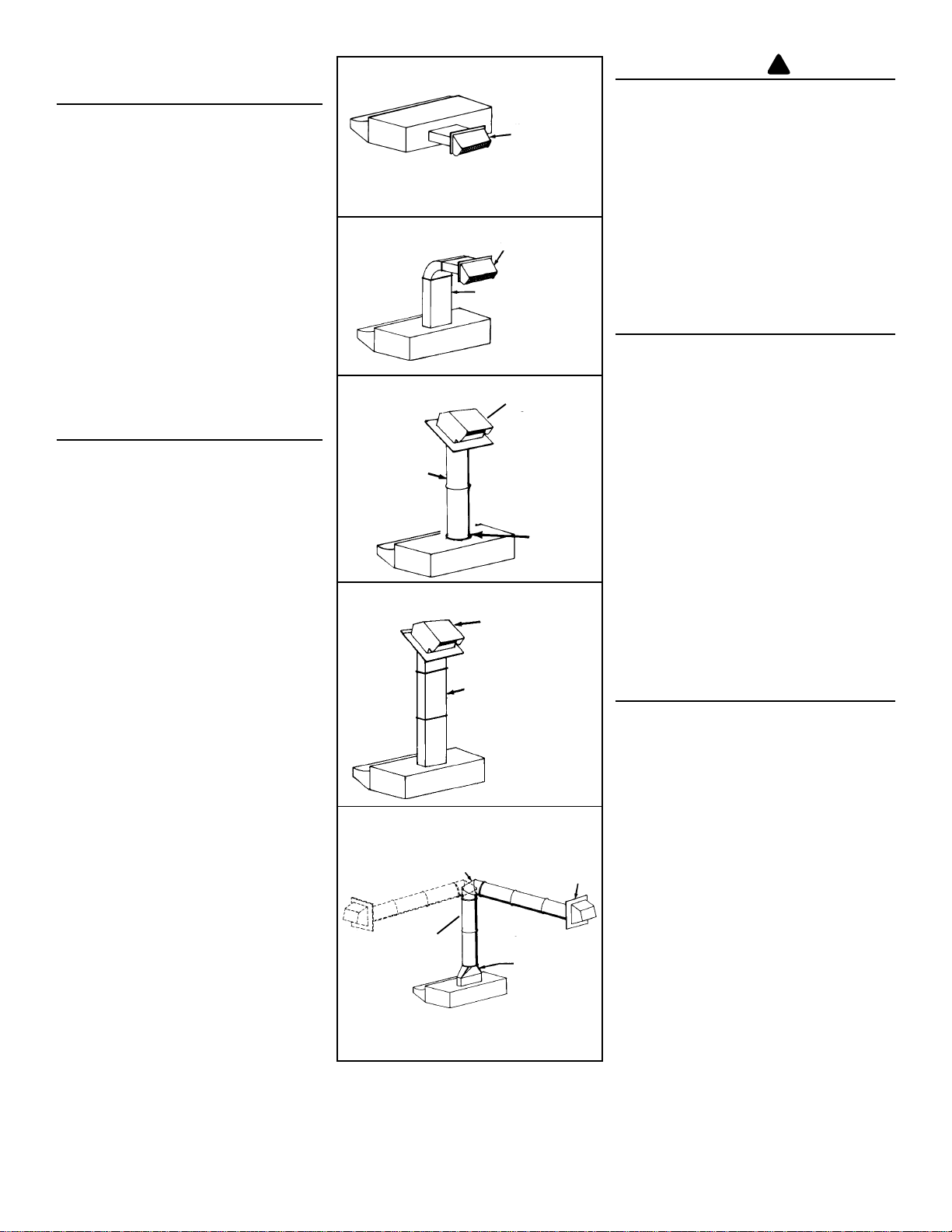
Begin planning ductwork by deciding where the duct
will run between the range hood and the outside. For
best performance, use the shortest possible duct run
and a minimum number of elbows. There are several
choices shown - FIGS. A - F below.
FIG. A. Ducting directly through the wall (for range
hoods mounted on an exterior wall). Shown are two
ways to duct through an outside wall. If a wall cap is
used directly off the back of the hood, special care must
be taken to make sure that the damper in the damper/
duct connector on the hood and damper in the wall
cap do not interfere with each other when the hood is
operating. This could result in either inadequate air
delivery or backdrafts. If this condition does exist, remove the hood damper flap. Sometimes when using a
wall cap it is easier to duct vertically and then use an
elbow as shown in FIG. B.
In more complex ducting situations, a 3-1/4" x 10" rectangular ducting range hood (40000 hood) can be converted to a round duct by means of a transition.
FIG . C. Straight up through the roof using 7" round duct
(for single story installations - 42000 & 42000D hood
only).
FIG. D. Ducting straight up through the roof using
3-1/4" x 10" rectangular duct (for single story installations - 40000 hood only).
FIG. E. Ducting between the ceiling joists (for multistory installations) or through the soffit space above
the cabinets (where the soffit connects to an outside
wall).
FIG . F. Straight up through the roof using 6" round duct
(for single-story installations).
FIG. A
FIG. B
FIG. C
7" ROUND DUCT 407
DUCTO REDONDO
DE 7 PLG. 407
FIG. D
FIG. E
ADJUSTABLE ELBOW 419
CODO AJUSTABLE 419
6" ROUND DUCT 406
DUCTO REDONDO DE
6 PLG. 406
WALL CAP 639
CASQUETE DE
PARED 639
WALL CAP 639
CASQUETE DE PARED 639
3-1/4" X 10" DUCT 401
DUCTO DE
3-1/4 PLG.
10 PLG. 401
ROOF CAP 634
CASQUETE DE TECHO 634
ROOF CAP 634
CASQUETE
DE TECHO 634
3-1/4" X 10" DUCT 401
DUCTO DE
3-1/4 PLG. X 10 PLG. 401
X
MODEL 87
DAMPER
(INCLUDED ON
42000D HOODS)
REGISTRO
DE TIRO
MODELO 87
(INCLUIDO EN
CAMPANAS DE
42000D)
WALL CAP 641
CASQUETE
DE PARED 641
3-1/4" X 10" TO 6"
ROUND DUCT
TRANSITION 411
ADAPTADOR DE
UNA SALIDA DE
EXTRACTOR DE
3-1/4 PLG. X 10
PLG. A UN
DUCTO
CIRCULAR DE 6
PLG. 411
2
PRECAUCION
1. Solamente para uso general de ventilación. No utilice
para descargar materiales o vapores riesgosos o
explosivos.
2. Para evitar daños al motor y evitar que las navajas del
abanico emitan mucho ruido o estén fuera de balance,
mantenga el motor libre de pelusa, polvo, etc.
3. Para obtener mejores resultados en la captura de los
vapores de la estufa, el extractor debe montarse a entre
18 y 24 plg. sobre las hornillas de la estufa.
4. Por favor lea la etiqueta con las especificaciones del
equipo para otros requisitos y mayor información.
HERRAMIENTAS Y
MA TERIALES QUE SE
NECESIT AN PARA LA
INST ALACION
Taladro, eléctrico o clavador de trinquete
Taladro de 1/8 plg.
Broca de 1-1/4 plg. para taladrar un agujero para la
entrada de los cables eléctricos
Una cuchilla recta y un desarmador con punta
(estrella) phillips
Pinzas
Lapíz y regla o una cinta de medir
Serrucho de punta o serrucho para cortar
pedazos de madera en 1 plg. por 2 plg. a la medida y
para hacer las aberturas en las paredes o en los
gabinetes
Remachadora, pedazos de metal, cinta para
ductos, ducto (si es necesario con codos y
conexiones) y recubrimiento de pared o techo,
según sea necesario
Cables eléctricos y materiales que sean
aceptados por las leyes locales
El siguiente material sólo se necesita si se va a instalar
en la parte inferior de un gabinete de cocina:
Dos pedazos de madera con medidas aproximadas
de 1 plg. x 2 plg. x 12 plg.
Cuatro tornillos para madera con cabeza plana
de 1-1/4 plg.
PLANEANDO LA INSTALACION
DE LOS DUCTOS
(Esta sección es sólo para extractores modelos 40000
y 42000. Si su extractor es modelo 41000, sáltese esta
sección y continúe en la sección de “PREPARANDO
EL EXTRACTOR”.)
Inicie el plan para instalar los ductos decidiendo por dónde
va a pasar el ducto entre el extractor y la pared. Para
obtener un mejor funcionamiento, escoja la salida más
directa posible para el ducto, y el menor número de codos.
Existen diferentes opciones que se muestran en las
FIGURAS A a F enseguida.
FIG . A . Colocación directa a través de la pared (para los
extractores que están montados en una pared externa).
Enseguida se ilustran dos formas para colocar el ducto a
través de una pared externa. Si se utiliza directamente
un casquete de pared en la parte trasera del extractor,
debe tenerse especial cuidado para asegurarse de que
el regulador en el conector del ducto/regulador del extractor y el regulador en el casquete de la pared no se
obstaculicen entre ellos cuando el extractor esté en
funcionamiento. Esto puede dar como resultado que el
aire tenga una salida inadecuada o que existan corrientes
de aire invertidas. Algunas veces es más sencillo usar un
casquete de pared colocándolo verticalmente y usando
un codo como el mostrado en la FIG. B.
Si la colocación del ducto es más compleja, el extractor
del ducto rectangular de 3-1/4 plg. x 10 plg. puede
substituirse por un ducto rédondo equivalente.
FIG. C. Utilizando un ducto circular de 7 plg. en posición
vertical (para instalaciones individuales - solamente
extractores modelo 42000 y 42000D).
FIG. D. Utilizando un ducto rectangular de 3-1/4 plg. x 10
plg., colocándolo en posición vertical (para instalaciones
individuales - solamente extractores modelo 40000).
FIG. E. Colocándolo entre las vigas del techo (para las
instalaciones múltiples) o a través de un espacio de plafón
sobre los gabinetes (en donde el plafón se conecta a una
pared externa).
FIG. F. En posición vertical a través del techo, utilizando
un ducto circular de 6 plg. (sólo para instalaciones
individuales).
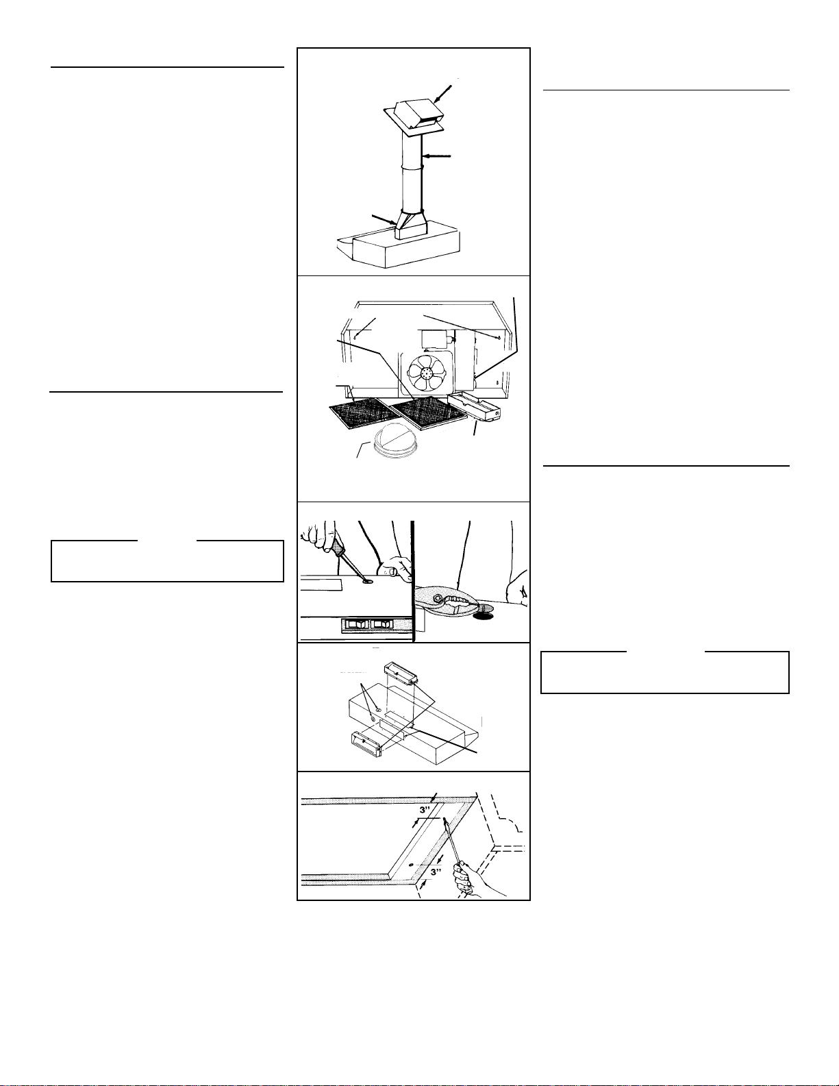
PREPARE THE HOOD
1. Unpack hood and check contents. You should receive:
1 - Aluminum Filter (40000 and 42000 & 42000D
hoods only)
1 - 3-1/4" x 10" Damper/Duct Connector (mounted
inside of hood for shipping only) (40000
hood only)
1 - Ductfree Microtek
hood only)
®
System I Filter (41000
1 - 7” Round Damper (42000D hoods only.)
2. Remove wiring box cover. Under cover find:
1 - Plastic Bag containing loose mounting hard-
ware
3. Remove top or rear electrical knockout. (FIG. 2)
4. (40000 hood ONLY) Remove duct knockout. Insert screwdriver under edge of knockout, break
tabs, and peel knockout back with pliers. (FIG. 3)
5. (40000 hood ONLY) Install damper/duct connector over opening made in STEP 4. Use #8B sheet
metal screws provided. (FIG. 3)
(42000 hood ONLY) Install Model 87 round damper
(purchase separately) over opening in top of hood.
(42000D hood ONL Y - Install 7” round damper (included) over opening on top of hood.
PREPARE THE
INSTALLA TION LOCATION
Omit STEP 1 if hood will be installed under cabinets
with flush bottom.
1. (For installation on recessed bottom cabinets only)
Attach a wood filler strip at each side of recessed
area under cabinet. Use two 1" x 2" strips cut to
length. If recess is deeper than 1" use thicker strips.
Attach strips with 1-1/4" wood screws, 3" from each
end of strip. See FIG. 4.
2. Measure and mark the following (FIGS. 5A & 5B):
a.) Electrical wiring opening in wall or cabinet.
b.) Duct opening in wall or cabinet (40000, 42000
& 42000D hoods ONLY).
WHEN CUTTING OR DRILLING INTO WALL OR
CABINET, BE CAREFUL NOT TO CUT EXISTING
ELECTRICAL WIRING.
3. Use 1-1/4" bit to drill opening for electric wiring.
4. Cut out duct opening in wall or cabinet with saber
saw or keyhole saw.
5. Center hood in installation opening and trace keyhole slots onto wood filler strips on cabinet bottom.
6. Screw four #10 x 7/8 wood screws into exact center
of narrow end of traced keyhole slots. Allow 3/8" of
screws to project, so that hood can be fitted into place
later.
WARNING
FIG. F
X 10" TO 6" ROUND
3-1/4"
DUCT TRANSITION 411
ADAPTADOR DE UNA
SALIDA DE EXTRACTOR
DE
3-1/4 PLG. X 10 PLG. A UN
DUCTO CIRCULAR
DE 6 PLG. 411
FIG. 1
DUCTFREE
MICROTEK®
SYSTEM I FILTER
(41000 HOOD
ONLY)
SISTEMA
DE FILTRO
DUCTFREE
MICROTEK®
(SOLO PARA
EL MODELO 41000)
ALUMINUM
FILTER (40000,
42000 & 42000D
HOODS
ONLY)
FILTRO DE
ALUMINIO
(SOLO
PARA LOS
MODELOS
40000, 42000
Y 42000D)
7” ROUND DAMPER
(42000D HOOD ONLY)
REGULADOR REDONDO
DE 7 PULG. (SOLO PARA
EL MODELO 42000D)
FIG. 2
FIG. 3
ELECTRICAL
KNOCKOUTS
TAPONES
ELECTRICOS
FIG. 4
ROOF CAP 634
CASQUETE DE TECHO 634
6" ROUND DUCT 406
DUCTO REDONDO
DE 6 PLG. 406
CUBIERTA DE LA CAJA DE CABLEADO
KEYHOLE SLOTS
RANURAS
WIRING BOX COVER
DAMPER/DUCT
CONNECTOR (40000
HOOD ONLY)
CONECTOR DEL
DUCTO/REGULADOR
(SOLO PARA EL
MODELO 40000)
HINGE PINS
PASADORES DE
BISAGRA
DUCT
KNOCKOUTS
TAPONES DEL
DUCTO
PREPARANDO
EL EXTRACTOR
1. Desempaque el extractor y revise el contenido de la
caja. Usted debe encontrar:
1 - Filtro de aluminio (solamente extractores modelos
40000, 42000 y 42000D)
1 - Conector de ducto/regulador de 3-1/4 plg. x 10
plg. (montado dentro del extractor para facilitar
el embarque) (solamente extractores modelo 40000)
1 - Sistema de filtro Ductfree Microtek
1 - Regulador de 7 pulg. (campanas de 42000D
solamente.)
2. Retire la cubierta de la caja de cableado. (FIG. 1)
Bajo la cubierta encontrará:
1 - Bolsa de plástico que contiene las piezas
necesarias para la instalación
®
System
3. Retire el tapón eléctrico trasero superior. (Fig. 2)
4. (SOLAMENTE extractores modelo 40000) Retire el
tapón trasero superior. Coloque un desarmador
debajo del extremo del tapón, rompa los apéndices y
retire el tapón con unas pinzas. (FIG. 3)
5. (SOLAMENTE extractores modelo 40000) Instale el
conector del ducto/regulador sobre la abertura hecha
en el PASO 4. Utilice el tornillo de lámina negra #8B
proporcionado en la bolsa de plástico. (FIG. 3)
(SOLAMENTE extractores modelo 42000) Instale el
regulador Modelo 87 (comprado por separado) sobre
la abertura en la parte superior del extractor.
(Campana de 4200D SOLAMENTE - Instale regulador
de 7 pulg. (incluido) sobre la abertura en la tapa de la
campana.
ACONDICIONE EL LUGAR
DE LA INSTALACION
Si el extractor va a ser instalado bajo gabinetes con suelo
nivelado, omita el PASO 1.
1. (Solamente para la instalación en los gabinetes con
espacios libres) Coloque una pieza de madera en cada
uno de los lados para rellenar el área libre debajo del
gabinete. Utilice dos tiras de madera de 1 plg. x 2 plg.
de longitud. Si el área libre tiene más de 1 plg. de
profundidad, utilice piezas de madera más gruesas.
Ajuste las piezas con tornillos para madera de 1-1/4
plg., a 3 plg. de los extremos. Consulte la FIG. 4.
2. Mida y marque lo siguiente (FIGS. 5A y 5B):
a.) La abertura del cableado eléctrico en la pared
o el gabinete.
b.) La abertura para el ducto en la pared o el gabinete
(SOLAMENTE extractores modelos 40000, 42000
y 42000D).
CUANDO ESTE CORTANDO O PERFORANDO LA
PARED O EL GABINETE, ASEGURESE DE NO
CORTAR EL CABLEADO ELECTRICO EXISTENTE.
3. Utilice un taladro de 1-1/4 plg. para hacer la abertura
para el cableado eléctrico.
4. Haga un corte en la pared o el gabinete, para la entrada
del ducto, con un serrucho o una sierra de punta o de
calador. (Si la pared es de concreto, haga las
operaciones necesarias para la instalación.)
5. Centre el extractor en la entrada de la instalación y
marque las ranuras en las piezas de madera que
rellenan el espacio libre en la parte inferior del gabinete.
6. Ajuste 4 tornillos para madera #10 x 7/8 justo en el
centro del extremo angosto de las ranuras marcadas.
Permita que los tornillos salgan 3/8 plg. para que el
extractor pueda ser colocado en su lugar.
ADVERTENCIA
3
 Loading...