


Bradford White RE230LN6, RE240LN6, RE230L6, RE240L6, RE250LN6 User Manual
...Residential & Light Duty
Commercial Electric Water Heaters
SERVICE
MANUAL
Troubleshooting Guide and Instructions for Service
(To be performed ONLY by qualified service providers)
Models Covered
by This Manual:
Residential:
RE1 & RE3 Upright Models.
RE1 & RE2 Lowboy Models.
RE1 Utility Models.
RE1 Wall Hung Models.
Light Duty:
LE Upright Models.
LE Utility Models.
LE Lowboy.
LE Wall Hung.
Manual 238-51544-00B REV 08/18 |
|
|
|
|
|
|
|
|
|
|
|
|
|
|
|
|
|
|
|
|
|
|
|
|
|
|
|
|
|
|
|
|
|
|
|
|
|
|
|
|
|
Save this manual for future reference |
|||||
Residential and Light Duty
Commercial Electric Water Heaters
|
|
|
|
|
|
|
|
|
|
Page |
|
Service Procedure |
Introduction…………………………………………………………………… |
2 |
- - - |
||||||||||
Tools…………………………………………………………………………… |
2 |
- - - |
||||||||||
General Information………………………………………………………….. |
3 |
- - - |
||||||||||
Sequence of Operation……………………………………………………… |
6 |
- - - |
||||||||||
Single Element Operation…………………………………….......... |
6 |
- - - |
||||||||||
Double Element Non-Simultaneous Single Phase………………. |
7 |
- - - |
||||||||||
Double Element Simultaneous Single Phase 4 wire Service…… |
8 |
- - - |
||||||||||
Double Element Non-Simultaneous 3 Phase……….................... |
9 |
- - - |
||||||||||
Double Element Simultaneous 3 Phase………………………….. |
10 |
- - - |
||||||||||
Double Element Non-Simultaneous Single Phase Off Peak ….. |
11 |
- - - |
||||||||||
Troubleshooting……………………………………………………………... |
12 |
- - - |
||||||||||
Line Voltage and High Limit ECO Testing………………………………… |
14 |
|
RE-I |
|||||||||
Heating Element Testing……………...................................................... |
15 |
|
RE-II |
|||||||||
Residential Thermostat Testing ……...................................................... |
16 |
|
RE-III |
|||||||||
Single Element ……………………………..................................... |
16 |
|
|
|||||||||
Double Element, 4 wire, Simultaneous, Single Phase ………….. |
16 |
|
|
|||||||||
Double Element, Non-Simultaneous, Single Phase ………......... |
17 |
|
|
|||||||||
Double Element, Non-Simultaneous, 3 Phase …………………... |
19 |
|
|
|||||||||
Double Element, Simultaneous, 3 Phase ………………………… |
21 |
|
|
|||||||||
Double Element, Non-Simultaneous, Single Phase, Off Peak … |
23 |
|
|
|||||||||
Light Duty Commercial Thermostat Testing …....................................... |
25 |
|
RE IV |
|||||||||
Double Element, Non-Simultaneous, Single Phase……………... |
25 |
|
|
|||||||||
Double Element, Simultaneous, Single Phase …………………... |
27 |
|
|
|||||||||
Double Element, Non-Simultaneous, 3 Phase …………………… |
29 |
|
|
|||||||||
Double Element, Simultaneous, 3 Phase …………………………. |
31 |
|
|
|||||||||
|
|
|
|
|
|
|
|
|
|
|
|
|
Thermostat Removal and Replacement …………………………………… |
33 |
|
RE-V |
|||||||||
Heating Element Removal and Replacement …………………………….. |
34 |
|
RE-VI |
|||||||||
DipTube and Anode Inspection and Replacement ………………………. |
35 |
|
RE-VII |
|||||||||
Generic Parts List ……………………………………………………………. |
36 |
- - - |
||||||||||
|
|
|
|
|
|
|
|
|
|
|||
|
|
|
|
|
|
|
|
|
|
|
|
|
|
|
|
|
|
|
|
|
|
|
|
|
|
|
|
|
|
|
|
|
|
|
|
|
|
|
|
|
|
|
|
|
|
|
|
|
|
|
|
This service manual is designed to aid service and maintenance professionals on the function, proper diagnosis and repair of Bradford White residential electric and light duty commercial electric water heaters.
The text and illustrations in this manual provide step by step instructions to facilitate proper operation and troubleshooting procedures. Contact the Bradford White Technical Support Group immediately if diagnosis can not be made using the methods described in this service manual.
- Multi Meter |
- Phillips Head Screw Driver |
- 1-½ Deep Well Socket |
- Thermometer |
- ¼" Nut Driver |
- Drain Hose |
- Various Hand Tools: Pipe Wrench, Channel Locks, Pliers (common & needle nose), Wire cutters, Wire Strippers, Flash Light.
Page 2
2
|
|
|
|
|
|
|
|
|
|
|
|
GENERAL INFORMATION |
||||
|
|
|
|
|
|
|
|
|
|
|
|
|
|
|
||
|
Commonly Used Formulas |
|||||||||||||||
|
|
|
|
|
|
|
|
|
|
|
|
|
||||
|
Amps = |
Watts |
(for single phase units) Example: 4500W/240V = 18.75A |
|||||||||||||
|
|
Volts |
|
|||||||||||||
|
|
|
|
|
|
|
|
|
|
|
|
|||||
|
Amps = |
Watts |
|
(for balanced 3 phase units) Example: 4500W/240V x 1.732 = 10.82A |
||||||||||||
|
Volts x 1.732 |
|||||||||||||||
|
|
|
|
|
|
|
|
|
|
|
||||||
|
Watts = Amps x Volts |
Example: 18.75A x 240V = 4500W |
||||||||||||||
|
Ohms = |
|
|
Volts2 |
2 |
|
|
|
|
|||||||
|
|
|
|
|
|
|
Example: (240V) / 4500W = 12.8 Ohms |
|||||||||
|
|
Watts |
||||||||||||||
|
|
|
|
|
|
|
|
|
|
|
|
|
||||
|
|
|
|
|
|
|
|
|
|
|
|
|
|
|
|
|
|
|
|
|
|
|
|
|
|
|
|
|
|
|
|
|
|
|
|
|
|
|
|
|
|
|
|
|
|
|
|
|
|
|
|
|
|
|
|
|
|
|
|
|
|
|
|
|
|
|
|
|
|
|
|
|
|
|
|
|
|
|
|
|
|
|
|
|
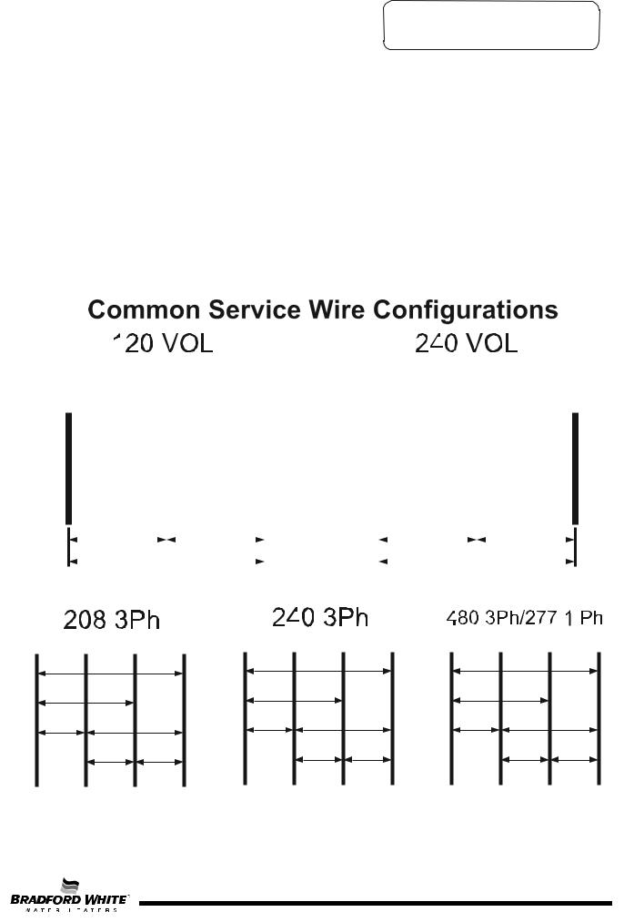
BLACK |
WHITE |
GREEN |
BLACK |
RED |
GREEN |
Grounded |
|||||
Ungrounded |
(Neutral) |
Grounding |
Ungrounded |
Ungrounded |
Grounding |
|
120 |
|
|
|
|
|
|
0 |
|
|
|
|
|
|
240 |
|
|
|
|
|
|
|
120 |
|
|
|
|
|
|
|
|
|
|
|
|
|
|
|
|
|
|
|
|
|
|
||||
|
|
|
|
|
|
|
|
|
|
|
|
|
|
|
|
|
|
|
|
|
||||
|
|
|
|
|
|
|
|
|
|
|
|
|
|
|
|
|
|
|
|
|
||||
|
|
|
|
|
|
|
|
|
|
|
|
|
|
|
|
|
|
|
|
|
||||
|
|
120 |
|
|
|
|
|
120 |
|
|
||||||||||||||
|
|
|
|
|
|
|
|
|
|
|
|
|
|
|
|
|
||||||||
|
|
|
|
|
|
|
|
|
|
|
|
|
|
|
|
|
|
|
|
|
|
|
|
|
|
|
|
|
|
|
|
|
|
|
|
|
|
|
|
|
|
|
|
|
|
|
|
|
|
|
|
|
|
|
|
|
|
|
|
|
|
|
|
|
|
|
|
|
|
|
|
|
|
|
|
|
|
|
|
|
|
|
|
|
|
|
|
|
|
|
|
|
|
|
|
|
|
|
|
Neutral |
A |
B |
C |
|
120 |
|
|
120 |
|
|
|
120 |
|
|
208 |
|
208 |
|
208 |
RED BLACK RED
Neutral |
A |
|
B |
C |
Neutral |
A |
|
B |
C |
|
|
120 |
|
|
|
|
277 |
|
|
120 |
|
|
|
277 |
|
|
|
||
120 |
|
|
240 |
|
277 |
|
|
480 |
|
|
|
240 |
240 |
|
|
|
480 |
480 |
|
|
RED |
BLACK |
RED |
|
RED |
BLACK |
RED |
||
Page 3
3
GENERAL INFORMATION
Wattage Limitations at Various Voltages
Residential Electric Upright RE2 & RE3 Series (Non-Simultaneous Operation)
Residential High Efficiency Upright RE2 Series (Non-Simultaneous Operation)
Residential Electric Lowboy RE2 Series (Non-Simultaneous Operation)
Maximum |
Element |
Voltage |
Wattage |
Upper/Lower |
|
3,000 |
3,000/3,000 |
120 |
|
|
|
6,000 |
6,000/6,000 |
208, 240 |
|
|
|
6,000 |
6,000/6,000 |
277, 480 |
|
|
|
Residential Electric Upright RE2 & RE3 Series (Simultaneous Operation)
Residential High Efficiency Upright RE2 Series (Simultaneous Operation)
Residential Electric Lowboy RE2 Series (Simultaneous Operation)
Light Duty Commercial Electric LE Series (Non-Simultaneous Operation)
Light Duty Commercial Electric LE Series (Simultaneous Operation)
Maximum |
Element |
Voltage |
Wattage |
Upper/Lower |
|
3,000 |
1,500/1,500 |
120 |
|
|
|
10,000 |
5,000/5,000 |
208 |
|
|
|
11,000 |
5,500/5,500 |
240 |
|
|
|
12,000 |
6,000/6,000 |
277, 480 |
|
|
|
Residential Electric Utility Series (Single Element Operation)
Light Duty Utility Series (Single Element Operation)
Maximum |
Single |
Voltage |
Wattage |
Element |
|
3,000 |
3,000 |
120 |
|
|
|
6,000 |
6,000 |
208, 240 |
|
|
|
6,000 |
6,000 |
277 |
|
|
|
6,000 |
6,000 |
480 |
|
|
|
Page 4
4
GENERAL INFORMATION
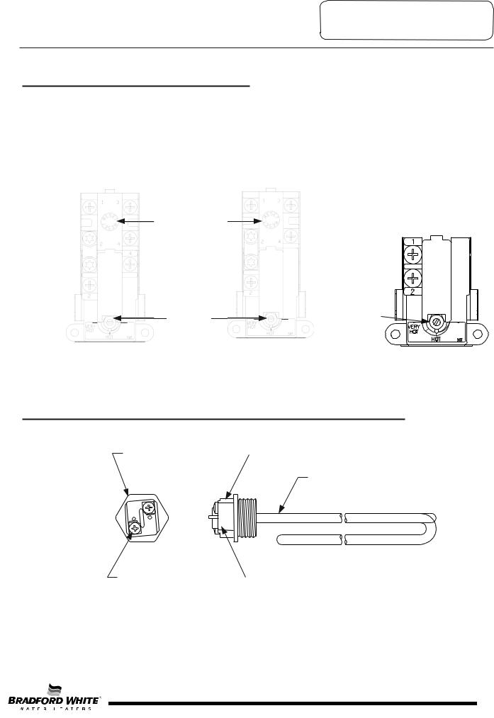
Surface Mounted Thermostats
Surface mounted thermostats are mounted into a bracket which holds the thermostat against the side of the tank. Surface mounted thermostats respond to tank surface temperatures to sense a call for heat, set point temperature settings and high limit (ECO) activation. It is important that the entire back surface of the thermostat is in full contact or flush with the tank. Improperly mounted thermostat will lead to improper water heater operation.
Manual
 ECO (high limit)
Reset button
Temperature |
|
Temperature |
control Dial |
|
control Dial |
Surface Mount |
Surface Mount |
Surface Mount |
Combination Thermostat/ |
Combination Thermostat/ |
Thermostat |
ECO (high limit) |
ECO (high limit) |
59T Series |
59T/66T Series |
59T/66T Series |
|
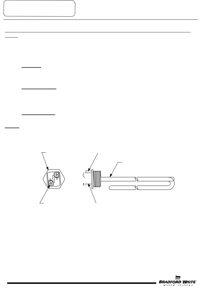
Direct Immersion “Screw-in” Type Heating Element
1-½ Hex |
|
Terminal Block |
Screw-in Flange |
|
|
|
|
Zinc Plated Copper or
Incoloy Sheath
Terminal Block |
|
Element Rating Ink Stamped |
Screw |
|
on side of Terminal Block. |
|
|
Page 5
5
SEQUENCE OF OPERATION
Residential and light duty commercial electric water heaters are designed to operate using several different operating modes. The common modes and sequence of operation are as follows:
1.Single Element Operation.
2.Double Element Non-Simultaneous Operation (single phase).
3.Double Element Non-Simultaneous Operation (3 phase).
4.Double Element Simultaneous Operation (single phase).
5.Double Element Simultaneous Operation (3 phase).
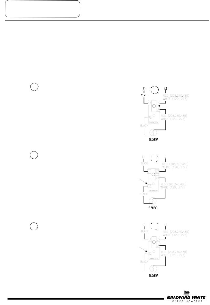
Sequence of Operation- Single Element Operation.
1Line voltage is applied across terminals L1 & L3 of the thermostat. ECO is closed, so there is voltage at terminal L4 and to one side of the element.
2Tank is cold therefore thermostat
is closed at terminal T2 (calling for heat). This completes the circuit and allows current to flow through the element.
1
ECO
Closed
2
Thermostat closed at terminal T2
3When the thermostat is satisfied, it opens at terminal T2 interrupting current flow through the element. System is now in stand-by mode, waiting for the next call for heat.
3
Thermostat opens at terminal T2
Page 6
6

SEQUENCE OF OPERATION
Non-Simultaneousand Simultaneous Operation
Double element electric water heaters are designed to operate in either Non-Simultaneous or Simultaneous mode.
Non-Simultaneous Mode: Allows only one heating element to operate at a time. For example, when the tank is cold, the upper element is energized first, heating the top of the tank. Only when the upper thermostat is satisfied, the upper element is de-energized and power is directed to the lower thermostat, energizing the lower element and heating the bottom portion of the tank until the lower thermostat is satisfied. As hot water is drawn off the tank, it is replaced with cold water delivered through the diptube to the bottom of the tank. When the tank cools at the lower thermostat level, the lower thermostat will call for heat, energizing the lower element. If enough hot water is drawn from the tank, the top portion of the tank cools and the upper thermostat will call for heat, de-energizing the lower element and allowing only the top element to energize until the upper thermostat is satisfied.
Simultaneous mode: allows both heating elements to operate at the same time. That is, if either thermostat (upper or lower) is calling for heat, the corresponding heating element is energized independent of the other.
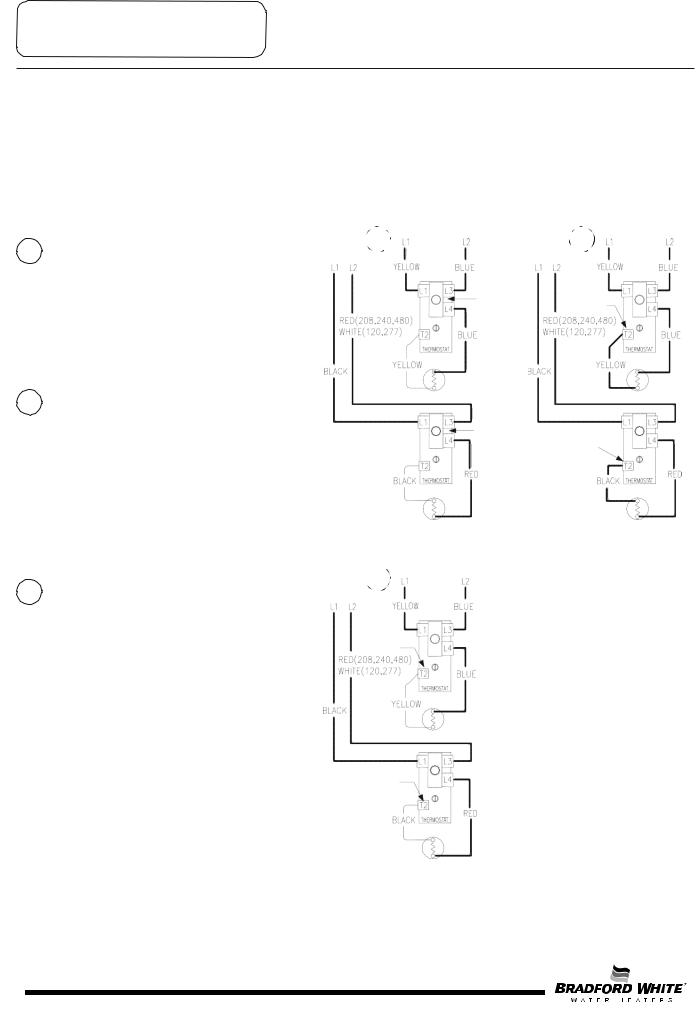
Sequence of Operation- Double Element, Non-Simultaneous Operation, Single Phase.
1Line voltage is applied across terminals L1 & L3 of the upper thermostat. ECO is closed, so there is voltage at terminal L4 and to one side of the upper and lower elements.
2Tank is cold. Therefore, the thermostats
are closed at terminals T2 & 2 (calling for heat). The circuit is complete through the upper thermostat only, allowing current to flow through upper element.
3When the upper thermostat is satisfied, it opens at terminal T2, interrupting current flow through the upper element. Terminal T4 closes, allowing voltage to pass to terminal 1 of the lower thermostat. This completes the circuit through the lower thermostat and allows current flow through the lower element.
4When the lower thermostat is satisfied, it opens at terminal 2, interrupting current flow through lower element. The system is now in stand-by mode waiting for the next call for heat.
1 |
2 |
ECO |
Thermostat closed |
Closed |
at terminal T2 |
Upper |
Upper |
T’stat |
T’stat |
Upper |
Upper |
Element |
Element |
|
Thermostat closed |
|
at terminal 2 |
Lower |
Lower |
T’stat |
T’stat |
Lower
Element Lower
Element
5 |
The lower thermostat/element |
|
|
combination will generally |
|
|
cycle on and off more often |
|
|
than the upper. In some cases, |
|
|
such as a cold tank or in high |
|
|
demand periods, the upper |
|
|
thermostat will call for heat |
|
|
(opening at terminal |
Thermostat closed |
T4 and closing at |
at terminal T4 |
|
terminal T2) prior to the lower thermostat being satisfied. This will interrupt current flow through the lower thermostat and element and allow current to flow through the upper element only. When the upper thermostat is satisfied, it resumes operation as described in sequence #3 above.
3 |
4 |
5 |
|
|
|||
|
|
Thermostat closed |
|
|
|
at terminal T2 |
|
Upper |
Upper |
Upper |
|
T’stat |
|||
T’stat |
T’stat |
||
|
|||
Upper |
Upper |
Upper |
|
Element |
Element |
Element |
|
Thermostat open |
|
Thermostat closed |
|
between terminals |
|
between terminals |
|
1 and 2 |
|
1 and 2 |
|
Lower |
Lower |
Lower |
|
T’stat |
|||
T’stat |
T’stat |
||
|
|||
Lower |
Lower |
Lower |
|
Element |
Element |
Element |
Page 7
7
SEQUENCE OF OPERATION
A 4 wire, double element heater wired for simultaneous operation is essentially two single element systems operating independently. The heaters are wired internally with two independent circuits, one circuit for each thermostat/element combination. When installed using a two wire service, the blue and red (or white) wires will be connected together, likewise black and yellow wires will be connected together.
Sequence of Operation- Double Element, Simultaneous Operation, Single Phase, 4 wire service installation.
1Line voltage from circuit one is applied across terminals L1 & L3 of the lower thermostat. Likewise, line voltage from circuit two is applied across terminals L1 & L3 of the upper thermostat. ECO in both upper and lower thermostat is closed, so there is voltage at terminal L4 of each thermostat and to one side of the upper and lower elements.
2Tank is cold therefore both thermostats are closed at terminal T2 (calling for heat). This completes the circuit through the thermostats and allows current to flow through the elements.
3When either thermostat is satisfied, it will open at terminal T2, interrupting current flow through the corresponding element. As both thermostats satisfy, the system will be in stand-by mode waiting for the next call for heat. Thermostats will operate independent of each other.
1 |
Circuit two |
|
2 |
Circuit two |
|
|
|
||
Circuit one |
|
|
Circuit one |
|
|
|
ECO |
Thermostat closed |
|
|
|
Closed |
|
|
|
|
at terminal T2 |
|
|
|
|
|
|
ECO
Closed
Thermostat closed at terminal T2
3 |
Circuit two |
|
Circuit one
Thermostat open at terminal T2
Thermostat open at terminal T2
Page 8
8
SEQUENCE OF OPERATION
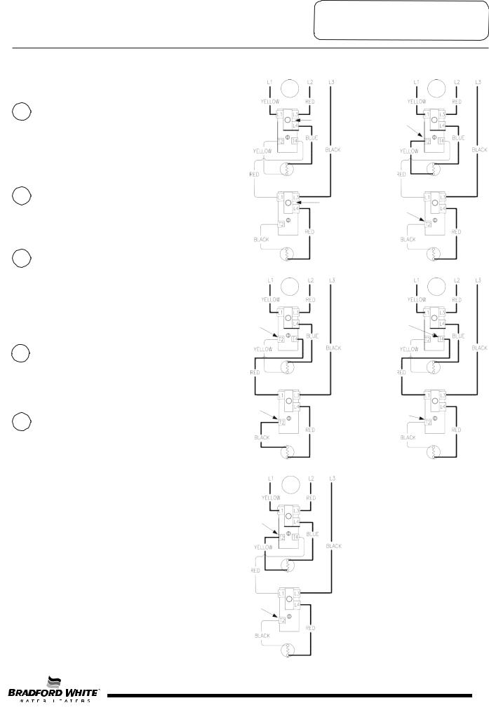
Sequence of Operation- Double Element, Non-Simultaneous Operation, 3 Phase.
1Line voltage is applied across terminals L1 & L3 of upper thermostat. Likewise, Line voltage is applied to terminal L3 of lower thermostat. ECO in both upper & lower thermostat is closed, so there is voltage at terminal L4 of both thermostats and to one side of both upper & lower elements.
2Tank is cold therefore both thermostats are closed at terminal T2 (calling for heat). The circuit is complete through the upper thermostat only allowing current to flow through the upper element.
3When the upper thermostat is satisfied, it opens at terminal T2 interrupting current flow through upper element, and closes at terminal T4 allowing voltage to pass to terminal L1 of lower thermostat. This completes the circuit through the lower thermostat allowing current flow through lower element.
4When the lower thermostat is satisfied, it opens at terminal T2 interrupting the current flow through the lower element. The system is now in stand-by mode waiting for the next call for heat.
5The lower thermostat/element combination will generally cycle on and off more often than the upper. In some cases, such as a cold tank or in high demand periods, the upper thermostat will call for heat (opening at terminal T4 and closing at terminal T2) prior to the lower thermostat being satisfied. This will interrupt current flow through the lower thermostat and element and allow current to flow through the upper element only. When the upper thermostat is satisfied, it resumes operation as described in sequence #3 above.
1
ECO
Closed
ECO
Closed
3
Thermostat closed at terminal T4
Thermostat closed at terminal T2
5
Thermostat closed at terminal T2
2
Thermostat closed at terminal T2
Thermostat closed at terminal T2
4
Thermostat closed at terminal T4
Thermostat open at terminal T2
Thermostat closed at terminal T2
Page 9
9
SEQUENCE OF OPERATION
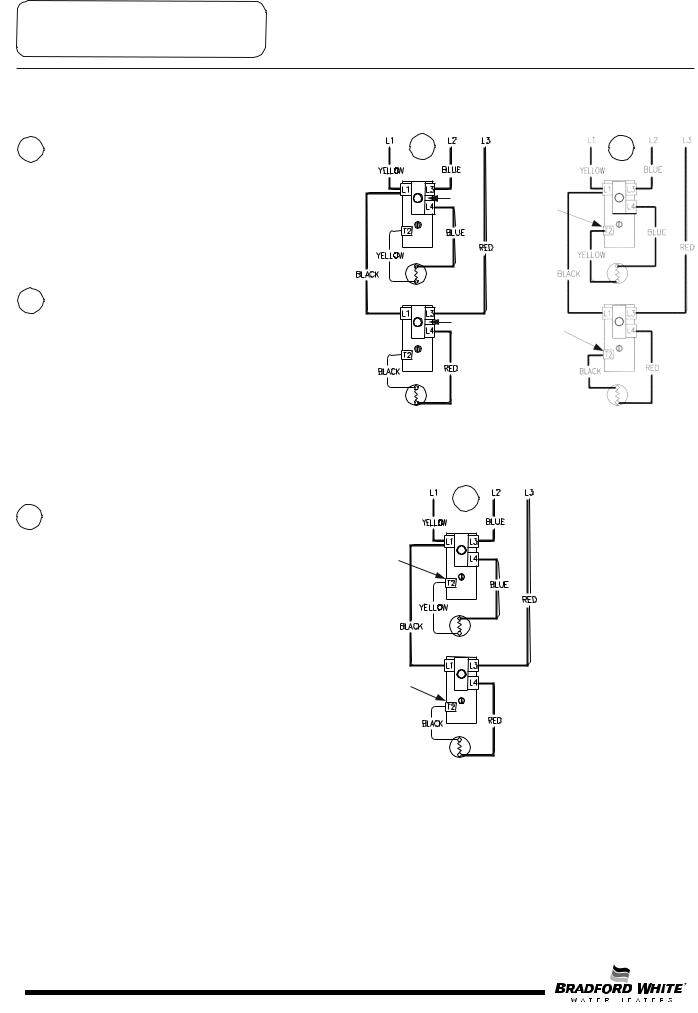
Sequence of Operation- Double Element, Simultaneous Operation, 3 Phase.
1Line voltage is applied across terminals L1 & L3 of upper thermostat. Line voltage also extends to terminal L1 of lower thermostat. Also, line voltage is applied to terminal L3 of lower thermostat. ECO in both upper & lower thermostat is closed, so there is voltage at terminal L4 of both thermostats and to one side of both upper & lower elements.
1 |
2 |
ECO |
|
Closed |
Thermostat closed |
|
at terminal T2 |
2Tank is cold therefore both thermostats are closed at terminal T2 (calling for heat). This completes the circuit through the thermostats and allows current to flow through the elements.
ECO |
|
Closed |
at terminal T2 |
|
3When either thermostat is satisfied, it will open at terminal T2, interrupting current flow through the corresponding element. As both thermostats satisfy, the system will be in stand-by mode waiting for the next call for heat. Thermostats will operate independent of the other.
3
Thermostat open at terminal T2
Thermostat open at terminal T2
Page 10
10

SEQUENCE OF OPERATION
Some electric utility companies will offer discounts for using electricity during “Off Peak” Times of the day. The system allows the use of an “Off Peak” meter, which interrupts power to the lower element during high power demand periods.
Sequence of Operation- Double Element, Non-Simultaneous Operation, Single Phase, Off Peak.
1Line voltage is applied across terminals
L1 & L3 of the upper thermostat. Line voltage from off peak meter is supplied to terminal L1 of lower thermostat. ECO in the upper thermostat is closed, so there is voltage at terminal L4 of upper thermostat and to one side of the upper element.
Tank is cold therefore both thermostats
2are closed at terminal T2 (calling for heat). The circuit is complete through the upper thermostat only, allowing current to flow through upper element.
3When upper thermostat is satisfied, it opens at terminal T2 interrupting current flow through upper element, and closes at terminal T4 allowing voltage to pass to one side of the lower element. This completes the circuit through the lower thermostat and off peak meter allowing current flow through lower element.
4When the lower thermostat is satisfied, it opens at terminal T2 interrupting current flow through lower element. The system is now in stand-by mode waiting for the next call for heat
5During peak power demand periods as determined by the local utility, the off peak meter will interrupt power to terminal L1 of lower thermostat. Only the top thermostat/element combination is allowed to operate during this period.
From Off
Peak
Meter
1 |
|
2 |
|
ECO |
Thermostat closed |
|
Closed |
|
|
at terminal T2 |
|
|
|
Thermostat closed at terminal T2
From |
3 |
4 |
5 |
Off Peak |
|
|
Off Peak |
Meter |
|
|
Power interrupted |
Thermostat closed |
|
|
Thermostat closed |
at terminal T4 |
|
|
at terminal T2 |
Thermostat closed |
Thermostat open |
at terminal T2 |
at terminal T2 |
Page 11
11
TROUBLESHOOTING
Most common cause for improper electric water heater operation can be linked to heating element
failure.
When troubleshooting an electric water heater with the incidence of “No Hot Water” or “Insufficient Amount of Hot Water,” It’s always a good idea to check the heating elements first by following the procedure on page 15.
Common Heating Element Failures:
1.Dry Firing. Element may be partially submerged in water or most likely, completely exposed with no water in tank. In some cases, sediment or lime build up around an element can eventually cause an air pocket, and within seconds, result in a dry fired element. At this point the element becomes inoperative. When element replacement is required, be sure the tank is full of water prior to energizing the water heater.
2.Grounded Element. An element with a short circuit to ground will in most cases cause the circuit breaker in the service panel to open or shut off. In some cases, there may not be enough current draw for the circuit breaker to open. This will allow the heating element to be in continuous operation resulting in over heated water, limited only by the ECO or Energy Cut Out. Repeated actuation of the ECO is
usually the result of a grounded element.
3.Sediment build up. Slow hot water recovery can usually be traced back to sediment or lime build up around heating element. Sediment build up can also over time cause a dry fired element.
Figure 1, below shows a common “Screw-In” type heating element identifying certain features commonly referred to throughout this manual.
1-½ Hex |
|
Terminal Block |
Screw-in Flange |
|
|
|
|
Zinc Plated Copper or
Incoloy Sheath
|
|
|
|
0642 |
4500W 240V |
RC02404524 |
|
|
|
|
|
||||
|
|
|
|
||||
|
|
|
|
||||
|
|
|
|
|
|
|
|
|
|
|
|
|
|
|
|
|
|
|
|
|
|
|
|
Terminal Block |
|
|
|
|
Element Rating Ink Stamped |
|||
Screw |
|
|
|
|
||||
|
|
|
|
on side of Terminal Block. |
||||
|
|
Figure 1 |
||||||
|
Typical Direct |
|
|
|
|
|||
|
Immersion “Screw-In” |
|||||||
|
|
Type Heating Element |
|
|
||||
Page 12
12
 Loading...