


Bradford White D-80T-199-3N, D-100T-250-3NA, D-100S-199-3N, D-80T-180-3N, D-38T-155-3N+ User Manual
...COMMERCIAL 24 VOLT FLUE DAMPER SERIES WATER HEATER WITH HONEYWELL
INTEGRATED CONTRO
Gas Water Heaters
SERVICE
MANUAL
Troubleshooting Guide and Instructions for Service
(To be performed ONLY by qualified service providers)
Models Covered
by This Manual:
For The Bradford White “D” Series Models: D38T155 D75T(125,160,300) D65T(370,399) D80T(180,199,250) D80T(425,505) D100T(199,250) D80L(399,450,505) D100L(199,250,270,300) D100S(199,250)
Manual 47985A REV 08/18 |
Save this manual for future reference |

Table of Contents
|
Page |
Service Procedure |
||
Introduction |
4 |
|
|
- - - |
Tools Required for Service |
4 |
|
- - - |
|
Sequence of Operation |
6 |
|
- - - |
|
Troubleshooting |
7 |
|
- - - |
|
Thermostat Circuit Testing |
24 |
|
|
D24-I |
Pilot Operation Testing |
27 |
|
|
D24-II |
Main Burner Operation Testing |
30 |
|
|
D24-III |
Main Burner & Pilot Removal & Inspection |
32 |
|
|
D24-IV |
Flue Baffle Removal & Inspection |
35 |
|
|
D24-V |
Anode Removal & Inspection |
36 |
|
|
D24-VI |
Generic Parts List |
38 |
|
- - - |
|
Glossary of Terms |
41 |
|
- - - |
|
Notes |
41 |
|
- - - |
|
Page 2
2

FEATURES OF HONEYWELL INTEGRATED CONTROLS SYSTEM
Attractive digital water heater display on control panel for setting and displaying the temperature setpoint. Pressing temperature up and down buttons changes the temperature setpoint. Temperature format may be displayed in degrees F or degrees C.
Single control board with plug in wiring controls temperature, ignition, and flue damper operation.
Reduced number of parts for servicing and wiring.
Plug in wiring reduces chance of miswiring.
Water heater display will show diagnostic codes in the event the water heater needs servicing. Aids in diagnosing and servicing the water heater.
Water heater display can show up to 10 previous error codes in the service mode to further aid in servicing the water heater.
Page 3
3

Introduction
It is intended for this manual to be used by qualified service personnel for the primary purpose of troubleshooting analysis and repair of the Bradford White 24 Volt Flue Damper Series Water Heater. Understanding the sequence of operation section of this manual will contribute greatly to troubleshooting this product.
Troubleshooting begins by noting the error code, if any, on the water heater control display and finding the section in this service manual for diagnosing the problem for this error code. This step by step procedure beginning on page 5 will direct the service provider to a series of test procedures to determine root cause of failure.
Contact Technical support immediately if diagnosis is not determined using the methods described in this service manual.
Tools Required for Service |
|||
|
|
|
|
Manometer: |
|
Two types available, a liquid “U” tube type or a digital (magna-helic) |
|
|
|
type. This device is used to measure gas and/or air pressures and |
|
|
|
vacuum. |
|
Multi-Meter: |
A digital type is strongly recommended. This device is used to measure |
||
|
|
electrical values. The meter you select must have the capability to |
|
|
|
measure volts AC, volts DC, Amps, micro-amps and ohms. |
|
Thermometer: |
Used to measure water temperature. An accurate thermometer is |
||
|
|
recommended. |
|
Water Pressure Gage: |
Used to measure water supply pressure. Also used to determine tank |
||
|
|
pressure by adapting to the drain valve of the heater. |
|
Jumper Leads: |
A length of wire (12" min.) with alligator clip at both ends. |
||
Various Hand Tools: |
Pipe wrench, channel locks, open end wrench set, 12" crescent wrench, |
||
|
|
Allen wrench set, torx bit set, screw drivers (common & phillips), long |
|
|
|
reach (12") magnetic tip phillips head screw driver #2 tip, ¼" nut driver, |
|
pliers (common & needle nose), socket set including a 1-1/16 deep well socket, wire cutters, wire strippers, wire crimpers, torpedo level, small shop vac, step ladder, and flashlight.
Page 4
4

Specifications
Power Supply |
Dedicated 120 VAC, 60 Hz., 15 A |
|
|
Current Draw |
Less than 5 Amps. |
|
|
Gas Supply Connection |
1" NPT connection to gas valve for 370,000 Btu/hr. and over for natural gas, |
|
¾" NPT for rest. Schedule 40 black iron pipe recommended. |
|
|
Approved Gas Type |
Natural or Propane. Gas supply must match the gas type listed on the water |
|
heater rating label. |
|
|
Gas Pressure (Nat. & L.P.) |
Manifold Pressure: 4.5" w.c. natural gas, 10.0" w.c. L.P. Gas Supply |
|
Pressure: At least 1" above manifold pressure with water heater operating, |
|
14" w.c. maximum. |
|
|
Venting System |
Atmospherically Vented, Type B venting system or approved chimney. Follow |
|
current National Fuel Gas Code requirements or in Canada, the Natural Gas |
|
and Propane Installation Code. |
|
|
Minimum Clearance for Servicing |
24" Front Clearance, 20" Top, 6" Sides. |
|
|
Maximum Water Supply Pressure |
150 PSI. |
|
|
Thermostat Sensor(s) |
Redundant thermister with 11,900 + or - 0.5% ohms resistance at 70 deg. F. |
|
Sensor inside well for lower sensor. Some models use an additional upper |
|
sensor (w/o well) with same resistance values. |
|
|
Control Board |
Honeywell Integrated Control Board for Temperature Control, Flue Damper, |
|
and Ignition Control Functions. Operates on 24 volts AC current from |
|
transformer. Some models use single sensor boards, others use two |
|
sensors. |
|
|
Control Display |
Honeywell LCD Control Display with Temperature Setpoint, Format, and Error |
|
Code Display in User Mode, Diagnostic Functions in Service Mode. |
|
Communicates with Control Board. |
|
|
Transformer |
120 VAC Primary, 24 VAC Secondary, 40 VA. |
|
|
Pilot |
Intermittent Pilot with Spark Electrode and Flame Sensor monitored by Control |
|
Board. |
|
|
Flue Damper |
24 VAC, 60 Hz., 80 Ma. |
|
|
Page 5
5
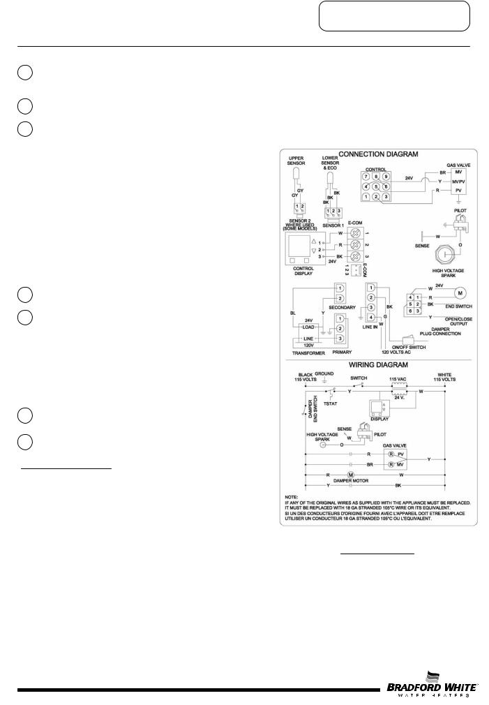
Sequence of Operation
1
2
3
4
5
7
8
Thermostat calls for heat.
The control board sends 24 volts from damper terminal #2 on the control plug to the flue damper.
Flue damper begins to rotate open. Once the flue damper is fully open, the damper end switch closes and 24 volts is allowed to continue through damper to damper pin terminal #5.
Trial for ignition (three 90 second ignition trials, with 65 second pauses between trials).
Control Board simultaneously sends:
1.24 volts from control pin terminal #8, to “MV/PV” terminal of gas valve (common terminal).
2.24 volts from control pin terminal #2, to “PV” terminal of gas valve to establish
gas flow at pilot.
3.Low current high voltage from “spark” terminal, to generate spark at the pilot and ignite pilot gas flow.
4.Pilot flame proving signal (measured in micro-amps). from the “sense” terminal, to prove pilot flame.
Once pilot flame is proven, sparking will stop.
Once sparking stops, 24 volts is sent from control pin terminal #5 on control board, to “MV” terminal on gas valve to establish main burner gas flow. Main burners ignite from the pilot flame.
The control board constantly monitors pilot flame through the flame sensor rod. If pilot flame is lost, pilot and main burners are shut down. After a 65 second inter-purge period, the control will attempt to re-light the pilot beginning at sequence 3 above.
Main burner fires until the thermostat is satisfied. The control board interrupts 24 volts through the damper and the gas valve circuit. Pilot and main burners are turned off.
Flue damper rotates to the closed position.
LOCKOUT CONDITION
Control board will go into “Soft Lockout” if the pilot cannot be lit after 3 ignition trials. The water heater display indicates a lockout condition by showing an error code number (62 or 63) with “Service Needed” in the display window. Refer to error codes in the diagnostic section of this Service Manual. In a “Soft Lockout” condition, the control will wait for 60 minutes and then make 3 more attempts to light the pilot and establish the main burners.
Soft lockout reset is accomplished by depressing the lower right WIRING DIAGRAM button under “Reset” for 3 seconds.
If the water heater should reach 200 degrees F, then the high limit control will shut off the burners and the water heater will go into a “Hard Lockout”. Error code 65 will be shown in the water heater display. The control can only be reset in the “service mode”, which is detailed in the next section of this Service Manual.
Page 6
6

Troubleshooting
CAUTION |
Use Caution Not to Damage Connectors when making Voltage Measurements or Jumping Terminals |
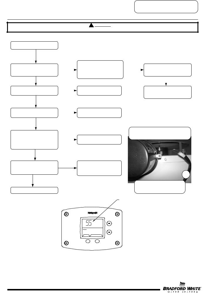
Water Heater Fault: Water heater does not operate
Display Error Code: Water heater display does not operate - blank display
Check main power supply to water |
1 |
heater - fuse, circuit breaker, plug receptacle, line cord or wiring to water heater.
Check to make sure switch on top of control panel is in the ON position
Checking line voltage to board. Pins to black and white wires.
Verify Primary and Secondary
voltage at the control board.
If there is not 24 volts at Secondary pins on the control board, check transformer. Replace transformer or wire harness.
Voltage at primary pins 1&3 (white and black wires) should be 110-120. If not,  check Line In pins 1&4. Check line cord
with ohmeter. Replace line cord if defective.
3
2
Checking primary voltage to transformer from board. Pins to black and white wires.
4
Does water heater display operate? Does damper begin to open?
Increase thermostat setting if tank is warm and make sure the control display status reads “Heating”.
Y
See next page
Checking secondary voltage from transformer. Pins to blue and yellow wires.
N |
Check wire connections of |
|
|
|
board to display. See |
|
|
|
illustration. |
5
Checking transformer voltage, front terminals are 24 volts, rear terminals are 120 volts.
With the control cover tilted down, measure the voltage between red and black wire pin connections to display. Voltage should be 24 volts AC measured at the back of the Control Display.
If no voltage at Display, check wire harnesses and voltage at E-com screw terminals (see photo 5).
Replace display if voltage is present at display pin terminals. Replace control board if no voltage is present at E- com terminals (1&3, white-black wires and 1&2, white-red wires) to display.
Page 7
7
Troubleshooting
CAUTION |
Use Caution Not to Damage Connectors when making Voltage Measurements or Jumping Terminals |
From previous page
Does damper blade move to the full open position?
Y
Is there pilot flame?
Y
Does Main Burner operate?
Y
Does burner continue until thermostat set point is reached? See setting display in Service Mode and displaying temperature sensors.
Y
Does the flue damper rotate to the fully closed position?
Y
System okay
|
Error code #55 on display. |
|
|
|
N |
Remove damper from heater and |
|
Does water heater begin to |
|
|
jump black & yellow wires of |
|
||
|
|
operate? |
||
|
heater harness. Refer to photo on |
|
||
|
|
|
|
|
|
this page. |
|
|
Y |
|
|
|
||
|
|
|
|
|
N |
Error code #62 on display. See |
|
Check for debris limiting damper |
|
|
|
|||
|
“Pilot Will Not Light”. |
|
rotation. If no debris, replace |
|
|
|
|
damper. |
|
N |
Error code #62 on display. See |
|
|
|
|
|
|
|
|
|
“Pilot Lights, No Flame Signal” |
|
|
|
N |
Error code #63 on display. See |
|
|
|
“Main Burner Short Cycles”. |
Error code #56 on display.
N Check for debris limiting damper rotation. If no debris, replace
damper
Damper vane show in open position. If damper is closed, disconnect from harness and REMOVE damper from water heater.
6
Harness shown disconnected from damper with BLACK and YELLOW wires jumped.
Error Code Shown
in Water Heater Display
Status Service Needed
SELECT Lockout RESET
Example of error code shown on control display.
Page 8
8
Troubleshooting
Using Control Display for Servicing the
Water Heater
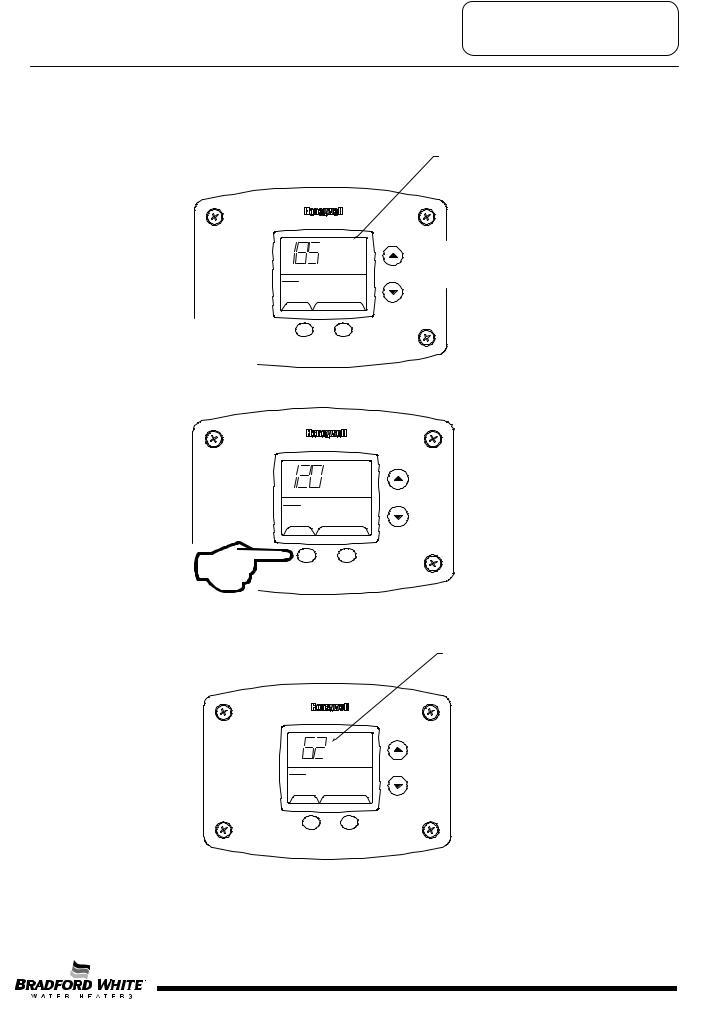
ACCESSING SERVICE MODE ON THE WATER HEATER DISPLAY (FOR SERVICE PERSONNEL ONLY)
The display has a “service mode” for changing the maximum setpoint and accessing information in aiding servicing of the water heater. This procedure is for service and installation personnel only. To enter the Service Mode, follow the steps illustrated below:
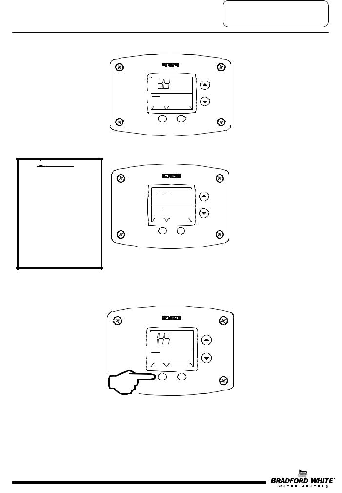
Step 1: Press “Select” and “Temperature Up” buttons together and hold for 3 seconds until “Max Setpoint” is shown in the display. "Max Setpoint”
next to Temperature Setpoint value.
Max
Setpoint
idle
Statu Operational s
SELECT |
SET |
Step 2: Pressing “Select” button |
to next mode |
°F Water
Temp
idle
Status Operational
SELECT |
SET |
The following is the sequence of modes available in “Service Mode” by pressing the “Select” button:
Error Code Number (Display/Reset). This is only shown if there is an operating error in the “User Mode”.
Error Code Shown
in Water Heater Display
Status Service Needed
SELECT Lockout RESET
Page 9
9
|
|
Troubleshooting |
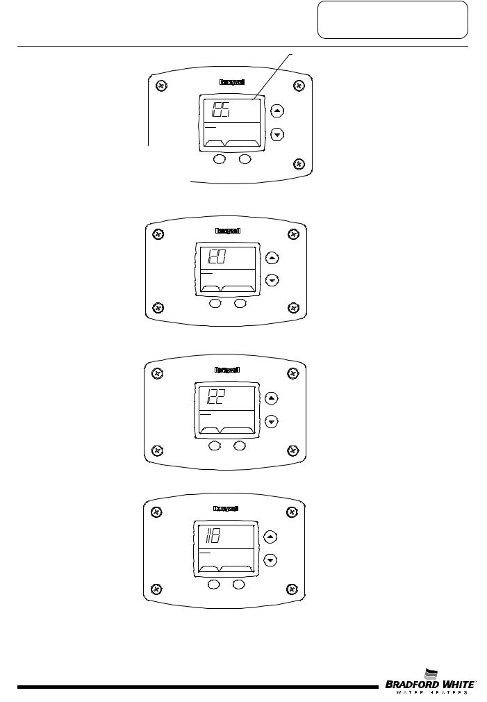
1. Max Setpoint (Display/Change) |
|
Max Setpoint value in |
|
|
Water Heater Display |
°F |
Max |
|
|
Setpoint |
|
idle |
|
|
Status Operational |
|
|
2a. Water Temperature Average (Displays&average ifSELECTthere are twoSET |
sensors - sensor temperature displayed if single |
|
sensor is used). |
|
|
°F Water Temp
idle
Status Operational
SELECT |
SET |
2b. Water Temperature - Upper Sensor (Displays if there is an upper sensor - some models)
°F
idle
Status Operational
Upper Sensor
SELECT SET
2c. Water Temperature - Lower Sensor (Displays if there are two sensors)
°F
idle
Status Operational
Lower Sensor
SELECT |
SET |
Page 10
10
Troubleshooting
3.Flame Current of Pilot Flame Sensor (Displays only in the Heating Cycle)
|
ȝA |
Heating |
Flame Current |
Status Operational |
|
SELECT |
SET |
4. Setpoint (Display/Change)
°F setpoint
idle
Status Operational
SELECT |
SET |
5.°F/°C (Display/Change)
°F °F/C° setpoint
idle
Status Operational
SELECT |
SET |
6.Differential (Display only - shows the differential of the thermostat)
°F Differential
idle
Status Operational
SELECT |
SET |
Page 11
11
Troubleshooting
7. Software Version (Display only)
Soft
idle
Status Operational
SELECT |
SET |
8. Error Code History (Displays if there are present error codes or up to 10 previous error codes). Water Heater Display will show a “--“ if there are no error codes.

 WARNING
Setting the water temperature to the maximum set point can result in scalding hot water delivered to the faucets. It is highly recommended that the maximum setpoint be adjusted to the lowest temperature possible for the needs of the installation. Make sure the water heater control display is not in a public area that can result in the temperature settings being improperly adjusted.
idle
Status Operational
SELECT |
SET |
To change the Maximum Setpoint Limit (Max Setpoint) for the temperature setpoint:
Step 1: In service mode press the “Select” button until “Max Setpoint” is displayed.
°F Max
Setpoint
idle
Status Operational
SELECT |
SET |
Page 12
12
Troubleshooting
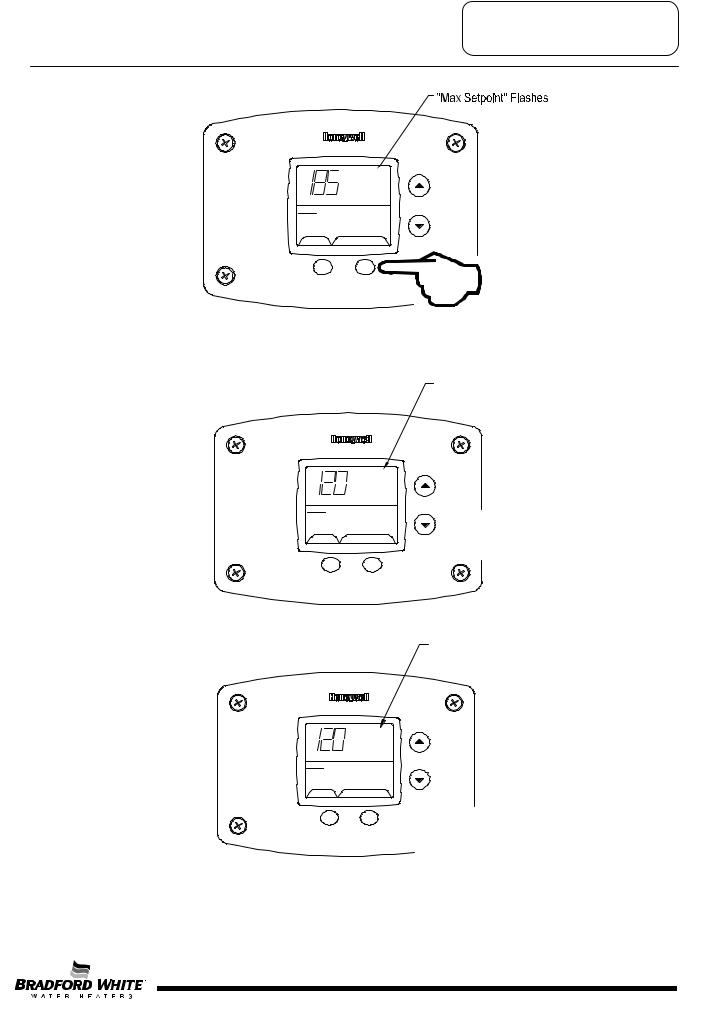
Step 2: Press “Set” button to enter setting mode. “Max Setpoint” will flash to indicate setting mode.
°F Max
Setpoint
idle
Status Operational
SELECT |
SET |
Step 3: Press the “UP” or “DOWN” buttons to change the maximum setpoint value. This will limit the maximum setpoint the user can select. Note: The maximum setpoint is approximately 180°F.
"Max Setpoint" continues to flash while making adjustments
°F |
Max |
|
|
Setpoint |
% |
idle |
|
|
Status Operational |
|
|
SELECT |
SET |
Step 4: Press “Set” button to confirm new “Max Setpoint” value and stop setting mode.
"Max Setpoint" stops flashing
°F Max
Setpoint
idle
Status Operational
SELECT %SET
Page 13
13
Troubleshooting
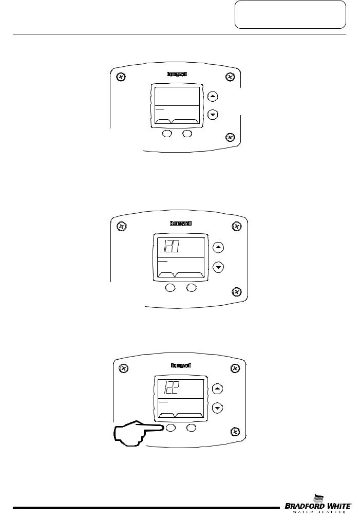
Step 5: 30 Seconds after the last button press, the Water Heater Display will go back to “User Mode”. It will read “Max Setpoint” without showing a temperature value if the temperature setpoint is at the maximum setting. The Water Heater Display can be set back to the “User Mode” immediately by pressing both the “Temperature Up” and “Select” buttons together for 3 seconds.
Max %
Setpoint
idle
Status Operational
&ExitingSELECTServiceSETMode
Display of Water Temperature:
Step 1: In Service Mode, Press the “Select” button until “Water Temp” is displayed in the upper right section of the water heater display. For water heaters using two temperature sensors in the tank, this will be the average reading between the two sensors. For water heaters using a single sensor, this is the reading for the sensor.
°F Water
Temp
idle
Status Operational
&SELECT SET
Step 2: For water heaters using two temperature sensors, pressing the “Select” button again displays the Upper Sensor temperature reading. “Upper Sensor” will be displayed in the lower right side of the status window of the water heater display.
°F
idle
Status Operational
Upper Sensor
SELECT |
SET |
Page 14
14
 Loading...