


Bradford-White M1XR403S-FBN, MI403S-F-BN, MI404T-F-BN, M450S-F-BN, MI50L-F-BN User Manual
...Flammable Vapor Ignition Resistant Water Heater
SERVICE
MANUAL
Troubleshooting Guide and Instruction for Service
(To be performed ONLY by qualified service providers)
For the Bradford White
Defender Safety System™
Models:
MI30T*F(BN,CX)2 |
M430T*F(BN,CX)2 |
MI30S*F(BN,CX)2 |
M4403S*F(BN,CX)2 |
MI303T*F(BN,CX)2 |
M4403T*F(BN,CX)2 |
MI40T*F(BN,CX)2 |
M450S*F(BN,CX) |
MI403S*F(BN,CX)2 |
M1XR403S*F(BN,CX)2 |
MI404T*F(BN,CX)2 |
M1XR504T*F(BN,CX)2 |
MI503*F(BN,CX)2 |
M2XR504T*F(BN,CX)2 |
MI50L*F(BN,CX)2 |
M2C504T*F(BN,CX) |
MI504S*F(BN,CX)2 |
50T65F(BN,CX) |
|
(*) Denotes Warranty Years. |
Manual 44943A |
Save this manual for future reference |

Flammable Vapor Ignition Resistant Water Heater
Table of Contents
|
Page |
Service Procedure |
Introduction |
3 |
- - - |
Trouble shooting Chart |
4 |
- - - |
Inner Door Gasket Removal, Inspection, Replacement and Installation |
5 |
RG-I |
Thermocouple Testing and Replacement |
8 |
RG-II |
Pilot Assembly Inspection Cleaning and Replacement |
10 |
RG-III |
Piezo Igniter and Electrode Testing |
11 |
RG-IV |
Combination Thermostat/Gas Valve Testing and Replacement |
12 |
RG-V |
Burner Operation Inspection, Adjustment, Cleaning and Replacement |
17 |
RG-VI |
Resettable Thermal Switch Testing and Replacement |
20 |
RG-VII |
ScreenLok Flame Arrestor Cleaning |
22 |
RG-VIII |
Dip Tube and Anode Inspection and Replacement |
23 |
RG-IX |
Generic Parts List |
25 |
- - - |
2

Introduction
The Bradford White DEFENDER Safety System™
The Bradford White DEFENDER Safety SystemTM was designed to resist the ignition of flammable vapors that can occur outside of the water heater. Use and installation are nearly identical to previous versions of atmospherically fired and vented water heaters. A number of exclusive design features are incorporated in the system that will require additional knowledge on the part of the qualified service provider. The following information will instruct service professionals on the function, proper diagnosis and repair of water heaters employing the Bradford White DEFENDER Safety System .
How the Safety System Works™
During normal operation, air for combustion is drawn into the water heater through the openings in the jacket. This air travels down and around the combustion chamber and enters through holes in the very bottom of the corrosion-resistant combustion chamber. The air then travels up through the oriented flame arrestor plate louvers, where the velocity of the air is increased and its direction altered. The air then mixes in a normal manner with supplied gas and is efficiently combusted, producing very low NOx emissions. In the unlikely event trace amounts of flammable vapors are present in the air flowing into the combustion chamber, the vapors are harmlessly ignited by the burner / pilot flame. If flammable vapors are in sufficient quantity to prevent normal combustion, the burner / pilot flame is shut down. Should the flammable vapors continue to burn, the flame arrestor plate prevents the flames from traveling backwards and igniting vapors outside of the combustion chamber. The calibrated, multipurpose thermal switch recognizes this and shuts down the pilot and main burner. This switch also deactivates the burner and pilot in the unlikely event of restricted airflow caused by severe lint, dust or oil accumulation on the arrestor plate. If accumulation occurs, the ScreenLok flame arrestor can be easily cleaned and when the inner door is properly secured the unit can then be placed in operation. A cleaning procedure is included in this service manual.
3

Troubleshooting Chart
Flammable Vapor Ignition Resistant Water Heaters
SYMPTOM |
|
PROBABLE CAUSE |
CORRECTIVE ACTION |
SERVICE |
|
|
PROCEDURE |
||||
|
|
|
|
||
|
|
|
|
||
|
1. No incoming gas or too |
1. Turn on gas supply and/or check line pressure. |
1. See Service Procedure |
||
|
|
low gas pressure. |
RG-V, Page 12. |
||
|
|
2. Review lighting instruction. |
|||
|
2. |
Gas control knob set |
|
||
|
Set combination/thermostat gas valve to correct |
4. See Service Procedure |
|||
|
|
to wrong position. |
|||
|
|
position. |
|||
Pilot Will |
3. |
Pilot light button not being fully |
RG-III, Page 10. |
||
3. Review lighting instruction. Fully depress pilot |
|||||
Not Light |
|
depressed when attempting to |
lighting button. |
5. See Service Procedure |
|
|
light pilot. |
||||
|
4. Clean, repair or replace. |
||||
|
4. |
Pilot orifice or pilot tube is |
RG-III, Page 10. |
||
|
5. Verify correct electrode position. |
||||
|
|
obstructed or kinked. |
|
||
|
|
Replace pilot assembly. |
6. See Service Procedure |
||
|
5. |
Pilot electrode not sparking to pilot. |
|||
|
6. Replace Piezo igniter. |
||||
|
6. |
Piezo igniter not functioning. |
RG-IV, Page 11. |
||
|
|
||||
|
|
|
|
|
|
|
1. Poor thermocouple connection at |
1. Check connection at combination thermostat/gas |
|
||
|
valve. Proper tightness should be finger tight |
|
|||
|
|
combination thermostat/gas valve. |
plus 1/4 turn. |
|
|
|
2. |
Thermocouple not fully engaged in |
2. Inspect thermocouple to ensure that it is fully |
4. See Service Procedure |
|
Pilot will not |
|
pilot assembly bracket. |
engaged into pilot bracket. |
||
|
RG-II, Page 8. |
||||
3. |
Pilot flame is not fully enveloping the |
3. Adjust tip of thermocouple to be fully engulfed |
|||
stay lit when |
|
thermocouple “hot” junction. |
by pilot flame. |
5. See ServiceProcedure |
|
4. |
Weak or defective thermocouple. |
4. Check thermocouple and replace if necessary. |
|||
button is |
5. |
Open ECO on combination |
5. Check ECO continuity and replace combination |
RG-V, Page 13. |
|
released |
|
thermostat/gas valve. |
thermostat/gas valve if necessary. |
6. See Service Procedure |
|
6. |
Defective magnet in combination |
6. Check magnet operation and replace |
|||
|
RG-V, Page 13. |
||||
|
|
thermostat/gas valve. |
combination thermostat/gas valve if necessary. |
||
|
|
|
|||
|
7. Resettable thermal switch has |
7. Determine cause of switch activation. To reset, |
|
||
|
|
opened. |
depress button on resettable thermal switch |
|
|
|
|
|
located on inner door. |
|
|
|
|
|
|
||
|
1. Combination thermostat/gas valve |
|
2. See Installation |
||
|
|
set too low for desired water temp. |
1. Adjust temperature dial on combination |
||
Pilot will light |
|
& operation manual. |
|||
2. |
Combination thermostat/gas valve |
thermostat/gas valve. |
|||
but the main |
|
temperature is satisfied. |
2. Check temperature dial setting on combination |
3. See Service Procedure |
|
3. |
Insufficient gas supply or low gas |
thermostat/gas valve. |
|||
burner will |
|
pressure. |
3. Check gas supply and line pressure. |
RG-V, Page 12. |
|
4. |
|
||||
not come on |
Combination thermostat/gas valve |
4. Check combination thermostat/gas valve for |
4. See Service Procedure |
||
|
has wide differential or is out of |
proper operation, replace if necessary. |
|||
|
|
calibration. |
|
RG-V, Page 12. |
|
|
|
|
|
||
|
|
|
|
|
|
Pilot goes out |
|
|
1. Verify adequate combustion air is available to the |
|
|
periodically |
|
|
unit. Check and clear Jacket slot openings of any |
|
|
1. Insufficient combustion air supply. |
dirt, dust, restrictions or other obstructions. |
1. See Service Procedure |
|||
(after heating |
2. |
Incorrect, clogged vent system/ vent |
Inspect flame arrestor plate and clean with stiff |
RG-VIII, Page 22. |
|
cycles, once a |
|
terminal or location. |
bristled brush and/or vacuum to remove any |
|
|
3. |
Inconsistent gas supply or gas |
debris accumulation. |
3. See Service Procedure |
||
day, once a |
|
pressure. |
2. Check venting for proper sizing and proper |
RG-V, Page 12. |
|
|
|
operation |
|
||
week etc.) |
|
|
3. Check gas supply and line pressure. |
|
|
|
1. Combination thermostat/gas valve |
1. Check dial on combination thermostat/gas valve. |
|
||
|
|
set too low for desired water temp. |
2. Extremely cold water going into the heater will |
|
|
|
2. |
Cold inlet water temp. is very cold. |
decrease the amount of hot water produced. |
5. See Service Procedure |
|
Not enough |
3. |
High demand periods. |
It may be necessary to temper incoming water |
RG-V, Page 12 |
|
4. |
Incorrectly sized water heater for |
supply. |
|
||
hot water |
5. |
application. |
3. Adjust high demand usage. |
6. See Service Procedure |
|
|
Combination thermostat/gas valve is |
4. Contact Plumbing professional. |
RG-IX, Page 23 |
||
|
|
out of calibration/not functioning. |
5. Check combination thermostat/gas valve for |
|
|
|
6. |
Out of spec dip tube is diluting hot |
proper operation, replace if necessary. |
|
|
|
|
water with cold water. |
6. Inspect dip tube and replace if necessary. |
|
|
|
|
|
|
|
|
4
SERVICE PROCEDURE RG-I
Inner Door/Gasket Removal, Inspection
Replacement and Reinstallation
Inner Door Removal Procedure
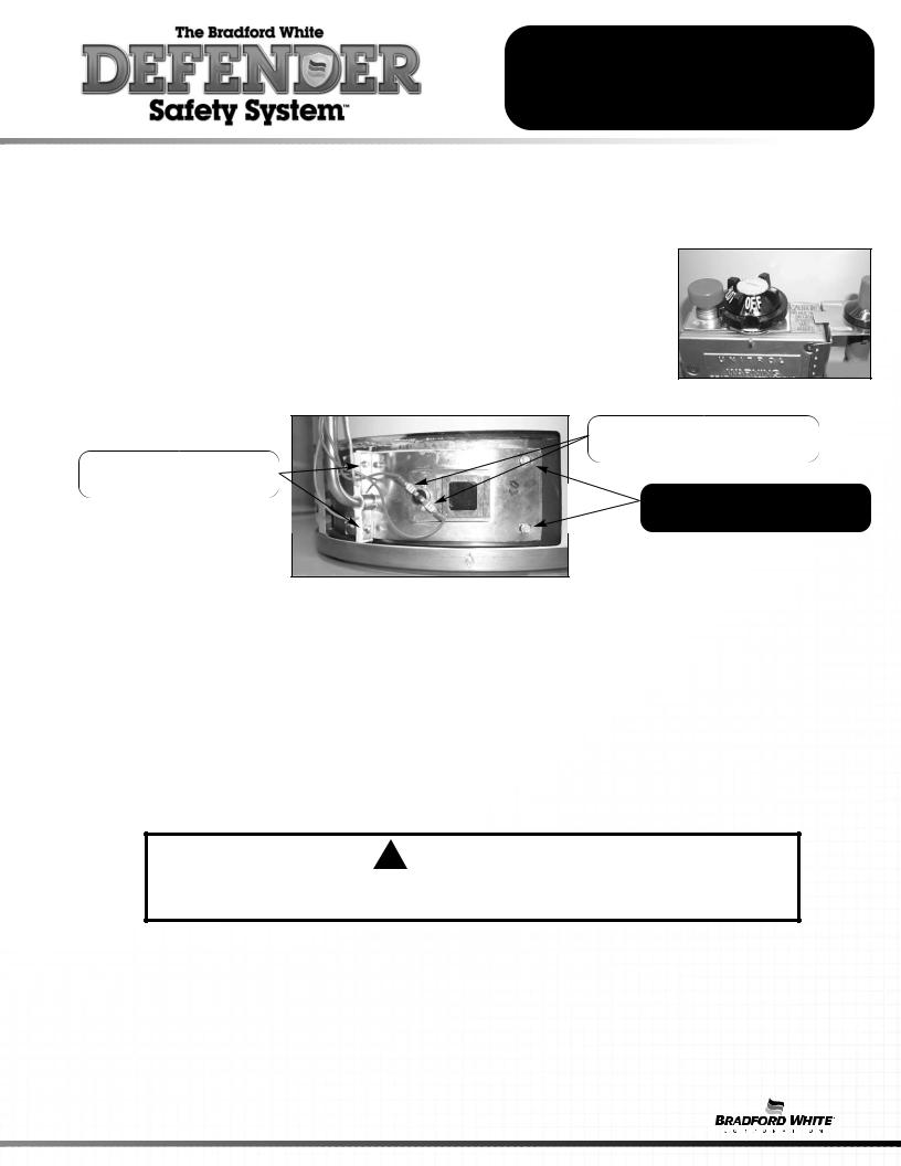
Step 1. Rotate knob of the combination thermostat/gas valve to the “OFF” position. Step 2. Remove outer jacket burner access door
Step 3. Inner Door Removal.
a)Disconnect resettable thermal switch wire leads (leading from combination thermostat/gas valve).
b)Remove (2) 1/4" hex drive screws from right side inner door.
c)Remove (2) 1/4" drive screws from flange section of inner door.
d)Remove (2) 1/4" drive screws from left side inner door.
e)Remove inner door and inspect per step 4.
Resettable Thermal Switch
Wire Connection
1/4" Hex Drive Screws at
Flange Area of Inner Door
1/4" Hex Drive Screws
Right and Left Side Inner Door
Step 4. |
Fully inspect inner door gaskets for the following: |
|
|
>Tears |
>Other imperfections that will inhibit proper seal |
|
>Missing Material |
>Gasket adhesion to inner door |
|
>Cracks |
>Material left on combustion chamber (around opening) |
|
>Dirt or debris |
|
If the gasket is not effected by any of the above, gasket replacement is not required.
If replacement is required, proceed to Inner Door Gasket Replacement Procedure.
Inner Door Gasket Replacement Procedure
! WARNING
If the information in these instructions is not followed exactly, a fire or explosion may result causing property damage, personal injury or death.
Step 5. After inspection of inner door as noted in step 4, completely remove gasket and adhesive residue from right and left side inner doors as needed.
Step 6. Use RTV sealant (recommended bead size 1/8") to secure the inner door gasket to the inner door sections (right & left). Refer to illustration on next page for proper application. Note the overlap configuration in the flange area of the inner door. Set the flange section first, this will help to achieve the proper over lap position.
5

SERVICE PROCEDURE RG-I
Inner Door/Gasket Removal, Inspection
Replacement and Reinstallation
Installation of Inner Door with Gasket
Step 7. |
Clean any residual gasket residue or other debris |
||||
|
|
from combustion chamber surface before |
|||
|
|
installing the inner door/gasket assembly. |
|||
Step 8. |
into position first. |
||||
|
|
channel of the inner |
|||
|
|
|
|
the 1/4” hex |
|
|
|
|
|
left side inner |
|
|
|
SCREWS. |
|||
Step 9. |
tube and Piezo wire |
||||
|
|
|
|
gasket. |
|
|
|
|
|
RADIUSED |
|
|
|
. |
|
|
|
|
|
|
|
|
|
|
|
|
|
|
|
! WARNING
Stripped fastener connections may allow for seal breach of inner door. A seal breach may result in a fire or explosion causing property damage, personal injury or death. Do not over tighten screws in steps 8, 10 and 11.
If a fastener connection is stripped, contact the manufacturer listed on the water heater rating plate.
Radiused Channel for Feedline |
Position thermocouple, |
|
pilot tube and Piezo wire |
||
|
6
SERVICE PROCEDURE RG-I
Inner Door/Gasket Removal, Inspection
Replacement and Reinstallation
Step 10. Firmly place right side inner door flange against the left side inner door flange and secure with two 1/4” drive screws from step 3c. DO NOT OVER TIGHTEN SCREWS.
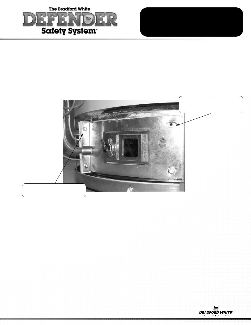
Step 11. Align right side inner door to combustion chamber and verify the fastener holes of the combustion chamber are aligned with the right side inner door slotted opening. Verify seal integrity around combustion chamber opening. Secure right side inner door using 1/4” hex drive screws from step 3b.
DO NOT OVER TIGHTEN SCREWS. Verify both left and right sides of the inner door are properly positioned and sealed against the combustion chamber.
Verify threaded hole alignment with slotted openings in inner door
Secure flange with 1/4" drive screws
Step 12. Reconnect lead wires from combination thermostat/gas valve to in step 3). Note, wire terminations are interchangeable with either connections.
Step 13. Replace outer jacket burner access door.
Step 14. To resume operation follow the instructions located on the lighting instructions located in the installation and operation manual.
7
SERVICE PROCEDURE RG-II
Thermocouple Testing and Replacement
Closed Circuit Thermocouple Testing
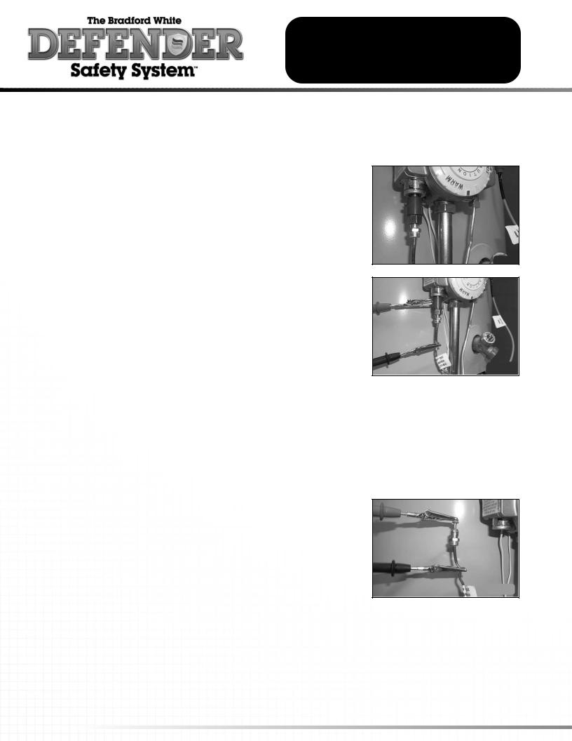
Step 1. Disconnect thermocouple from combination thermostat/gas valve.
Step 2. Connect a thermocouple adapter (BWC P/N 239-44642-00, Robertshaw P/N 75036) at the thermocouple location in the combination thermostat/gas valve.
Step 3. Reconnect thermocouple to adapter. make certain all connections are tight (finger tight plus 1/4 turn)
Step 4. Using a multimeter capable of measuring millivolts, connect one alligator clip to the set screw of the adapter, and the other alligator clip to copper portion of the thermocouple.
Step 5. Following the lighting instruction label on the heater, proceed to light the pilot and allow to operate for three minutes. If the pilot will not stay lit, hold the red reset button (located on the combination thermostat/gas valve) down during this test.
Step 6. If meter reads 13 millivolts or higher, the thermocouple is OK. If reading is below13 millivolts replace the thermocouple.
Open Circuit Thermocouple Testing
Step 1. Disconnect thermocouple from combination thermostat/gas valve.
Step 2. Using a multimeter capable of measuring millivolts, connect one alligator clip to the end ball or contact portion of the thermocouple, and the other alligator clip to copper portion of the thermocouple.
Step 3. Following the lighting instruction label on the heater, proceed to light the pilot and allow to operate for three minutes. It will be necessary to hold the red reset button continuously
throughout this test. If meter reads 20 millivolts or higher, the thermocouple is OK. If reading is below20 millivolts, replace the thermocouple.
8
SERVICE PROCEDURE RG-II
Thermocouple Testing and Replacement
Thermocouple Replacement
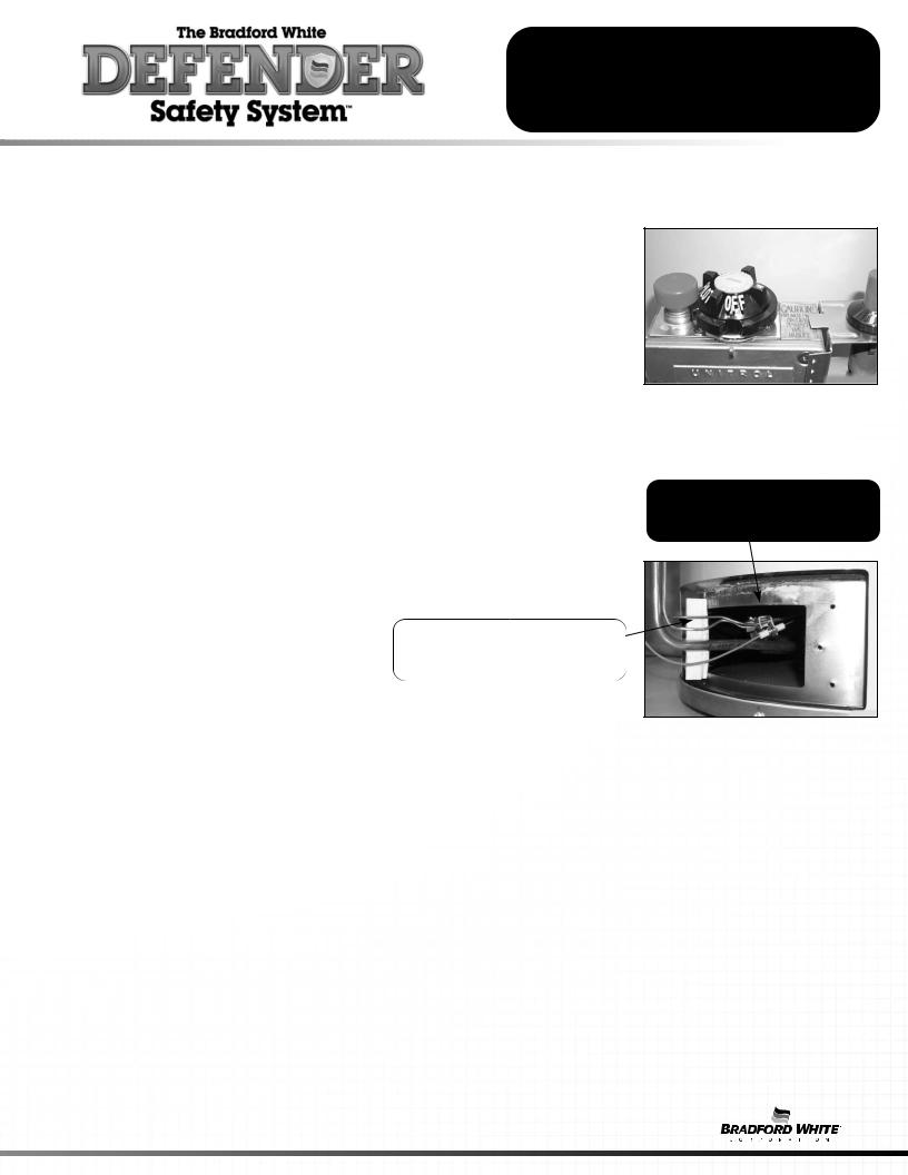
Step 1. Turn off gas supply to water heater. Rotate knob of combination thermostat/gas valve to “OFF” position.
Step 2. Remove outer jacket door.
Step 3. Remove right side of inner door per SERVICE PROCEDURE RG-I, steps 3a through 3c.
Step 4. Disconnect thermocouple from combination thermostat/gas valve (3/8" wrench). Locate other end of thermocouple inside of combustion chamber and remove from pilot bracket. Pull firmly pulling away from the pilot assembly.
Step 5. Install new thermocouple into pilot bracket making certain thermocouple is fully engaged into the pilot bracket. Position thermocouple against left side inner door flange at its original position. Connect other end of thermocouple to combination thermostat/gas valve (finger tight + 1/4 turn).
Position thermocouple, in its original position
Make certain thermocouple is fully engaged into bracket
Step 6. Inspect inner door gasket per SERVICE PROCEDURE RG-I, Step 4.
Step 7. Install right side inner door per SERVICE PROCEDURE RG-I, Step 10 through Step 13.
Step 8. To resume operation follow the instructions located on the lighting instruction label or the lighting instructions located in the installation and operation manual.
9
 Loading...