

Boss Audio MR2080W User Manual

CONTENTS
MR2080W User’s Manual - page 1
U S E R ’ S M A N U A L
MR2080W Marine MP3/CD Receiver Packing List
Before installing your new CD Receiver, please unpack the contents and check
that your package contains the following items:
2 Head unit installation
6 Remote control installation
Flush mount
6 Remote control installation
Surface mount
10 General and tuner controls
14 Remote control
15 CD Playback
15 MP3 playback
16 RDS radio functions
17 PTY station categories
18 Wiring diagram
19 Troubleshooting
20 Specifications
Congratulations on your
purchase of a Marine
MP3/CD Receiver.
It has been designed, engineered
and manufactured to bring you
the highest level of performance
and quality, and will afford you
years of listening pleasure.
Thank you for making
Marine your choice for
marine audio entertainment!
Main unit
Mounting hardware for main unit:
Mounting brackets (2) with adhesive tape
Mounting sheet (paper with hole markings)
Mounting screws, M4 x 30mm (4)
Rubber sealing gasket
Rear mounting bracket
Plain washer
Spring washer
Screw, M5 x 25mm
Hex nut
Wiring harness
Wired remote control
Remote control cable
Mounting hardware for remote control:
Mounting arms (2)
Mounting tube (1)
Machine screws (2)
User’s manual
Warranty card
MR2080W
Fully Marinized
MP3-Compatible CD Receiver
page
RDS Model with
Switchable USA/European
Frequencies
MR2080W User’s Manual - page 2
Head unit installation
Before installing your new
CD Receiver, please become familiar
with all the information contained in
this manual.
Choose a mounting location where the
unit will not distract or otherwise
interfere with the pilot’s ability to control
the boat.
Use only the installation parts and
hardware provided with the unit to
ensure proper installation. Using other
parts can cause malfunction and
possible damage to your CD
receiver.
Do not install this unit at an angle in
excess of 30º from horizontal, as it
may affect performance.
Although this unit has been designed
for outdoor use, you can extend its life
if you install it in a location which is
not subject to extreme temperatures,
from such sources as heaters or
exhaust lines. Also, if you see dirt, dust
or debris on a disc or in the CD slot,
remove it with a clean cloth to avoid
pushing it into the player mechanism.
To remove dirt from the faceplate, use
a clean cloth lightly moistened with
filtered water. If the unit is splashed
with water, wipe it off with such a clean
damp cloth before the water has dried
to avoid an accumulation of salts on
the face of the unit.
If properly installed, this unit will meet
the IPX5 Waterproof standard. Please
note that this does NOT mean the unit
is submersible, but will resist being
sprayed and splashed as might occur
in a normal boat cabin.
To ensure that the installation
meets the IPX5 Waterproof
Standard, please follow these steps
carefully.
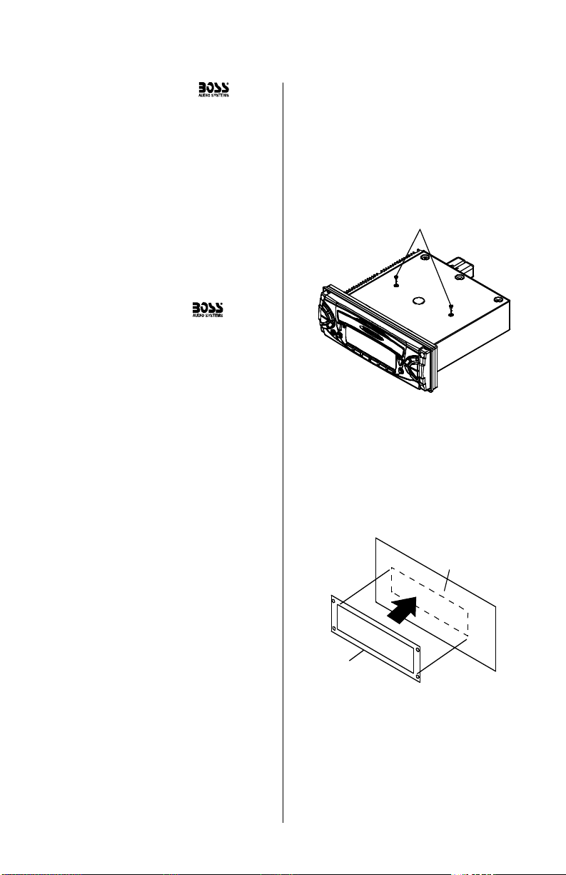
1. Remove the transport screws from
the top of the enclosure before
beginning the installation.
Remove transport screws
2. Examine the mounting sheet
included with the unit. Decide on the
location you wish to put the unit, and
stick this sheet to the dash there.
Dashboard
Mounting sheet
Stick mounting sheet to dashboard
in mounting location
MR2080W User’s Manual - page 3
Head unit installation, continued
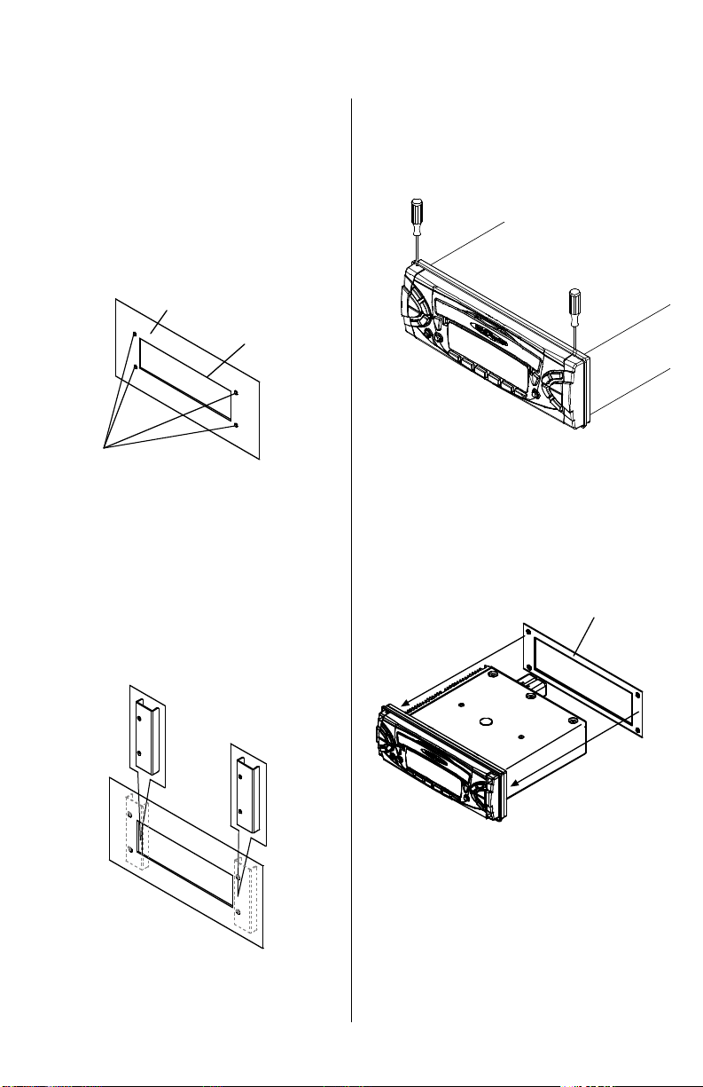
3. Using a sharp knife, saw or other
appropriate tools as may be required,
cut out the rectangular shape specified
on the mounting sheet. Then drill the
four 3/16” (5mm) mounting holes in
the EXACT locations shown on the
mounting sheet.
4. Using the double-faced adhesive
paper provided, stick the mounting
brackets in place behind the opening.
Before you press them firmly in
place, be certain that the holes in
the bracket are visible through the
holes you made in the dashboard!
5. Carefully pop off the plastic
mounting screw covers from the
faceplate to reveal the four mounting
holes. Use a small, flat-bladed
screwdriver for this purpose.
5. Slide the rubber sealing gasket from
the back of the unit until it is snug against
the rear surface of the faceplate.
Dashboard
Cut hole as shown on
mounting sheet.
Drill four 3/16” (5mm) holes
for mounting screws.
Use double-faced tape
to attach brackets to inside
face of dashboard.
Mounting
brackets
Rubber sealing gasket
Put the rubber gasket in
place on the rear surface
of the faceplate.
MR2080W User’s Manual - page 4
Head unit installation, continued
PLEASE NOTE: If your installation is such
that once you install the head unit into the
dashboard you will NOT have access to
the audio and power connectors or cables,
make all your connections at this time.
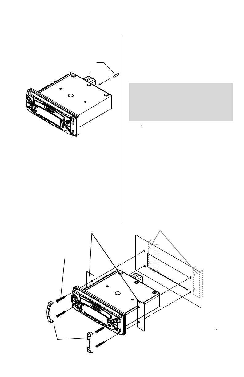
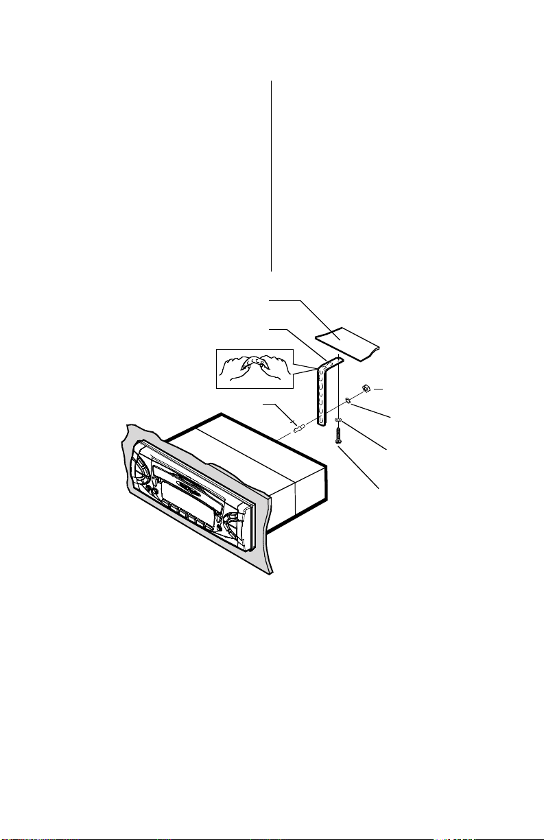
6. Insert and tighten the support screw
into the back of the head unit where
shown.
7. Mount the unit in place using the
four M4 x 30mm screws provided.
These screws go through the front
panel, then the mounting places, then
dashboard, and finally engage in the
mounting brackets.
Tighten them securely and then snap
the mounting screw covers back in
place.
Dashboard
Mounting brackets (2)
(installed in Step 4)
Mounting plates (2)
M5 x 30mm
screws (4)
Mounting
screw covers
support screw
MR2080W User’s Manual - page 5
Head unit installation, continued
8. Insert the head unit into the
dashboard. Inspect the dashboard
material to determine its approximate
thickness.
Bend the backstrap to conform to the
mounting case and the dashboard
surface to which you plan to secure
the backstrap. Slide one of the utility
holes on the backstrap onto the
support screw and fasten it with the
spring washer and nut provided.
support strap
dashboard attachment
surface
support screw
M5 x 25mm
support screw
plain
washer
spring
washer
5mm nut
MR2080W User’s Manual - page 6
Remote control installation
FLUSH MOUNT
The Marine Remote Commander
has been designed with particular
attention to ease and flexibility in
installation.
It can be mounted in both flush-mount
and surface mount situations. Both
use our exclusive “push and turn”
system. In both types of mountings,
you will first attach the mounting cup
in place.
Once the cup is secure, you simply
feed the wires thru the hole in the back
of the cup (flush mount) or the lower
edge of the cup (surface mount) and
then insert and turn the remote until it
is engaged.
Place O-ring in groove on rear surface of flange of cup.
Follow these steps for a successful
installation:
1. Select the proper location which
accomodates the 3.45” overall
diameter, and mark its centerpoint.
2. Drill a hole with diameter of 3.2”-
3.3” (82-84mm). It is very important
that the hole does not exceed 3.3”.
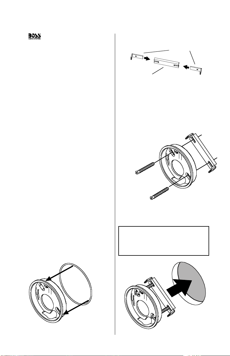
3. Place the O-ring provided in the
groove on the rear surface of the flange
of the mounting cup.
4. Insert mounting arms fully into
mounting tube.
Mounting arms
Mounting tube
5. Insert mounting screws provided
through the slots in the cup and into
the threaded holes in the mounting
arms. Do not tighten more than a few
turns.
6. Insert this assembly fully into the
hole you have cut so that the flange
rests on the the mounting surface.
Be sure the cup is oriented with
arrow next to the word TOP is
pointing UP or your remote will be
turned when it is installed!
Insert the cup assembly fully into
the hole you have cut.
Insert the mounting screws through
the cup into the threaded holes
in the mounting arms
 Loading...