

Boss Audio MP3-4600R User Manual

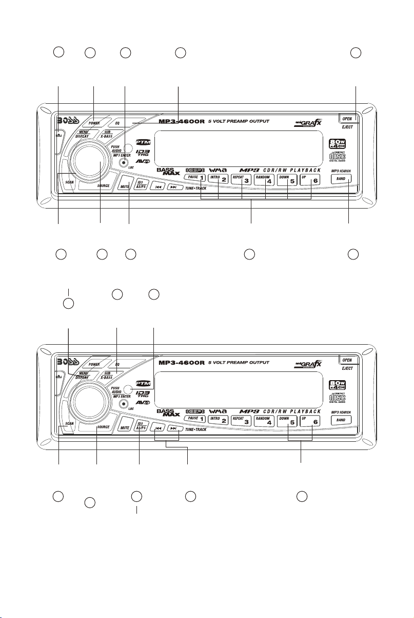
1. BUTTONS LOCATION AND FUNCTIONING
1
PANEL
RELEASE
BUTTON
ENCODER
VOLUME
BUTTON
10
MENU
BUTTON
DISPLAY
BUTTON
6
POWER
BUTTON
AUDIO
BUTTON
SUB-WOOFER
LOCAL / DX
BUTTON
5
IX-BASS/
BUTTON
3
MUTE
BUTTON
8
2
15
REMOTE
CONTROL
RECEIVER
1712
PRESET
EQUALIZER
BUTTON
PRESET MEMORY BUTTONS (M1~M6)
4
PANEL
OPEN/EJECT
BUTTON
BAND/LOUDNESS
BUTTON
7
13
MP3 SEARCH
BUTTON
SCAN
BUTTON
9
SOURCE
BUTTON /
SUB-WOOFER
LEVEL CONTOL
16
AUTOMATICALLY
STORE / PRESET
SCAN BUTTON
11
ID3 TAG
INFORMATION
TUNING UP / DOWN
TRACK UP / DOWN
BUTTONS
14
E - 1
FOLDER DOWN
/UP BUTTONS
18
2. HANDLING COMPACT DISCS
MOISTURE CONDENSATION
On a rainy day or in a very damp area, moisture may condense on the lenses inside the unit. Should this
occur, the unit will not operate properly. In such a case, remove the disc and wait for about an hour until
the moisture has evaporated.
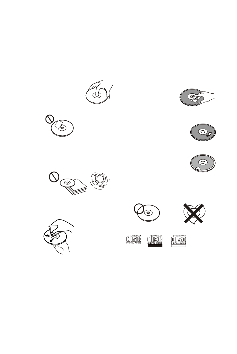
NOTES ON CDs
1.
A dirty or defective disc may cause sound
dropouts while playing. To enjoy optimum
sound, handle the disc as follows.
Handle the disc by its edge. To keep the disc
clean, do not touch the surface (P.1).
P. 1
Do not stick paper or tape on the disc (P.2).
2.
P. 2
Do not expose the discs to direct sunlight or
3.
heat sources such as hot air-ducts, or leave
them in a car parked in direct sunlight where
there can be a considerable rise in
temperature inside the car (P.3).
P. 3
4.
Before playing, clean the discs with an
optional cleaning cloth. Wipe each disc from
the centre out (P.4).
NOTES ON DISCS
If you use the discs explained below, the sticky
residue can cause the CD to stop spinning and
may cause malfunction or ruin your discs.
Do not use second-hand or rental CDs that have a
sticky residue on the surface (for example, from
peeled-off stickers or from ink, or glue leaking
from under the stickers).
There are paste residue.
Ink is sticky (P.5).
P. 5
Do not use rental CDs with old labels that are
beginning to peel off.
Stickers that are beginning
to peel away, leaving a
sticky residue (P.6).
P. 6
Do not use your CDs with labels or stickers
attached.
Labels are attached (P.7).
Do Not Use Special Shape CDs
P. 7
Be sure to use round shape CDs only for this
unit and do not use any special shape CDs.
Use of special shape CDs may cause the unit
to malfunction.(P.8).
P. 8
Be sure to use CDs with disc mark
*******
*******
*******
*******
*******
****
**************
*******
*******
*******
*******
*******
*******
*******
P. 4
Do not use solvents such as benzine,
5.
thinner,commercially available cleaners, or
antistatic spray intended for analog discs.
RECORDABLE
REWRITABLE
Only for this unit.
CD-Rs and CD-RWs which have not undergone
finalization processing cannot be played. (For
more information on finalization processing,
refer to the manual for your CD-R/CD-RW
writing software or CD-R/CD-RW recorder.)
Additionally, depending on the recording status,
it may prove impossible to play certain CDs
record on CD-R or CD-RW.
E - 2
3. INSTALLATION
Before finally installing the unit, connect the wiring temporarily and make sure it is all connected up
properly and the unit and system work properly.
Use only the parts included with the unit to ensure proper installation. The use of unauthorized parts
can cause malfunctions.
Consult with your nearest dealer if installation requires the drilling of holes or other modifications of the
vehicle.
Install the unit where it does not get in the driver's way and cannot injure the passenger if there is a
sudden stop, like an emergency stop.
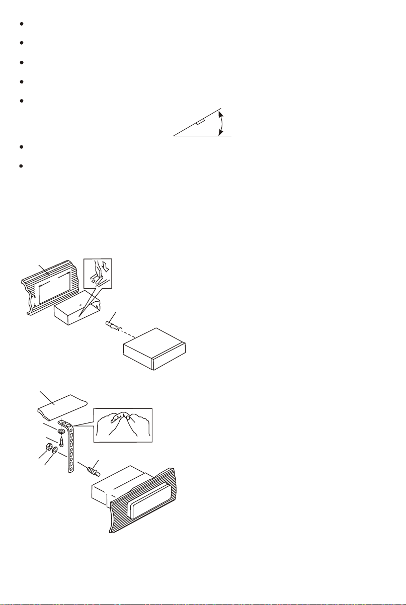
If installation angle exceeds 30° from horizontal, the unit might not give its optimum performance.
30°
Avoid installing the unit where it would be subject to high temperature, such as from direct sunlight, or
from hot air, from heater, or where it would be subject to dust dirt or excessive vibration.
Be sure to remove the front panel before installing the unit.
DIN FRONT/REAR-MOUNT
This unit can be property installed either from “Front” (conventional DIN Front-mount) or “Rear”(DIN
Rear-mount installation, utilizing threaded screw holes at the sides of the unit chassis). For details,
refer to the following illustrated installation methods A and B.
DIN FRONT-MOUNT (Method A)
Installation the unit
1
2
182
53
3
1. Dashboard
2. Holder
After inserting the half sleeve into the
dashboard, select the appropriate tab according
to the thickness of the dashboard material and
bend them inwards to secure the holder in
place.
3. Screw
1
7
4
2
3
6
5
1. Dashboard
2. Nut (5mm)
3. Spring washer
4. Screw (5x25mm)
5. Screw
6. Support Strap
Be sure to use the support strap to secure the
back of the unit in place. The strap can be bent
by hand to the desired angle.
7. Plain washer
E - 3
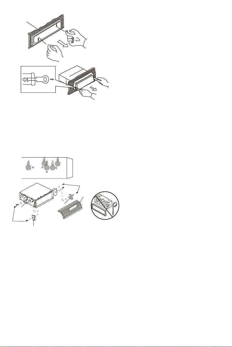
Removing the unit
a
b
c
Trim Plate Installation:
Push the trim plate against the chassis until it is fitted.
You must do this before you install the front panel, otherwise it can't be attached.
DIN REAR-MOUNT (METHOD B)
Installation using the screw holes on the sides of the unit.
Fastening the unit to the factory radio mounting bracket.
2
4
5
3
2
5
a. Frame
b. Insert fingers into the groove in the front
of frame and pull out to remove the
frame. (When re-attaching the frame,
point the side with a groove down wards
and attach it.)
c. Insert the levers supplied with the unit
into the grooves at both sides of the unit
as shown in figure until they click. Pulling
the levers makes it possible to remove
the unit from the dashboard.
1. Select a position where the screw
holes of the bracket and the screw
holes of the main unit become
aligned (are fitted) and tighten the
screws at 2 places on each side.
2. Screw
3. Factory radio mounting bracket.
4. Dashboard or Console
5. Hook (Remove this part)
Note: the mounting box, outer trim ring,
and half-sleeve are not used for method
B installation.
E - 4
4. DETACHABLE CONTROL PANEL (D.C.P.)
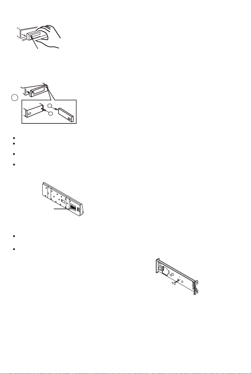
Removing The Detachable Control Panel (D.C.P.).
1. Turn the power off
2. Press the D.C.P. release button
PANEL RELEASE
BUTTON
Attaching the DCP
3. Remove the D.C.P.
2
A
B
1. Attach the panel at the right side first, with
point B on the main unit touching point A on the
D.C.P. (As shown on the digram).
2. Then press the left side of D.C.P. onto the main
unit until a “click” sound is heard.
CAUTION
DO NOT insert the D.C.P from the left side. Doing so may damage it.
The D.C.P can easily be damaged by shocks. After removing it, place it in a protective case and be careful not to drop
it or subject it to strong shocks.
When the release button is pressed and the D.C.P is unlocked, the car's vibrations may cause it to fall. To prevent
damage to the D.C.P, always store it in a protective case after detaching it.
The rear connector that connects the main unit and the D.C.P is an extremely important part. Be careful not to
damage it by pressing on it with fingernails, pens, screwdrivers, etc.
Note:
If the D.C.P is dirty, wipe off the dirt with soft,
dry cloth only. And use a cotton swab soaked
Socket
in isopropyl alcohol to clean the socket on the
back of the D.C.P.
RESETTING THE UNIT:
After releasing the front panel, use a pencil or any non-metalic object to press & hold the
reset button for five seconds to reset the unit.
Long press the eject button for more than 6 seconds to reset / resume the CD Deck
mechanism.
R
E
S
E
T
E - 5

5. WIRING DIAGRAM (20 PIN HARNESS PLUG)
YELLOW
RED
R-CH
L-CH
WHITE
AUX IN
LEFT FRONT
WHITE-BLACK LF-
WHITE LF+
LEFT REAR
FUSE
20-PIN
AUDIO/POWER
HARNESS
(See Figure 1)
-
GREEN-BLACK LR
GREEN LR+
GREY
REAR LINE OUT
BLACK
FRONT LINE OUT
RIGHT FRONT
GREY-BLACK RF-
GREY RF+
RIGHT REAR
VIOLET-BLACK RR-
VIOLET RR+
BLUE
SUB WOOFER
WHITE
RED
WHITE
RED
BLUE
BLACK
YELLOW
RED
RCA-TO-RCA CABLES
WHITE
L-CH
R-CH
L-CH
R-CH
(NOT SUPPLIED)
RCA-TO-RCA CABLES
(not supplied)
Power Antenna
Connect to power antenna or amplifier,If
not used,Tape bare end of wire.
Ground Connect to ground terminal or
Pclean unpainted metal part of
Memory/Battery
Connect to battery or 12 volt power sourse that is always live.
The radio will not work if this wire is not connected
Accessory/Ignition Connect to existing radio wire or radio fuse.
20-PIN AUDIO/POWER HARNESS
141311 12 15 16
Figure 1
ANTENNA
JACK
SUB-WOOFER
AMP
chassis
ANTENNA
EXTENDER
CABLE
653 41 2
7 98 10
201817 19
Pin View
WIRE COLOR
PIN
1 GREY/BLACK
2 GREY
3 VIOLET
4 VIOLET/BLACK
5
6 GREEN
7 GREEN/BLACK
8 RED
9 BLACK
10 RED
FUNCTION/LABEL
RIGHT FRONT SPEAKER (-)
RIGHT FRONT SPEAKER (+)
RIGHT REAR SPEAKER (+)
RIGHT REAR SPEAKER (-)
LEFT REAR SPEAKER (+)
LEFT REAR SPEAKER (-)
IGNITION(ACC)
REAR PRE-AMP LINE OUT COMMON
RIGHT REAR PRE-AMP LINE OUT
E - 6
PIN
11
12
13
14
15
16
17
18
19
20
WIRE COLOR
WHITE
WHITE/BLACK
BLUE
YELLOW
BLACK
WHITE
RED
BLACK
WHITE
FUNCTION/LABEL
LEFT FRONT SPEAKER (+)
LEFT FRONT SPEAKER (-)
POWER ANTENNA
BATTERY(+)
CHASSIS GROUND
LEFT FRONT PRE-AMP LINE OUT
RIGHT FRONT PRE-AMP LINE OUT
FRONT PRE-AMP LINE OUT COMMON
LEFT REAR PRE-AMP LINE OUT
 Loading...