

Boss Audio 765DBI User Manual

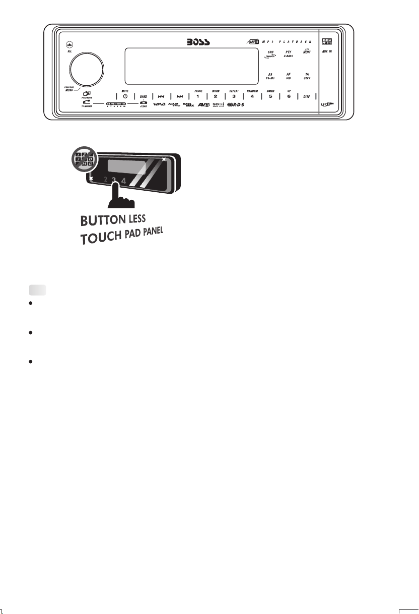
This radio is equipped with the most advanced "TOUCH SENSE PANEL", so that it is
easy and convenient to use while driving.
Tips; Here are some tips to show you how easy it is to use this touch sense panel:
Tips
Using a very light touch on the radio panel will activate that feature. You will not need to
"PRESS" hard on the panel to make this radio change features.
The power button along with some of the buttons that have dual functions, will need to be
"TOUCHED" from 2 to 3 seconds to make the change.
The best area to "TOUCH" on the panel to make it activate is the illuminated or lighted area. For
example, just touch for 2 to 3 seconds the illuminated power symbol and the unit will turn on or
off.
1. INSTALLATION
Before finally installing the unit, connect the wiring temporarily and make sure it is all
connected up properly and the unit and system work properly.
Use only the parts included with the unit to ensure proper installation. The use of
unauthorized parts can cause malfunctions.
Consult with your nearest dealer if installation requires the drilling of holes or other
modifications of the vehicle.
Install the unit where it does not get in the driver's way and cannot injure the passenger if
there is a sudden stop, like an emergency stop.
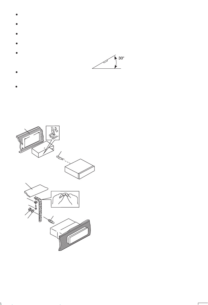
If installation angle exceeds 30°from horizontal, the unit might not give its optimum
performance.
Avoid installing the unit where it would be subject to high temperature, such as from direct
sunlight, or from hot air, from heater, or where it would be subject to dust dirt or excessive
vibration.
Be sure to remove the front panel before installing the unit.
DIN FRONT/REAR-MOUNT
This unit can be property installed either from “Front” (conventional DIN Front-mount) or “Rear”(DIN
Rear-mount installation, utilizing threaded screw holes at the sides of the unit chassis). For details,
refer to the following illustrated installation methods A and B.
DIN FRONT-MOUNT (Method A)
Installation the unit
1
182
53
2
3
1. Dashboard
2. Holder
After inserting the half sleeve into the
dashboard, select the appropriate tab
according to the thickness of the
dashboard material and bend them
inwards to secure the holder in place.
3. Screw
1
7
4
2
3
6
1. Dashboard
2. Nut (5mm)
3. Spring washer
4. Screw (4x12mm)
5
5. Screw
6. Support Strap
Be sure to use the support strap to secure
the back of the unit in place. The strap can
be bent by hand to the desired angle.
7. Plain washer
2
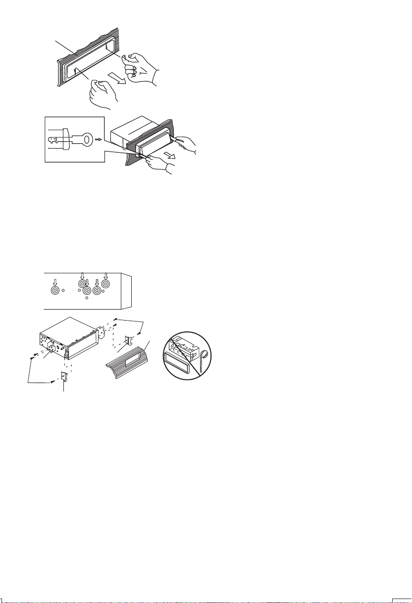
Removing the unit
a
a. Frame
b. Insert fingers into the groove in the
front of frame and pull out to remove
the frame. (When re-attaching the
b
c
Trim Plate Installation:
Push the trim plate against the chassis until it is fitted.
You must do this before you install the front panel, otherwise it can't be attached.
DIN REAR-MOUNT (METHOD B)
Installation using the screw holes on the sides of the unit.
Fastening the unit to the factory radio mounting bracket.
2
4
5
3
2
5
frame, point the side with a groove
down wards and attach it.)
c. Insert the levers supplied with the
unit into the grooves at both sides of
the unit as shown in figure until they
click. Pulling the levers makes it
possible to remove the unit from the
dashboard.
1. Select a position where the screw
holes of the bracket and the screw
holes of the main unit become
aligned (are fitted) and tighten the
screws at 2 places on each side.
2. Screw
3. Factory radio mounting bracket.
4. Dashboard or Console
5. Hook (Remove this part)
Note: the mounting box, outer trim ring,
and half-sleeve are not used for method
B installation.
3
2. DETACHABLE CONTROL PANEL (D.C.P.)
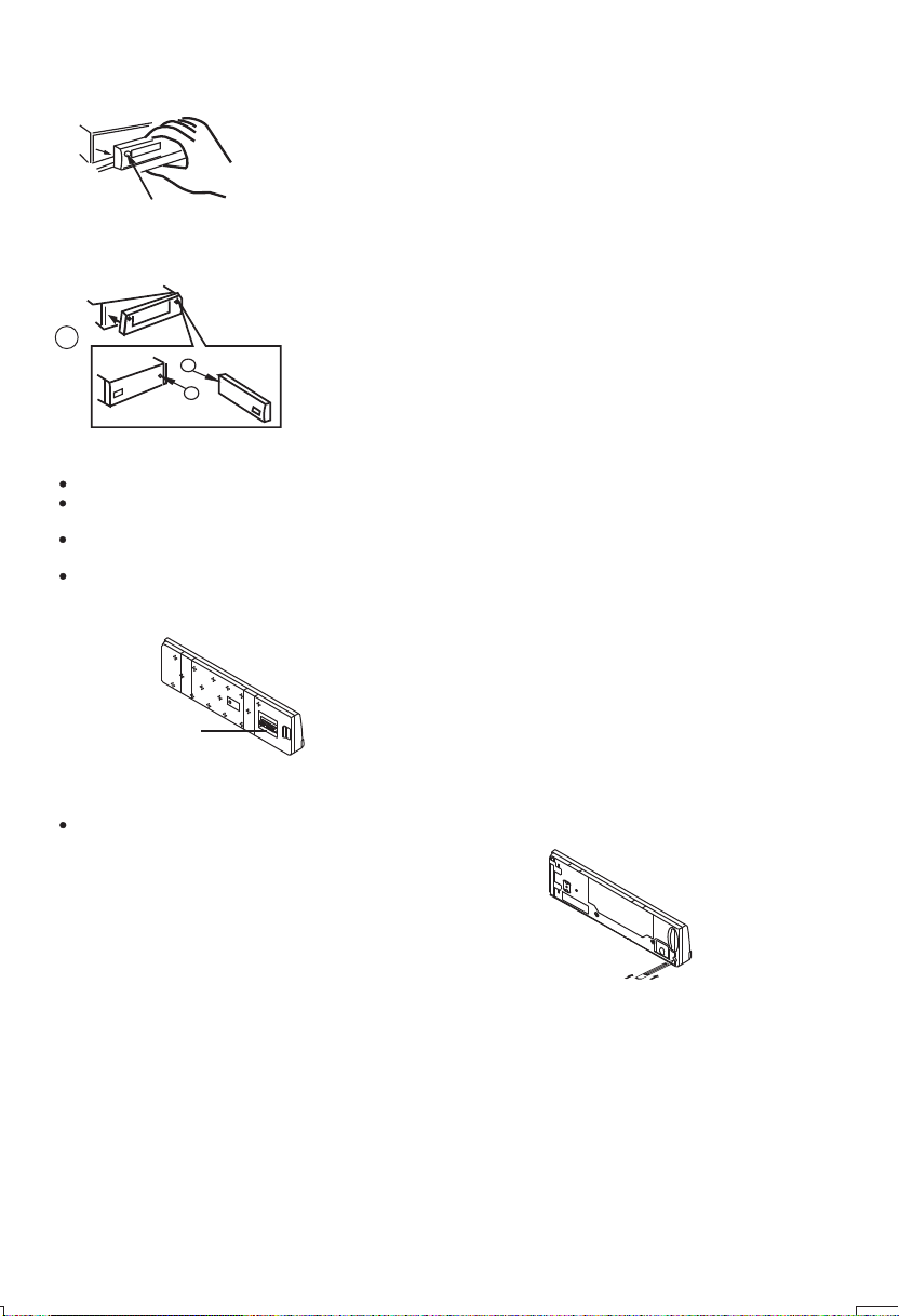
Removing The Detachable Control Panel (D.C.P.).
1. Turn the power off
2. Press the D.C.P. release button
PANEL RELEASE
BUTTON
Attaching the DCP
3. Remove the D.C.P.
2
A
B
1. Attach the panel at the right side first, with
point B on the main unit touching point A on the
D.C.P. (As shown on the diagram).
2. Then press the left side of D.C.P. onto the main
unit until a “click” sound is heard.
CAUTION
DO NOT insert the D.C.P from the left side. Doing so may damage it.
The D.C.P can easily be damaged by shocks. After removing it, place it in a protective case and be careful not
to drop it or subject it to strong shocks.
When the release button is pressed and the D.C.P is unlocked, the car's vibrations may cause it to fall. To
prevent damage to the D.C.P, always store it in a protective case after detaching it.
The rear connector that connects the main unit and the D.C.P is an extremely important part. Be careful not to
damage it by pressing on it with fingernails, pens, screwdrivers, etc.
Note:
If the D.C.P is dirty, wipe off the dirt with soft,
dry cloth only. And use a cotton swab soaked
in isopropyl alcohol to clean the socket on the
Socket
back of the D.C.P.
RESETTING THE UNIT:
After releasing the front panel, use a pencil or any non-metalic object to press & hold the
reset button for five seconds to reset the unit.
Reset
4
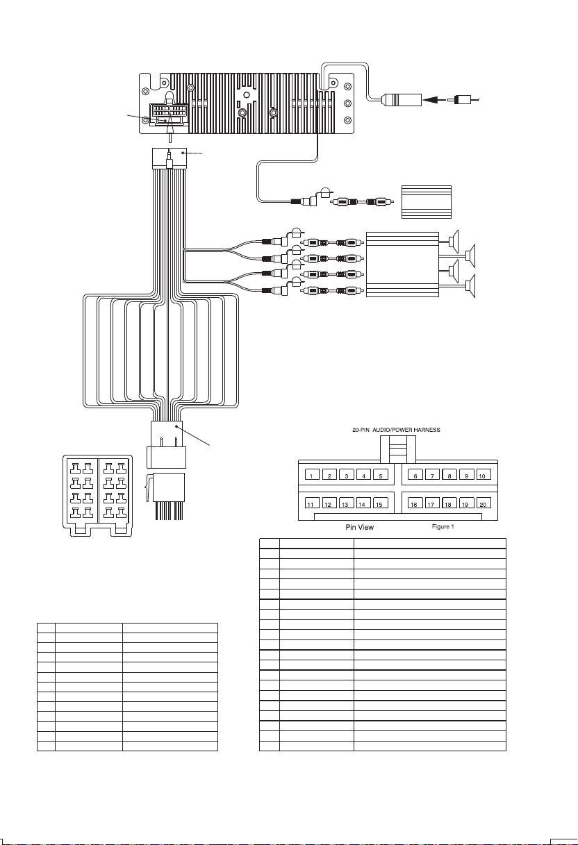
3. WIRING DIAGRAM (20 PIN + ISO PLUG)
FUSE
20-PIN
AUDIO/POWER
HARNESS
(See Figure 1)
GREY
REAR LINE OUT
BLACK
FRONT LINE OUT
BLUE
SUB WOOFER
WHITE
L-CH
RED
R-CH
WHITE
L-CH
RED
R-CH
WHITE
RCA-TO-RCA CABLES
(not supplied)
RCA-TO-RCA CABLES
(not supplied)
ANTENNA
JACK
Subwoofer Amp
AMP
ANTENNA
EXTENDER
CABLE
PIN(B8) GREEN/BLACK
PIN(B7) GREEN
CONNECTOR B
8
5
6
3
4
1
2
Figure 2
ISO CONNECTOR 4PIN+8PIN
FEMALE WITH MALE TERMINAL
ISO CONNECTOR WIRING CHART
WIRE COLOR
PIN
YELLOW
A4
BLUE
A5
RED
A7
BLACK
A8
VIOLET
B1
VIOLET/BLACK
B2
GREY
B3
GREY/BLACK
B4
WHITE
B5
WHITE/BLACK
B6
GREEN
B7
GREEN/BLACK
B8
PIN(B2) VIOLET/BLACK
PIN(B4) GREY/BLACK
PIN(B3) GREY
PIN(B5) WHITE
PIN(B6) WHITE/BLACK
CONNECTOR A
7
87
5 6
3 4
1 2
FUNCTION/LABEL
CONSTANT 12 VOLTS
POWER ANTENNA/REMOTE TURN ON
IGNITION(ACC)
GROUND
RIGHT REAR SPEAKER (+)
RIGHT REAR SPEAKER (-)
RIGHT FRONT SPEAKER (+)
RIGHT FRONT SPEAKER (-)
LEFT FRONT SPEAKER (+)
LEFT FRONT SPEAKER (-)
LEFT REAR SPEAKER (+)
LEFT REAR SPEAKER (-)
PIN(B1) VIOLET
PIN(A8) BLACK
CONNECTOR
(See Figure 2)
PIN(A7) RED
PIN(A5) BLUE
ISO
PIN(A4) YELLOW
PIN
1
2
3
4
5
6
7
8
9
10
11
12
13
14
15
16
17
18
19
20
WIRE COLOR
GREY/BLACK
GREY
VIOLET
VIOLET/BLACK
GREEN
GREEN/BLACK
RED
BLACK
RED
WHITE
WHITE/BLACK
BLUE
YELLOW
BLACK
WHITE
RED
BLACK
WHITE
FUNCTION/LABEL
RIGHT FRONT SPEAKER (-)
RIGHT FRONT SPEAKER (+)
RIGHT REAR SPEAKER (+)
RIGHT REAR SPEAKER (-)
LEFT REAR SPEAKER (+)
LEFT REAR SPEAKER (-)
IGNITION(ACC)
REAR PRE-AMP LINE OUT COMMON
RIGHT REAR PRE-AMP LINE OUT
LEFT FRONT SPEAKER (+)
LEFT FRONT SPEAKER (-)
POWER ANTENNA/REMOTE TURN ON
CONSTANT 12 VOLTS
CHASSIS GROUND
LEFT FRONT PRE-AMP LINE OUT
RIGHT FRONT PRE-AMP LINE OUT
FRONT PRE-AMP LINE OUT COMMON
LEFT REAR PRE-AMP LINE OUT
5
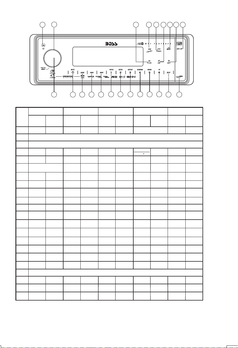
4. CONTROL PANEL FUNCTION
3
OPERATIONS:
SYSTEM TUNER MP3/W MA
KEY
Sho rt
Pre ss
Mut e Pow er
1
2
3
4
Mod e
5
Enc oder Vol ume
6
7
8
9
10
11
12
13
14
15
16
17
Dis play
18
19
20
21
Sys tem
22
Men u
6
4
Lon g
Sho rt
Pre ss
Pre ss
Aud io
Men u
Band
Sub- W AF
Copy
ix- Bass
See k Up
See k
Down
1
7
Lon g
Pre ss
TA
PTY
PS AS
Mem ory 1
M1
M2
Mem ory 2
Mem ory 3
M3
Mem ory 4
M4
Mem ory 5
M5
Mem ory 6
M6
Tune U p
Dow n
Sho rt
Pre ss
12
21 20
3.5 mm AUX In j ack
Pan el r ele ase but ton
Ent er
Fil e/Fol der
Sea rch
ID3
Pau se
/Pl ay
Int ro
Rep eat
Ran dom
Fol der
Dow n
Fol der
Up
USB Cover / Socket
Trac k/Fil e
Up
Tune
Trac k/Fil e
Dow n
13
Lon g
Pre ss
Fil e
Era se
Fol der
Int ro
Fol der
Rep eat
Fol der
Rando m
Fas t
For ward
Fas t
Bac kward
11
15
14
BLUETOOTH
Sho rt
Pre ss
Pho ne
Ans wer Dia l
Dia l
Cle ar
5
10
16 17
Lon g
Pre ss
Trans fer
Cal l
22
8
18
iPod
inf ormati on
Fil e Down
9
19
Sho rt
Pre ss
iPo d
Sea rch
Pau se
/Pl ay
Rep eat
Shu ffle
Fil e Up
2
iPod
Lon g
Pre ss
Alb um
Rep eat
Alb um
Shu ffle
Fas t
For ward
Fas t
Bac kward
6
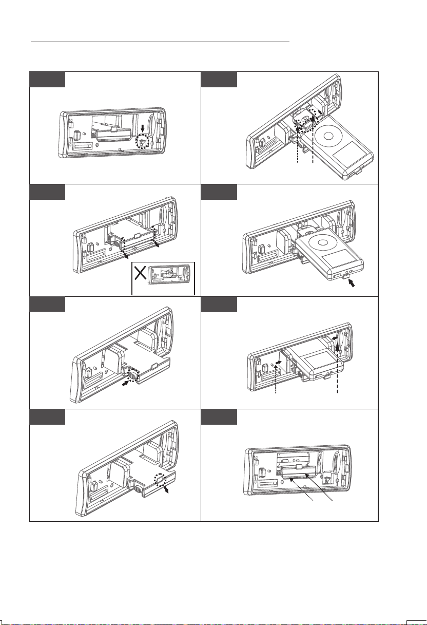
5. iPod OPERATION
INSTALLING iPod INTO THE BUILT-IN iPod DOCKING
Always follow the below steps to install the iPod into the docking station. Incorrect or improper
installation may cause permanent damage to the docking or the iPod unit.
Step 1
Press down the button as indicated
below to unlock the iPod docking.
Step 2
Pull out the iPod docking
as shown below.
Step 3
Press on these buttons
on both sides as
indicated below to unlock
the iPod holder.
Press down
Pull out
Never pull out this stick unless
docking is completely release out.
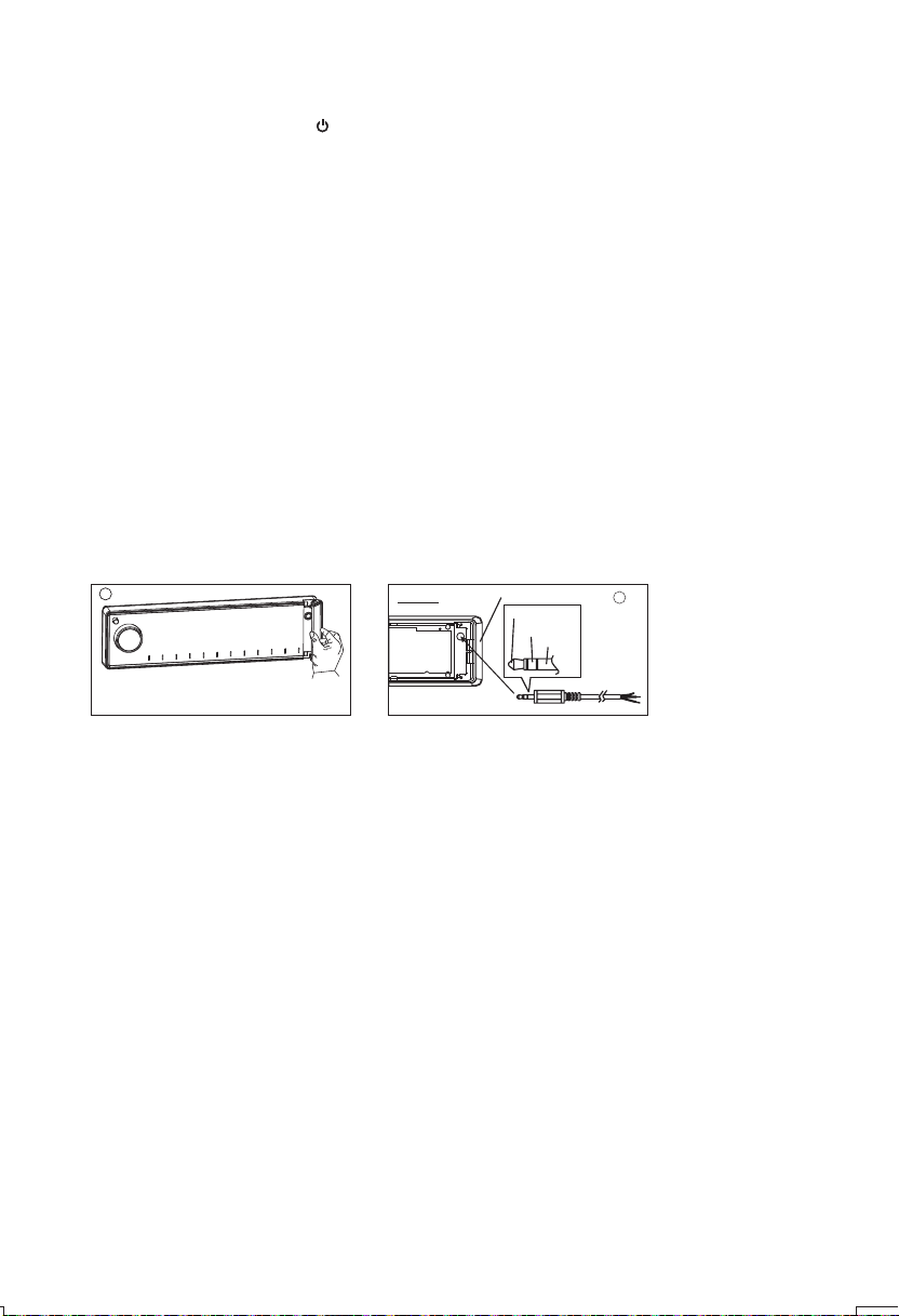
Step 5
Once the stick is
completely pulle d out,
user should see the
iPod connector,
and user can
connect
the iPod
to the
connector
as shown in this step.
Step 6
Push the stick & the connected iPod
inwards until it stops.
Step 7
Press the iPod holder on both sides
to hold the iPod firmly in place.
Press toward this
lock switch
Push inwards
Step 4
Press down this button
Pull out the iPod connector
as indicated below.
Pull out this stick
Step 8
7
P ress towards the iPod unit to hold the
i P od unit firmly in place
Push the iPod docking inwards into
the unit’s cabinent until a click sound
is heard.
Push the docking back
into the Cabinent
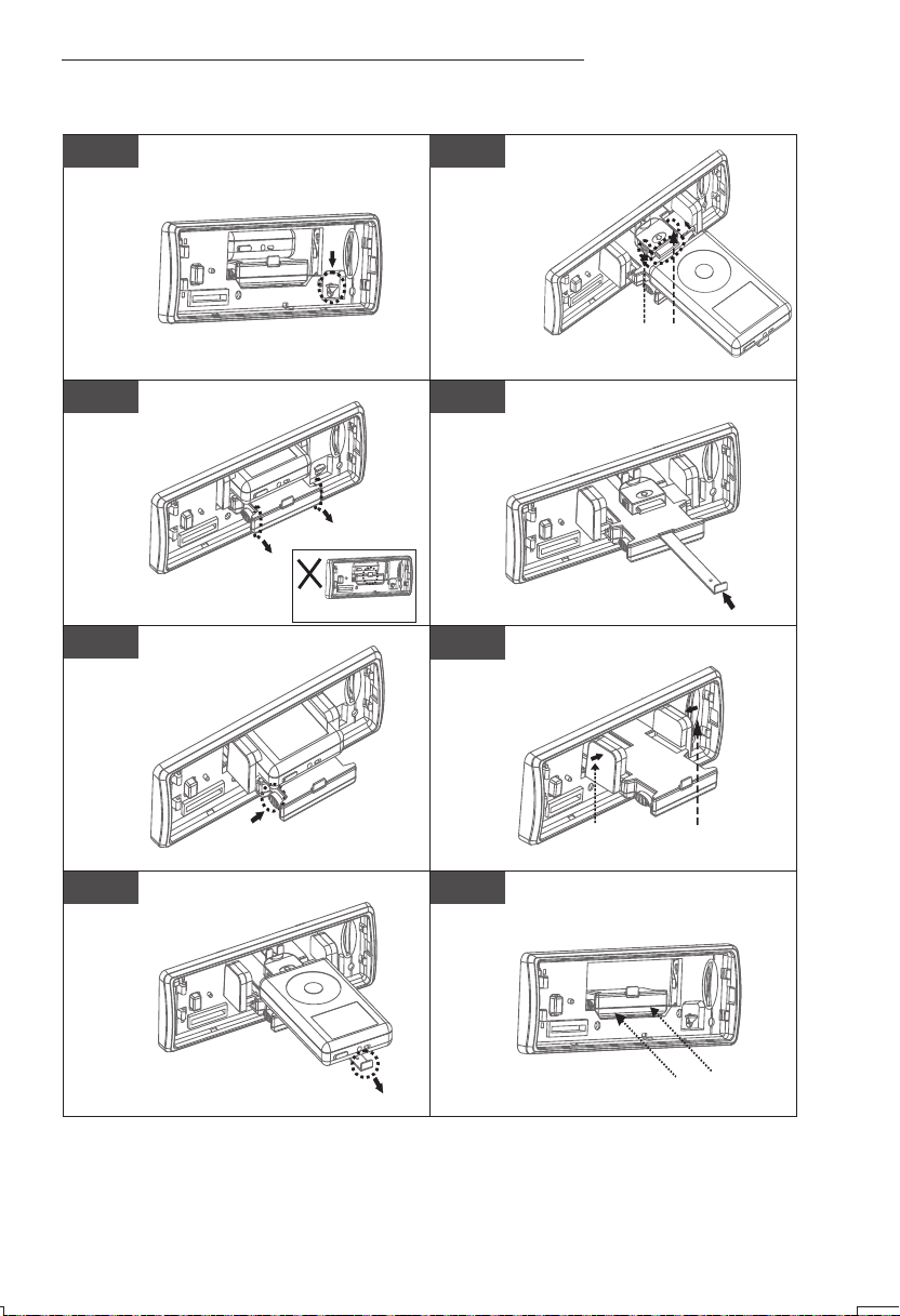
REMOVE iPod FROM THE BUILT-IN iPod DOCKING
To take out the iPod from the docking station, user can first detach the front panel, and repeat step
1 to step 8 to take out the iPod & return the iPod docking inside the unit’s cabinent.
Step 1
Press the button as indicated below
to unlock the iPod docking.
Press down
Step 5
connected iPod is completely
out, user should push on
the locking buttons
on the both sides
of the iPod
connector to
release the
iPod as
indicated in the
picture, and remove the iPod unit.
Step 2 Step 6
Pull out the iPod docking
as shown below.
into the iPod docking
station until it stops.
Pull out
Never pull out this stick unless
docking is release out.
Step 3
Press on these buttons
Step 7
on both sides as
indicated below to unlock
the iPod holder.
Once the stick with the
Press toward this
lock switch
Once the iPod unit is remove,
push the stick backward
Push inwards
Push on the iPod holders on both
sides until they stop.
Step 4
Pull out the iPod connected
as indicated below
by pulling out the stick.
Press down this button
Pull out this stick
Step 8
8
P ress towards the iPod unit to hold the
i P od unit firmly in place
Push the iPod docking inwards into
the unit’s cabinent until a click sound
is heard.
Push the docking back
to Cabinent
iPod F ULL CONTROL / OPERATION
This unit is equipped with iPod Ready function which allow end user to have direct control of the
iPod on the front panel control button and display iPod song information on the unit's LCD display.
Please read below for more details operation.
iPod Compatibility Chart
This unit is support following iPod version
iPod 1G Not Supported
iPod 2G Not Supported
iPod 3G Supported
iPod Mini Supported
iPod 4G Supported
iPod Photo Supported
iPod Nano Supported
iPod 5G(Video) Supported
iPod Touch Supported
iPhone Not Supported
iPod Classic All version
Audio Video File
This unit is NOT ABLE to playback any VIDEO FILE OR VIDEO ALBUM which contained in the iPod
Video.
Turning iPod Power On and Off
The iPod power turns on automatically as soon as it is connected to the 30 Pin Connector and as
long as the vehicle's ignition is turned ON. The iPod power can be turned OFF by removing the
iPod from the 30 Pin Connector or if the vehicle's ignition is turned OFF. Under this condition the
iPod will go into pause mode and goes into sleep mode about 2 minutes later.
While the iPod is connected, the power cannot be turned on or off from the iPod itself.
Tips
“ ” to disconnect will be shown in the iPod's display while it is connected to the unit .
OK to disconnect
iPod Battery Charging
While connected to the unit, the iPod will automatically start re-charging as long as the vehicle's
ignition key is turn to ACC or ON.
Switch to iPod Mode
When the Head unit is power on and iPod is connected to the 30 pin connector, press the mode
button to change to iPod mode and the unit will display for a while then starts
.
Press Mode button repeatedly to change to other modes or switch back to iPod mode.
iPod information Display on the Head Unit LCD
This unit can display the Song, Artist, Album name and Elapsed time on the LCD display, these
information can be displayed by pressing the AS/PS button repeatedly while a iPod Song file is
playing.
Searching a Desire Song
Under iPod playback mode, press BAND to enter into the iPod Searching Mode. Pressing BAND
button repeatedly to accesses the different searching methods as below :
the music files contained in the iPod and the playback will automatically start.
9

1) Playlist
2) Artist
3) Album
4) Song
5) Genre
Once selected the desire searching method, within 10 second press the AUDIO button as confirm
& access into the searching mode, then turn the rotate encode volume knob to navigate thru the
Album or Artist or Song contained in the iPod. Press the AUDIO button to confirm & play the
selected song. During the searching mode, press AS/PS as quick move back to the last upper
level of Album, Playlist, Genre, etc.
Song Select
Press the File UP (>>) or File DOWN (<<) button for less than one second to skip to the next or
previous song. Press and Hold File UP (>>) or File DOWN (<<) button for more than 3 seconds to
fast forward or fast reverse of the current song.
Song Repeat / Repeat All play :
Pressing the M3 button for more than 3 seconds during iPod playback mode for “REPEAT ALL”. All
songs of the current album will be kept on repeat playing until the “Repeat All” function is disabled.
To disable current Album “REPEAT ALL” function, long press M3 button more than 3 seconds.
Press the M3 button for less than 3 seconds to “REPEAT PLAY” the current song. And keep on
repeat playing the current song until the “REPEAT PLAY” function is disabled. To disable current
song “REPEAT PLAY”, press the M3 button less than 3 seconds.
Shuffle play: / Shuffle Album
Pressing the M4 button for more than 3 seconds during iPod playback mode to activate the
“SHUFFLE ALBUM” function. This function allows RANDOM playback of all the albums contained
on the iPod. To disable “SHUFFLE ALBUM” function, long press M4 button for more than 3
seconds.
Press the M4 button for less than 3 seconds during iPod playback mode to activate “SHUFFLE
PLAY”. This function allows the playback of all the songs in the iPod in random sequence. To
disable “SHUFFLE PLAY”, short press M4 button again for less than 3 seconds.
10
6. BASIC OPERATIONS
3) PANEL RELEASE BUTTON (REL)
Press this button to remove the control panel.
1) POWER ON/OFF BUTTON ( )
Press POWER button or any other button on the front of the radio to turn the unit on. Press
POWER button again to turn the unit off.
1) MUTE BUTTON (MUTE)
Press the mute button momentarily to mute the audio volume, and "Mute" will flash in the
display. Press the mute button again to restore volume to the previous setting.
8) SUBWOOFER (SUB)
Pressing the SUB button to activate the Subwoofer function On, and “Subwoofer” will appear
on the LCD display for 3 seconds. press the SUB button again to turn off the Subwoofer
function.
10) iX-BASS BUTTON (X-Bass )
Pressing the iX-Bass button to turn on the iX-Bass function, and “iX-Bass” will appear in the
LCD display for 3 seconds. Press the iX-Bass button again to turn off the iX-Bass function.
5) SOURCE BUTTON (SRC)
Press SRC button to select a different source of operation as indicated on the display panel.
Available modes include Tuner, USB Host, SD/MMC, iPod and Aux - In.
2) FRONT PANEL AUX-IN JACK
Connect the external signal to AUX in jack located at the front of the panel , then press SRC
button to select Aux mode. Press SRC Button again to cancel Aux Mode and return to
previous mode.
1
AUX IN
FRONT CABINET
LEFT TRACK
RIGHT TRACK
2
GROUND
OPEN THE AUX-IN JACK DOOR/COVER
TO ACCESS TO THE AUX-IN JACK
AUX IN
6) ENCODER VOLUME BUTTON
To increase the volume, rotate the volume control clockwise. To decrease the volume, rotate
the volume control counter clockwise. When volume is adjusted, the volume level will be
shown on the display panel as a number ranging from 0 (lowest) to 46 (highest).
11
7. MENU OPERATION
22) MENU FUNCTION LIST (SYS MENU)
Press SYS MENU to access the menu. will appear in the display momentarily.
Navigate the menu by pressing SYS MENU momentarily to move forward to the next option. The
menu can also be navigated by using the Tuning Up or Tuning Down Button to move to the next or
previous option. Once the desired option appears in the display, adjust that option by rotating the
volume control within 5 seconds. The following options are adjusted through this menu feature.
Download - Bluetooth Wireless Music File download
This feature can be used for wireless transfer of music file and store into this unit thru
Bluetooth wireless technology.
Tips
Please refer to the page “BLUETOOTH WIRELESS MUSIC FILE DOWNLOAD” for the
details operation of “DOWNLOAD”.
Paring
This feature is used to pairing the unit's Blue tooth system to your mobile phone or other Blue tooth
device. Under the MENU “Pairing” mode then press Audio button to start activating the Pairing.
Please refer to BLUE TOOTH HAND FREE Operation regarding the details operation of “PAIRING”.
Tips
Re-connection/Dis-connection
This feature is allows to Re-connect or Dis-connect to the paired mobile phone or Blue tooth
device by manually. Under the Menu- “RE-CONN”mode, Rotate the encoder to navigate thru
“RE-CONN” (re-connection) and “DIS-CONN”(Dis-connection). After selected the mode for
connection then press Audio button to start activating the connection mode.
Auto Answer (A ANSWER)
The unit is default of “off' mode. If “On” is selected. The unit is automatically answer any
incoming call without pressing PHONE button if ON is selected..
Contrast
The contrast level of the display is set at "CONTRAST 05" by default. Rotate the volume control
to adjust the contrast level from 00 to 10.
Clock Format
This option allows selection of a 12 hour or 24 hour clock format. "CLK FORMAT 12H" is the
Default setting. Rotate the volume control to change to the 24 hour clock format..
Time Set
The time on the clock will be set to 12:00 as the default. Program the current time by rotating
the volume control clockwise to adjust the minutes and counterclockwise to adjust the hours.
Local / Distance Select
This feature is used to designate the strength of the signals at which the radio will stop during
automatic tuning. "Distance" is the default, allowing the radio to stop at a broader range of
signals. To set the unit to select only strong local stations during automatic tuning, rotate the
volume control until "Local" appears in the display.
Beep Tone
The beep tone feature allows the selection of an audible beep tone to be heard each time a
button is pressed on the face of the radio. "BEEP TONE On" is the default display. Rotate the
volume control to select the "BEEP TONE Off" option.
AREA (TUNER FREQUENCY SPACING)
This option allows the selection of the frequency spacing appropriate for your area. " AREA
U.S.A. " is the default setting. Rotate the volume control to select the U.S.A. Latin America,
Europe or Oirt options.
IMPORTANT NOTE ON THE EUROPEAN / RDS TUNER SETTING
This unit is default at "U.S.A" frequency. When unit is in U.S.A frequency, all the RDS related
function is disabled. Once user change the AREA setting to "EUROPE", unit will change to
European frequency, and all the RDS function will be activated as well. So all the RDS related
function will only be activated, only if this unit's AREA setting is change to "EUROPE".
For details operaion of the RDS system, please refer to page “RDS Operation”.
12

8. AUDIO OPERATION
Audio Menu
Pressing “AUDIO button to access the Audio Menu. User can navigate thru the Audio Menu items
by pressing the “AUDIO” button repeatedly, or by pressing the Tuning Up or Tuning Down Button.
Once the desired menu item appears on the display, adjust that option by using the Volume Up or
Down button within 5 seconds. The following menu items can be adjusted as described above.
The unit will automatically exit the Audio Menu after five seconds of inactivity.
VOLUME (Volume Level)
User has 5 seconds to use the Volume button to adjust the desire volume level, the volume
level will be shown on the LCD display ranging from 00 (lowest) to 46 (highest).
BASS (Bass Level)
User has 5 seconds to use the Volume Up or Down button to adjust the desired Bass level
range from -6 to +6.
TREBLE (Treble Level)
User has 5 seconds to use the Volume Up or Down button to adjust the desired Treble level
range from -6 to +6.
BALANCE
User has 5 seconds to use the Volume Up or Down button to adjust the Balance between the
right and left speakers from R12 (full right) to L12 (full left). “C00” represents an equal balance
between the right and left speakers.
FADER
User has 5 seconds to use Volume Up or Down button to adjust the Fader between the front
and rear speakers from R12 (full rear) to F12 (full front). “C00” represents an equal balance
between the front and rear speakers.
”
13

9. TUNER OPERATION
7) BAND BUTTON (BAND)
Press BAND to change between FM bands and AM(MW)bands.
20-21) TUNING UP/DOWN BUTTON ( )
Manual Tuning
Press the Up Tuning or Down Tuning button for more than 3 seconds to move the radio
frequency number up or down one step.
Auto Seek Tuning
Press the Up Tuning or Down Tuning button for less than 3 seconds to move to next station
automatically.
12-17) PRESET STATIONS BUTTONS
Six numbered preset buttons store and recall stations for each band.
Store a Station
Select a band (if needed), then select a station. Hold a preset button for 3 seconds. The
preset number will appear in the display.
Recall a Station
Select a band (if needed). Press a preset button to select the corresponding stored
station.
11) AUTOMATICALLY STORE / PRESET SCAN (AS/PS)
Automatically Store
Automatically select 6 strong stations and store them in the current band. Select a band (if
needed). Press AS/PS button for more than three seconds. The new stations replace
stations already stored in that band.
Preset Scan
Scan stations stored in the current band. Select a band (if needed). Press AS/PS button for
less than 3 seconds. The unit will pause for ten seconds at each preset station. Press
AS/PS button again to stop scanning when the desired station is reached.
STEREO
The unit will automatically pick up a stereo signal, when available. When in stereo mode,
the ST icon appears in the display. When no stereo signal is available, the unit will
automatically revert to mono operation, and no icon will be displayed.
14
 Loading...