

Boss Audio 738BI User Manual


CONTENTS LIST
PAGE CONTENTS
2 NOTEOFDISCS
3 ACCESSORY INCLUDED
4 INSTALLATION
6 DETACHABLE CONTROL PANEL
7 WIRING DIAGRAM
8 CONTROL PANEL FUNCTION
9 BASIC OPERATIONS
10 MENU OPERATION
11 AUDIO OPERATION
12 TUNER OPERATION
13 CD /MP3/WMA OPERATION
16 USB OPERATION
17 MEMORY CARD OPERATION
18 MUSIC FILES COPYING / TRANSFERRING
20 MUSIC FILES TRANSFERRING
22 FILES MANAGER
23 iPod OPERATION
25 BLUETOOTH HAND FREE OPERATION
37 REMOTE FUNCTION
38 SPECIFICATIONS
39 TROUBLE SHOOTING
1
1. NOTE OF DISCS
MOISTURE CONDENSATION
On a rainy day or in a very damp area, moisture may condense on the lenses inside the unit.
Should this occur, the unit will not operate properly. In such a case, remove the disc and wait for
about an hour until the moisture has evaporated.
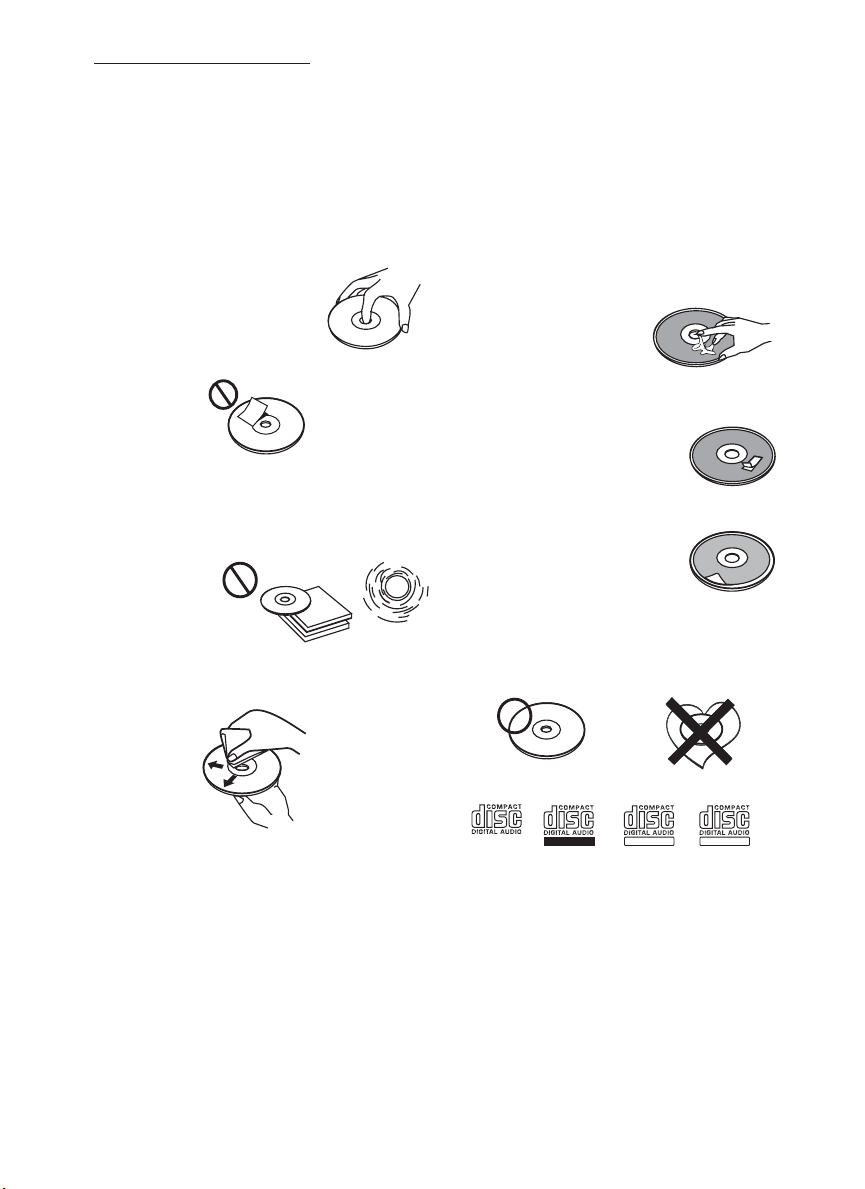
NOTES ON CDs
1.
A dirty or defective disc may cause sound
dropouts while playing. To enjoy optimum
sound, handle the disc as follows.
Handle the disc by its edge. To keep the
disc clean, do not touch the surface (P.1).
2.
Do not stick paper or tape on the disc (P.2).
P. 2
Do not expose the discs to direct sunlight or
3.
heat sources such as hot air-ducts, or leave
them in a car parked in direct sunlight where
there can be a considerable rise in
temperature inside the car (P.3).
P. 3
4.
Before playing, clean the discs with an
optional cleaning cloth. Wipe each disc from
the centre out (P.4).
P. 1
NOTES ON DISCS
If you use the discs explained below, the
sticky residue can cause the CD to stop
spinning andmay cause malfunction or ruin
your discs.
Do not use second-hand or rental CDs that
have a sticky residue on the surface (for
example, from peeled-off stickers or from
ink, or glue leaking from under the stickers).
There are paste residue.
Ink is sticky (P.5).
P. 5
Do not use rental CDs with old labels that
are beginning to peel off.
Stickers that are beginning
to peel away, leaving a
sticky residue (P.6).
P. 6
Do not use your CDs with labels or stickers
attached.
Labels are attached (P.7).
Do Not Use Special Shape CDs
P. 7
Be sure to use round shape CDs only for
this unit and do not use any special shape
CDs. Use of special shape CDs may cause
the unit to malfunction.(P.8).
****
*******
*******
*******
*******
**************
*******
*******
*******
*******
*******
*******
*******
*******
P. 4
5.
Do not use solvents such as benzine,
thinner,commercially available cleaners, or
antistatic spray intended for analog discs.
Be sure to use CDs with disc mark
P. 8
RECORDABLE
REWRITABLE
Only for this unit.
CD-Rs and CD-RWs which have not
undergone finalization processing cannot
be played. (For more information on
finalization processing, refer to the manual
for your CD-R/CD-RW writing software or
CD-R/CD-RW recorder.) Additionally,
depending on the recording status, it may
prove impossible to play certain CDs
record on CD-R or CD-RW.
2
TEXT
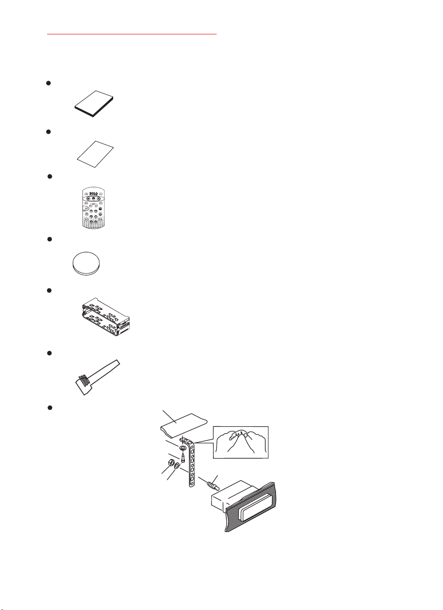
2. ACCESSORY INCLUDED
When first unpacking your new full detachable DVD head unit, please check first that the package
contains all of the items below. If something is missing, contact the store where you purchased
the player.
Owner’s Manual
Owner’s
manual
Warranty Card
Warranty
Card
Remote control
Lithium Battery
+
Lithium Cell
CR2025
3V
SC5
Half Sheeve
Insert Key
1. Dashboard
2. Nut (5mm)
3. Spring washer
4. Screw (4X12mm)
5. Screw
6. Support Strap
7. Plain washer
1
6
7
4
2
5
3
3
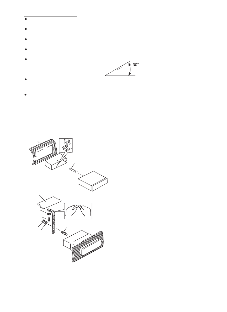
3. INSTALLATION
Before finally installing the unit, connect the wiring temporarily and make sure it is all
connected up properly and the unit and system work properly.
Use only the parts included with the unit to ensure proper installation. The use of
unauthorized parts can cause malfunctions.
Consult with your nearest dealer if installation requires the drilling of holes or other
modifications of the vehicle.
Install the unit where it does not get in the driver's way and cannot injure the passenger if
there is a sudden stop, like an emergency stop.
If installation angle exceeds 30° from horizontal, the unit might not give its optimum
performance.
Avoid installing the unit where it would be subject to high temperature, such as from direct
sunlight, or from hot air, from heater, or where it would be subject to dust dirt or excessive
vibration.
Be sure to remove the front panel before installing the unit.
DIN FRONT/REAR-MOUNT
This unit can be property installed either from “Front” (conventional DIN Front-mount)or“Rear”
(DIN Rear-mount installation, utilizing threaded screw holes at the sides of the unit chassis).
For details, refer to the following illustrated installation methods A and B.
DIN FRONT-MOUNT (Method A)
Installation the unit
1
182
53
2
3
1
6
7
4
2
5
3
1. Dashboard
2. Holder
After inserting the half sleeve into the
dashboard, select the appropriate tab
according to the thickness of the
dashboard material and bend them
inwards to secure the holder in place.
3. Screw
1. Dashboard
2. Nut (5mm)
3. Spring washer
4. Screw (4x12mm)
5. Screw
6. Support Strap
Be sure to use the support strap to secure
the back of the unit in place. The strap can
be bent by hand to the desired angle.
7. Plain washer
4
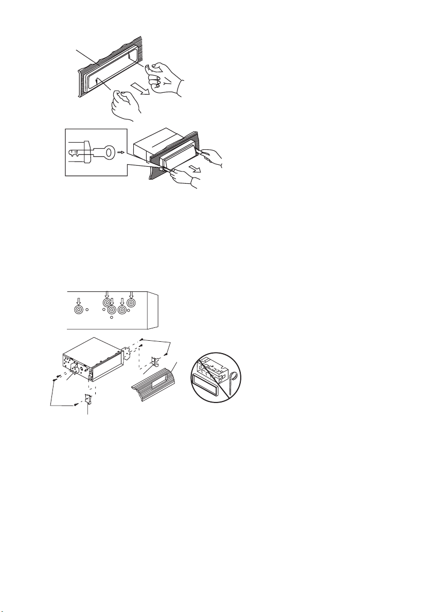
Removing the unit
a
a. Frame
b. Insert fingers into the groove in the
front of frame and pull out to remove
the frame. (When re-attaching the
b
c
Trim Plate Installation:
Push the trim plate against the chassis until it is fitted.
You must do this before you install the front panel, otherwise it can't be attached.
DIN REAR-MOUNT (METHOD B)
Installation using the screw holes on the sides of the unit.
Fastening the unit to the factory radio mounting bracket.
2
4
5
3
2
5
frame, point the side with a groove
down wards and attach it.)
c. Insert the levers supplied with the
unit into the grooves at both sides of
the unit as shown in figure until they
click. Pulling the levers makes it
possible to remove the unit from the
dashboard.
1. Select a position where the screw
holes of the bracket and the screw
holes of the main unit become
aligned (are fitted) and tighten the
screws at 2 places on each side.
2. Screw
3. Factoryradiomountingbracket.
4. Dashboard or Console
5. Hook (Remove this part)
Note: the mounting box, outer trim ring,
and half-sleeve are not used for method
B installation.
5
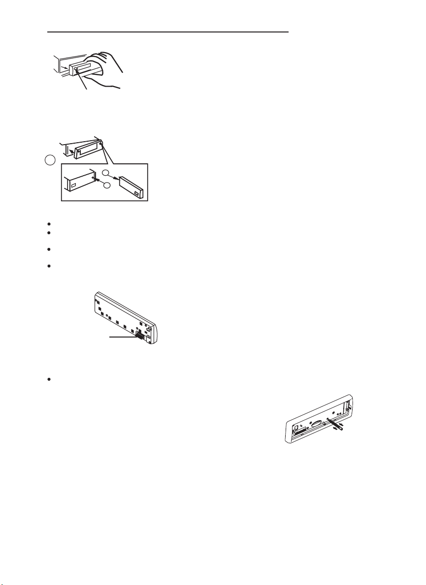
4. DETACHABLE CONTROL PANEL (D.C.P.)
Removing The Detachable Control Panel (D.C.P.).
1. Turn the power off
2. Press the D.C.P. release button
PANEL RELEASE
BUTTON
Attaching the DCP
3. Remove the D.C.P.
2
A
B
1. Attach the panel at the right side first, with
point B on the main unit touching point A on the
D.C.P. (Asshownonthediagram).
2. Then press the left side of D.C.P. ontothemain
unit until a “click” sound is heard.
CAUTION
DO NOT inserttheD.C.P fromtheleft side. Doingsomaydamage it.
The D.C.Pcaneasily be damagedbyshocks. After removing it,placeit in aprotectivecase and be carefulnot
to drop itorsubject it to strongshocks.
When the release button is pressed and the D.C.P is unlocked, the car's vibrations may cause it to fall. To
prevent damage totheD.C.P, always storeitin a protectivecaseafter detaching it.
The rear connector thatconnectsthe main unit andtheD.C.P is anextremelyimportant part. Be careful notto
damage it bypressingon it with fingernails,pens,screwdrivers, etc.
Note:
If the D.C.P is dirty, wipe off the dirt with soft, dry
cloth only. And use a cotton swab soaked in
isopropyl alcohol to clean the socket on the
Socket
back of the D.C.P.
RESETTING THE UNIT:
After releasing the front panel, use a pencil or any non-metalic object to press & hold the reset
button for five seconds to reset the unit.
RESET
6
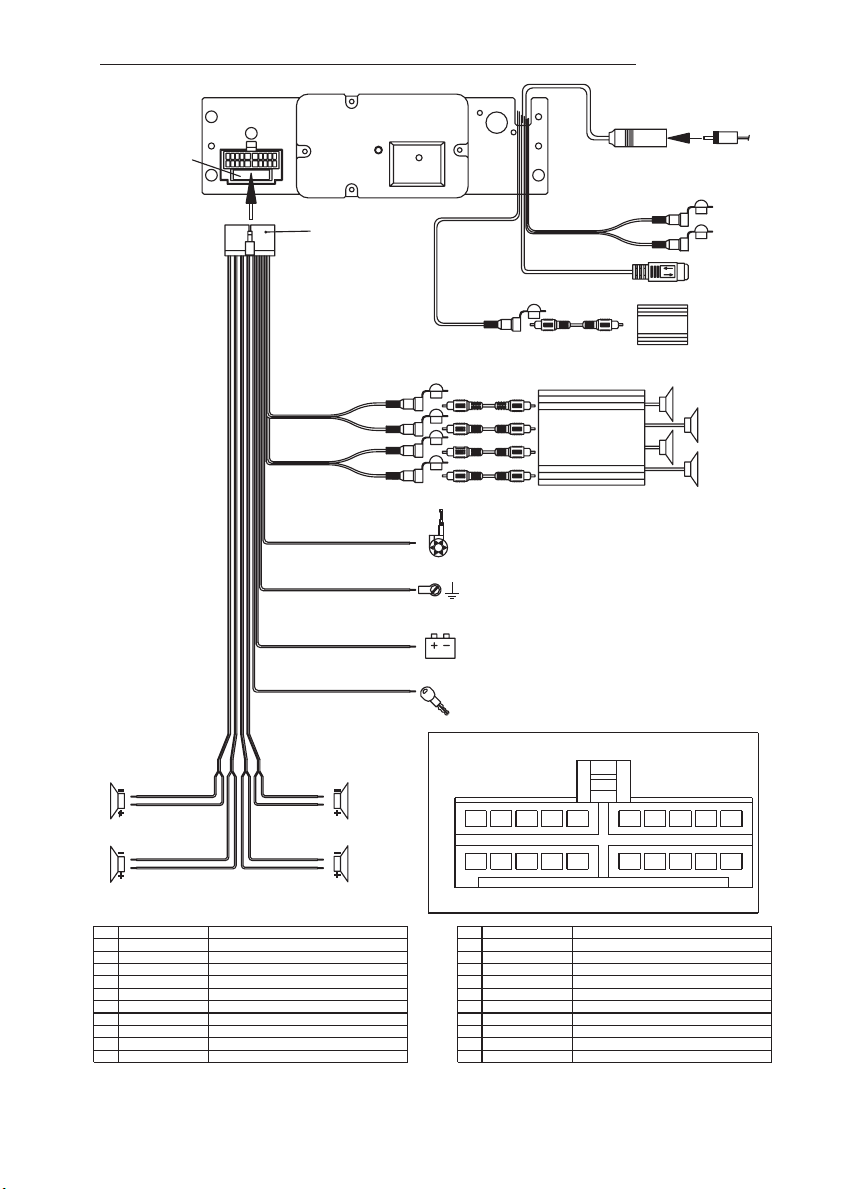
5. WIRING DIAGRAM (20 PIN HARNESS PLUG)
FUSE
20-PIN
AUDIO/POWER
HARNESS
(See Figure 1)
GREY
REAR LINE OUT
BLACK
FRONT LINE OUT
BLACK
YELL
BLUE
RED
WHITE
RED
WHITE
RED
OW
BLUE
YELLOW
iPod ready cable(IPC40)
RCA-TO-RCA CABLES
WHITE
SUB WOOFER
RCA-TO-RCA CABLES
(not supplied)
L-CH
R-CH
L-CH
R-CH
Power antenna wire that can also be used
for remote turn on lead.
Ground Connect to ground terminal or
Clean unpainted metal part of
Memory/Battery
Connect to a constant 12 volt source.
The radio will not work if this wire is not connected.
Accessory/Ignition Connect to existing radio wire or radio fuse.
WHITE
(not supplied)
AMP
chassis
ANTENNA
JACK
SUB-WOOFER
RED
WHITE
ANTENNA
CABLE INPUT
R-CH
L-CH
iPod
AUX LINE IN
LEFT FRONT
WHITE-BLACK LF-
WHITE LF+
LEFT REAR
GREEN-BLACK LR -
GREEN LR+
WIRE COLOR
PIN
1 GREY/BLACK
2 GREY
3 VIOLET
4 VIOLET/BLACK
5
6 GREEN
7 GREEN/BLACK
8 RED
9 BLACK
10 RED
RIGHT FRONT
GREY-BLACK RF-
GREY RF+
RIGHT REAR
VIOLET-BLACK RR-
VIOLET RR+
FUNCTION/LABEL
RIGHT FRONT SPEAKER (-)
RIGHT FRONT SPEAKER (+)
RIGHT REAR SPEAKER (+)
RIGHT REAR SPEAKER (-)
LEFT REAR SPEAKER (+)
LEFT REAR SPEAKER (-)
IGNITION(ACC)
REAR PRE-AMP LINE OUT COMMON
RIGHT REAR PRE-AMP LINE OUT
20-PIN AUDIO/POWER HARNESS
653412
79810
PIN
11
12
13
14
15
16
17
18
19
20
Figure 1
WIRE COLOR
WHITE
WHITE/BLACK
BLUE
YELLOW
BLACK
WHITE
RED
BLACK
WHITE
141311 12 15 16
FUNCTION/LABEL
LEFT FRONT SPEAKER (+)
LEFT FRONT SPEAKER (-)
POWER ANTENNA
BATTERY(+)
CHASSIS GROUND
LEFT FRONT PRE-AMP LINE OUT
RIGHT FRONT PRE-AMP LINE OUT
FRONT PRE-AMP LINE OUT COMMON
LEFT REAR PRE-AMP LINE OUT
201817 19
Pin View
7
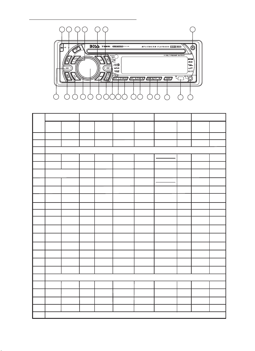
6. CONTROL PANEL FUNCTION
21
OPERATIONS:
KEY
2
3
4
5
6
7
8
9
10
11
12
13
14
15
16
17
18
19
20
21
22
23
24
SYSTEM TUNER
Short
Press
Power
1
Source
Encoder Volume
Sub-W
Copy
ix-Bass
Display
Mute
Menu
1
3
22
23
11 13
Long
Press
Audio
Menu
Short
Press
Band
PS
M1
M2
M3
M4
M5
M6
Seek Up
Seek
Down
456
8
18
Memory 1
Memory 2
Memory 3
Memory 4
Memory 5
Memory 6
Tune Up
9
207
12
CD/MP3/WMA
Long
Press
Tune
Down
Short
Press
Eject
Panel release button
Enter
File/Folder
Search
AS
ID3
Pause
/Play
Intro
Repeat
Random
Folder
Down
Folder
Up
USB Socket
Track/File
Up
Track/File
Down
AUX-IN JACK
14
15
16 17
Long
Press
File
Erase
Folder
Intro
Folder
Repeat
Folder
Random
Fast
Forward
Fast
Backward
10
Blue Tooth
Short
Press
Phone
Answer
Reject Call
End Call
19
Long
Press
Call
Transfer
2
24
Search
information
File Up
File Down
Short
Press
iPod
iPod
Pause
/Play
Repeat
Shuffle
iPod
Long
Press
Album
Repeat
Album
Shuffle
Fast
Forward
Fast
Backward
8
7. BASIC OPERATIONS
3) PANEL RELEASE BUTTON (REL)
Press this button to remove thecontrolpanel.
1) POWER ON/OFF BUTTON ( )
Press POWER button or any other button on the front of the radio to turn the unit on. Press
POWER button again to turn the unit off.
22) MUTE BUTTON (MUTE)
Press the mute button momentarily to mute the audio volume, and "Mute" will flash in the
display.Pressthemutebuttonagaintorestorevolumetotheprevioussetting.
8) SUB-WOOFER (SUB-W)
Short press the SUB-W button to activate the Sub-woofer function On, and “Sub-woofer” will
appear on the LCD display for 3 seconds. press the SUB-W button again to turn off the Subwoofer function.
10) iX-BASS BUTTON (iX-Bass )
Short press the iX-Bass button to turn on the IX-Bassfunction, and the “X-BAS” icon will appear
on the LCD display.PresstheiX-Bass buttonagaintoturnofftheIX-Bass function.
5) SOURCE BUTTON (SOURCE)
Press SOURCE button to select a different mode of operation as indicated on the display
panel. Available modes include Tuner, CDP, USB Host, SD/MMC ,iPod, Built-in memory and
Aux Line In .
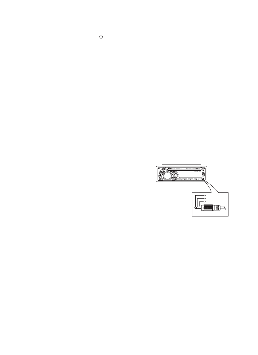
19) FRONT (AND REAR PANEL) AUXILIARY INPUT JACKS
This unit features AUX IN line input jacks on both the front (headphone type) and rear (RCA
type) panels.
PLEASE NOTE:
These two inputs cannot be used simultaneously. If
you have a source unit plugged into the rear panel
jack and wish to listen to a portable device (such as
an MP3 player) by using the front panel jack, be sure
to power off the unit plugged into the rear unit to
avoid interference.
Similarly, if you have a device plugged into the front
panel jack and wish to listen to the unit plugged into
the rear panel, be sure to turn off the front panel
device.
To select either the front or rear AUX INdevice as a listening source, press the SOURCE button
to select AUX mode. To cancel AUXINlistening,pressSOURCEagain.
AUX IN JACK IN PANEL
3.5mmAudio In Cable(not included)
1
Left Audio
2
RightAudio
3
Ground
6) ENCODER VOLUME BUTTON
To increase the volume, rotate the volume control clockwise.To decrease the volume, rotate
the volume control counter clockwise. When volume is adjusted, the volume level will be
shown on the display panel as a number ranging from 0 (lowest) to 46 (highest).
9
8. MENU OPERATION
23) MENU FUNCTION LIST (MENU)
Press MENU for morethan 3 seconds to access the menu. Will appearin the display
momentarily. Navigate the menu by pressing MENU momentarily to move forward to the next
option. The menu can also be navigated by using the Tuning Up or Tuning Down Button to
move to the nextorprevious option. Once the desired option appears inthedisplay, adjust that
option by rotating the volume control within 5 seconds. The following options are adjusted
through this menu feature.
Pairing ( PAIRHF)
This feature is used to pairing the unit's Blue tooth system to your mobile phone or other Blue
tooth device. Under the MENU “Pairing” mode then press Audio button to start activating the
Pairing.
“PAIR HF” is special use for pairing with mobile phone with Bluetooth function, if the
pairing device is a Bluetooth Audio device, rotate the encoder to “PAIR AD” then
press Audio button to start activating the pairing with audio device.
Tips
Pls refer to BLUE TOOTH HAND FREE Operation regarding the details operation of
“PAIRING”.
Re-connection/Dis-connection (RE-CON / DIS-CON )
This feature is allows to Re-connect or Dis-connect to the paired mobile phone or Blue tooth
device by manually. Under the Menu- “RE-CON”mode, Rotate the encoder to navigate thru
“RE-CON” (re-connection) and “DIS-CON”(Dis-connection). After selected the mode for
connection then press Audio button to start activating the connection mode.
Incoming call ringing volume ( VOL)
The unit can preset the Ringing volume level for any incoming call. The default RINGING
VOLUME LEVEL VALUEis“20”.RotatetheencoderknobtoadjustfromMin00toMax38.
Time Set ( CLK )
The time on the clock will be set to 12:00 as the default. Program the current time by rotating
the volume control clockwise to adjust the minutes and counterclockwise to adjust the hours.
AREA (TUNER FREQUENCY SPACING)
This option allows the selection of the frequency spacing appropriate for your area. "AREA
U.S.A." is the default setting. Rotate the volume control to select the U.S.A. Latin America,
Europe or Oirt options.
Local / Distance Select
This feature is used to designate the strength of the signals at which the radio will stop during
automatic tuning. "Distance" is the default, allowing the radio to stop at a broader range of
signals. To set the unit to select only strong local stations during automatic tuning, rotate the
volume control until "Local" appears in the display.
Programmable Turn-onVolume ( P-VOL )
This option allows selection of the volume level the radio will automatically assume when first
turned on. "VOL PGM 12 " is the default setting, which will turn the radioon at the volume level
selected when the unit was last turned off.
To program a specific volume level fortheradioto turn on at, rotate the volume controltoselect
"VOLUME LEVEL”. Within 5 seconds
Beep Tone ( BEEP )
The beep tone feature allows the selection of an audible beep tone to be heard each time a
button is pressed on the face of the radio. "BEEP TONE On" is the default display. Rotate the
volume control to select the "BEEP TONE Off" option.
BT
10

9. AUDIO OPERATION
Audio Menu
Long Press “AUDIO button to access the Audio Menu. User can navigate thru the Audio Menu
items by pressing the / “AUDIO” button repeatedly, or by pressing the Tuning Up or Tuning Down
Button. Once the desired menu item appears on the display, adjust that option by using the
Volume Up or Down button within 5 seconds. The following menu items can be adjusted as
described above. The unit will automatically exit the Audio Menu after five seconds of inactivity.
VOLUME (Volume Level)
User has 5 seconds to use the Volume button to adjust the desire volume level, the volume
level will be shown on the LCD display ranging from 00 (lowest) to 46 (highest).
BASS (Bass Level)
User has 5 seconds to use the Volume Up or Down button to adjust the desired Bass level
range from -6 to +6.
TREBLE (Treble Level)
User has 5 seconds to use the Volume Up or Down button to adjust the desired Treble level
range from -6 to +6.
BALANCE
User has 5 seconds to use the Volume Up or Down button to adjust the Balance between
the right and left speakers from R12 (full right) to L12 (full left). “C00” represents an equal
balance between the right and left speakers.
FADER
User has 5 seconds to use Volume Up or Down button to adjust the Fader between the
front and rear speakers from R12 (full rear) to F12 (full front). “C00” represents an equal
balance between the front and rear speakers.
”
11

10. TUNER OPERATION
7) BAND BUTTON (BAND/SEARCH)
Press BAND to change between FM bands and AM(MW)bands.
20-21) TUNING UP/DOWN BUTTON ( )
Manual Tuning
Press the Up Tuning or Down Tuning button for more than 3 seconds to move the radio
frequency number up or down one step.
Auto Seek Tuning
Press the Up Tuning or Down Tuning button for less than 3 seconds to move to next station
automatically.
12-17) PRESET STATIONS BUTTONS
Six numbered preset buttons store and recall stations for each band.
Store a Station
Select a band (if needed), then select a station. Hold a preset button for 3 seconds. The
preset number will appear in the display.
Recall a Station
Select a band (if needed). Press a preset button toselectthecorrespondingstoredstation.
11) AUTOMATICALLY STORE / PRESET SCAN (AS/PS)
Automatically Store
Automatically select 6 strong stations and store them in the current band. Select a band (if
needed). Press AS/PS button for more than three seconds. The new stations replace
stations already stored in that band.
Preset Scan
Scan stations stored in the current band. Selecta band (if needed). Press AS/PS button for
less than 3 seconds. The unitwillpausefortensecondsat each preset station. Press AS/PS
button again to stop scanning when the desired station is reached.
STEREO
The unit will automatically pick up a stereo signal, when available. When in stereo mode,
the ST icon appears in the display. When no stereo signal is available, the unit will
automatically revert to mono operation, and no icon will be displayed.
12
 Loading...